Close
0%
0%

Open MPPT

Open Source MPPT for Solar charging.

Similar projects worth following
This is designed as a fairly easy to build, high-performance MPPT using off the shelf components. While this means slightly increased cost due to not using microcontrollers, it reduces the complexing for building this device without knowledge of programming, or when you want it to "Just Work".

This is designed to be a companion to the Open BMS, to form the beginnings of a completely open source off-grid power solution for Medium-Small installations.

The design is based on the TI BQ24650 IC and designed to be as generic as possible.
The unit uses the common XT30 style input jacks, as these are capable of high currents while keeping the total unit cost down.

The size of the PCB is selected to allow the unit to be installed in the cheap extruded aluminium cases available online.

The first design of the unit has been tested and works with the small bodge mounted diode. Further testing and refinement is in progress.

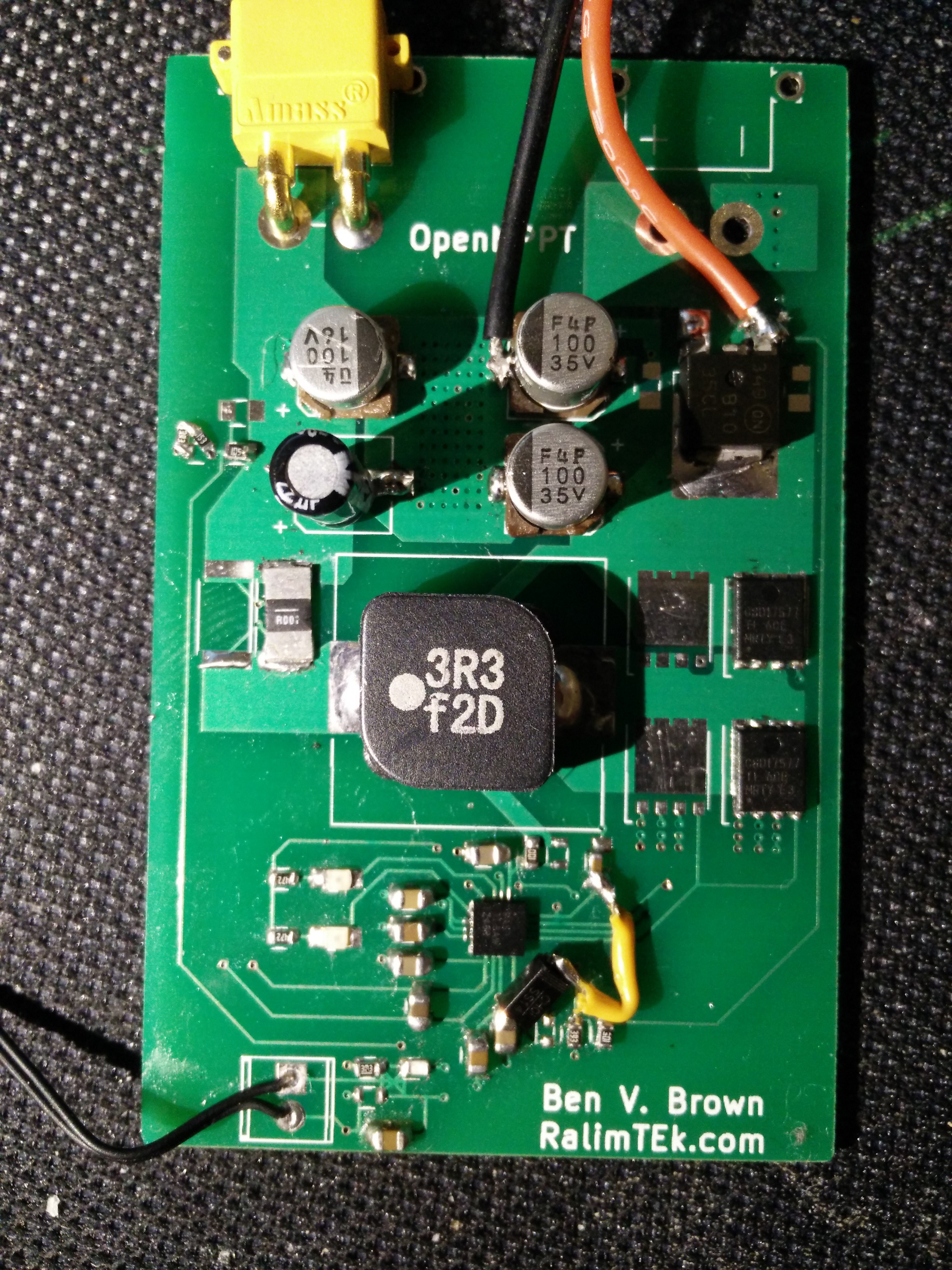
The MPPT design is based on the IC by TI, this is mostly to serve as either a nice generic unit for people to use, or as an open source reference design.

I'm no expert is designing these things, however I feel like the design is OK :)

The design is made to fit into one of the common aluminium enclosures available from China. These are often sold as 80x50x20 enclosures.

By using the XT30PW style connectors, we can allow for around 20A continuous current, and use an extremely common connector that is available worldwide.

  • 1 × BQ24650 Evaluation, Demonstration Kits, Boards and Modules / Evaluation Kits, Boards and Modules
  • 4 × AON7400B N-ch MOSFET
  • 1 × SRR1210-3R3YCT-ND Inductor
  • 1 × XT30PW Hobby 20A connectors
  • 1 × 80x50x20mm Aluminium Enclosure Metal case for the unit

  • Efficiency

    Ben Brown07/28/2017 at 09:44 0 comments

    After having been testing the initial unit's performance for the past few days on and off, I have found a few notes to efficiency.

    Using 19V input to provide 3S(12.3V)@4A output, the unit achieves extremely good ~95% efficiency of power out/power in. my bench power supply measures 51.3W output, and 12.25V@4A output.

    Testing at 16V, 19V and 21V provides similar figures +-0.5% so this looks excellent for the design.

    However, it appears that almost all of the 2W of heat is coming out in the QFN for some reason, which causes it to heat up rather quickly. Sometimes tripping the internal over temperature lockout.

    I'm currently investigating this, and looking into easier solutions to reduce the thermal loss in the QFN.

    If the thermal losses in the QFN cannot be reduced, I may need to investigate heat sinking to the outside case.

  • Bad PCB Design (my error)

    Ben Brown07/25/2017 at 03:01 0 comments

    After building up the first PCB for testing the design, I have found an error in my design in that my switching loop is too large. I sort-of expected this but wanted to test the design to find out for sure. For the testing PCB, I have tacked on extra filtering capacitors as well which has helped slightly as I initially completely mind-blanked on installing ceramic filter capacitors.

    I will be revising the design of the PCB to amend these issues soon.

    That all said, the unit does work well at 4A output current, regulates well, and charges the battery quite nicely. But just runs hotter than expected. I will be testing efficiency in the coming days when I have more time to sit down with the unit.

  • PCB's Back & functioning unit!

    Ben Brown07/21/2017 at 13:44 0 comments

    PCBs!

    I received the PCB's back from SeeedStudio this morning and naturally had to build up one to test the design.

    As I was populating the board I realised my main mistake on the design, which was to use a completely too tiny diode package, which is why there is a large wire across the PCB.

    I'm also completely out of the XT30PW connectors I need to populate the board, having only been able to find one so far. So I have run a wire for the input side for the mean time.

    The boards turned out perfectly otherwise, which is very nice to see after waiting for them to arrive.

    Testing

    The unit was setup for an MPPT voltage of approximately 18V and output voltage of 12.3V. 

    This allows the use of a standard 3S lipo with the common 19V laptop power supplies, as well as most solar panels.

    On the first power up the unit did not work straight away (wouldn't it be nice if it just worked).

    The Schottky diode used for the bootstrap circuit needs to be a decent model, and the first one I used had too low of a breakdown voltage (I think) which allows the voltage at the REGN pin to go up to around 9V. This resulted in the main IC getting very hot quickly.

    Once this was replaced with the larger diode (seen above), the main IC was still drawing a large amount of power, so it was replaced with the spare main IC. 

    After replacing the main IC the unit powered up much more stable and now appears to work... Mostly.

    Running the unit at 2.5A input (4A output), the main IC runs cool and stable, and the switching MOSFETs are staying nice and cool as well. However the input filter caps that I used are not rated for the pulse current the unit is drawing, and get hot after only a few minutes of runtime.  I plan to replace these with better-rated capacitors and then test the unit for a longer period of time.

  • Initial design concepts sent off to fab

    Ben Brown07/11/2017 at 12:26 0 comments

    The first revision of the design has been sent off to Seeed to have manufactured.

    Hopefully my layout is okay for this first revision, but If not that just makes it fun to figure out why :)

    I have most of the components on hand already, so mostly just waiting for the PCB's to arrive, probably 2-3 weeks away though.

  • Initial design finished

    Ben Brown07/08/2017 at 09:18 2 comments

    The initial design for the pcb is finished, and will be sent off to fabrication once I have more designs to panelize the design with.

    As far as I know the design is complete, so anyone should be able to order one and test it out if you're really eager :)

View all 5 project logs

Enjoy this project?

Share

Discussions

Similar Projects

Does this project spark your interest?

Become a member to follow this project and never miss any updates