The teoretical fundaments of my project
These can also be found in my medium posts.
Layers of creation in music
The last couple of decades have been plentiful of new tools in the area of music creation, and the knowledge of electronic music making is mostly about music making technologies knowledge. Albeit obvious, I find this idea pretty important, because unlike previously being human hearing, harmony and acoustics knowledge, the factor of music technology is determined deliberate actions. Behind every technology there is a person and an intention (regardless of whether this intention was accomplished or not by the technology). So now, the sequencer knows how to play, and you don’t have to perform by yourself a TB-303 bass-line, but in order to do this, you must purchase the piece (not different from traditional instruments) and you must know how to use this technology. This brought the -once innocent- consequence that the performer now was designed by an industrial counterpart, and not by the composer. The brick maker becomes more influential than the architect when it comes to architectural design.
Many different decisions in the electronic music instrument making, have heavily shaped the path of music making, so much that the earliest groove-boxes and rhythms machines, pretty much dictated the creations of new styles, whose characteristics were based on the instrument’s architecture and sound. If the most direct rhythm structure to make in a drum machine is 4/4, divided in 16 steps, suddenly the whole resolution of electronic music becomes 4/4, 16 steps. It didn’t matter that there was a way of making patterns in 3/4 signature. This has been great fun, because there has been some sort of ecosystem where designers and engineers create a stage where musicians and creators experiment, and have some musical outcomes. If the designers provide a low cut knob to the synth, electronic music then starts expressing through that knob.
Current state on electronic music performance instruments
It has been 34 years since the TB 303 and I believe that the electronic music instruments is much less naive than it used to be. Each of the musical instrument makers offer their own universe of possibilities, and have an interaction statement. For instance, Ableton aims to a very computer based, performance, and pretty much tries to blur the limits between production and performance when they produce hardware that turns a DAW into a performance instrument (Push). Reaper is trying to do this as well with the Nektar Panorama. Native instruments is searching for a very dj based performance: they come from the dj culture with Traktor, and Maschine tries to decompose music making into single tracks and samples. The Dj’ing software Traktor is trying to go towards merging with live production by introducing the stems concept (to separate music tracks into separate stems, so the DJ’s can get more creative with these) and introducing some looping features that are completely new to the idea of DJ’ing. In the other side, Maschine, achieves a very good groove-box by presenting a controller for their own Maschine DAW, that has very limited possibilities, and presenting in a hardware piece, the most common music making parameters. Limiting possibilities is not a bad strategy for a performance instrument, as I will explain later. Pioneer has now launched their own version of a live electronic music performance instrument; the Toraiz, that intends to mix the two worlds of groovebox and DJ’ing. I personally think that the Toraiz needs a bit of maturing, but will be a great tool in a bunch of software updates later. Korg also has been long ago creating groove-boxes, aiming more for a more analogue feel: the EMX 1’s even have a little window that let a couple of tube amplifiers exposed to the view. Korg has it’s own synth culture, and the newest Electribe versions EMX 2 and ESX 2, manage to keep some of this inheritance albeit they are purely digital machines:...
Read more »


 Xasin
Xasin
 brtnst
 c.Invent
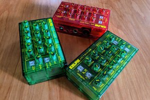
 Kenneth Marut