Close
0%
0%

SMidi - Soft MIDI Pedals

Full function, class compliant MIDI pedals you can roll up.

Similar projects worth following
Goals:
Soft construction for easier transport.
Durable, reliable, spill resistant, cheap to build.
No pcb or external electronics required.
Note, velocity, and aftertouch capable.

My current MIDI pedals are wearing out, so I'm building some new ones.

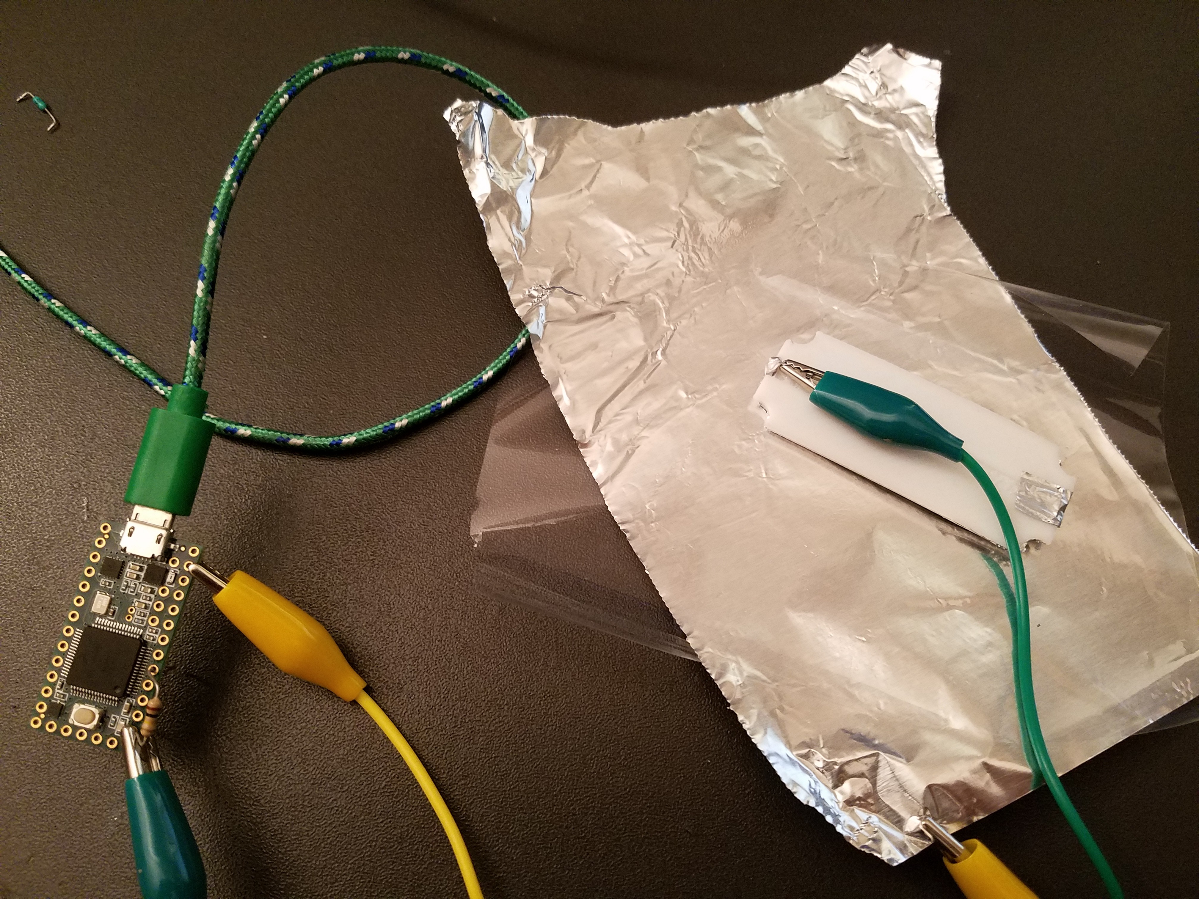
Goal is to be able to directly wire to the Teensy and require no external electronics.

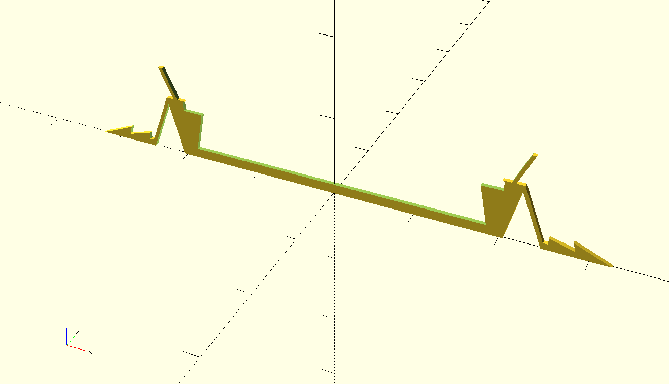
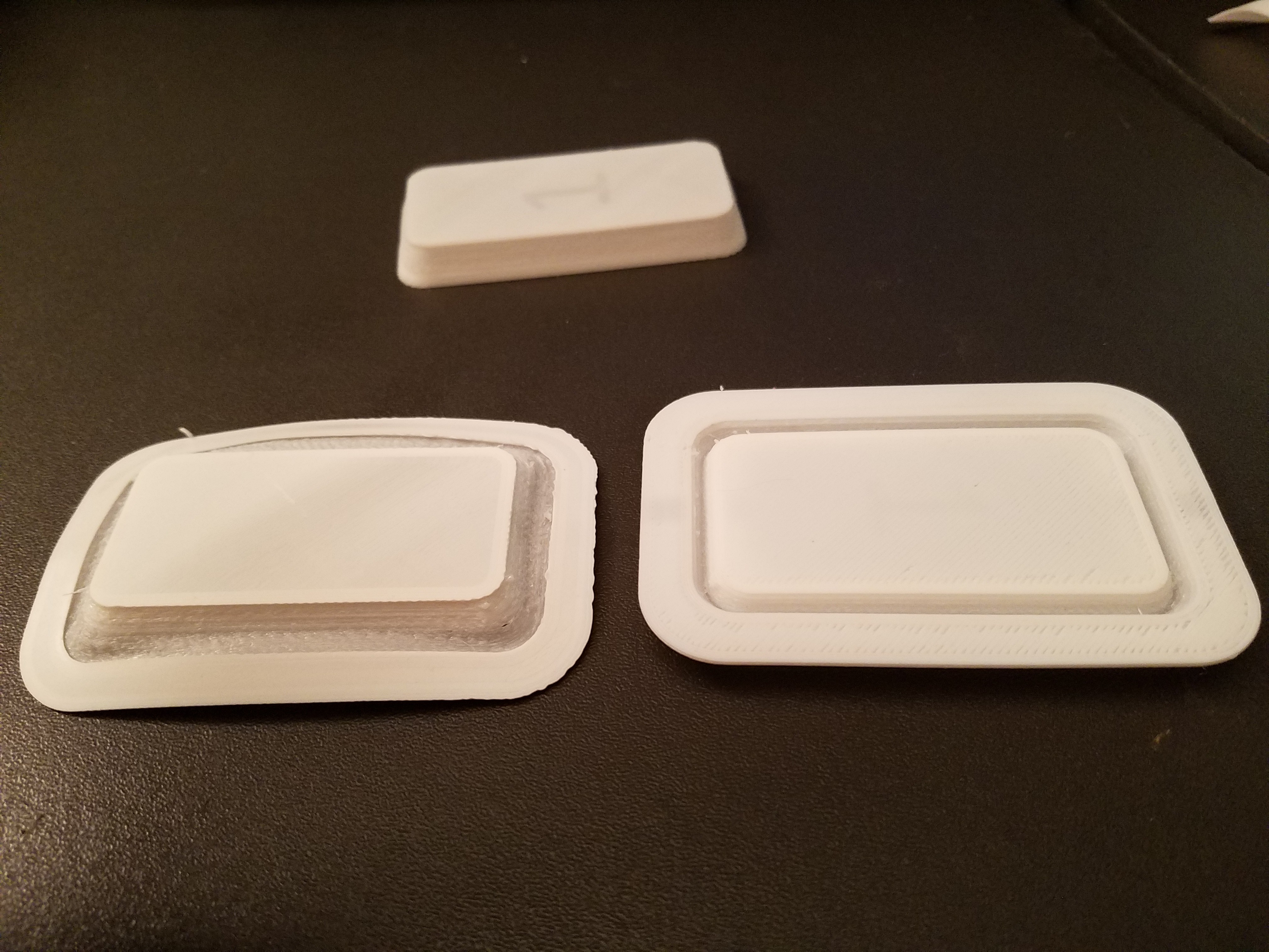
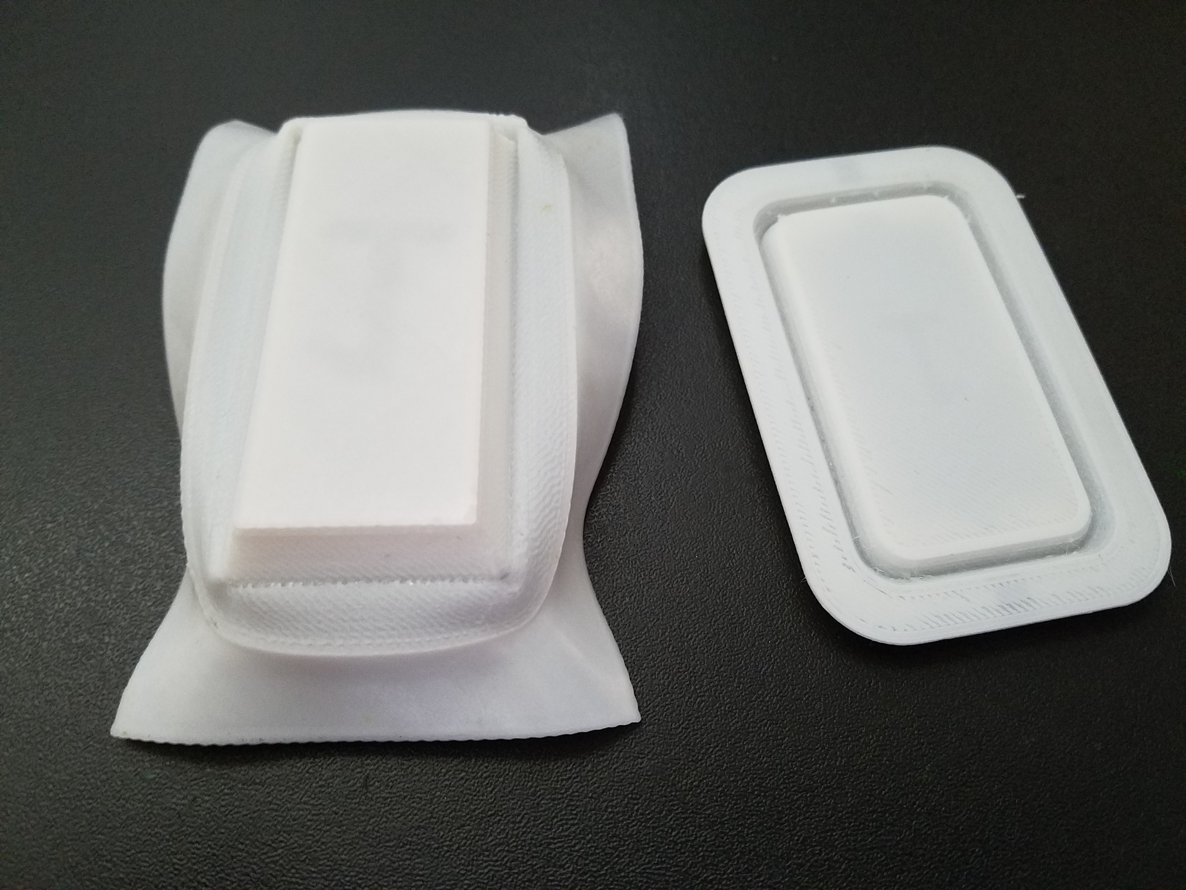
Design has migrated from using home made FSR resistors to a novel 3D printed pressure sensitive capacitor.

Current code works for 16 channels with lots of headroom to spare.

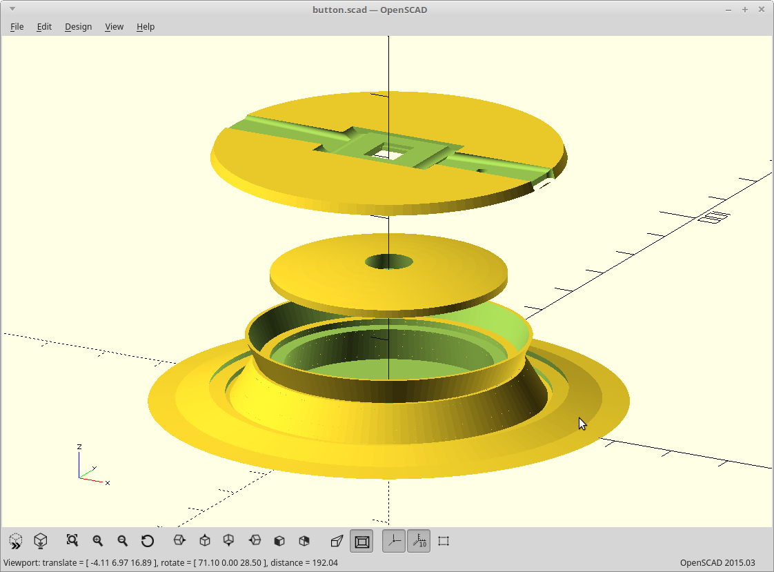
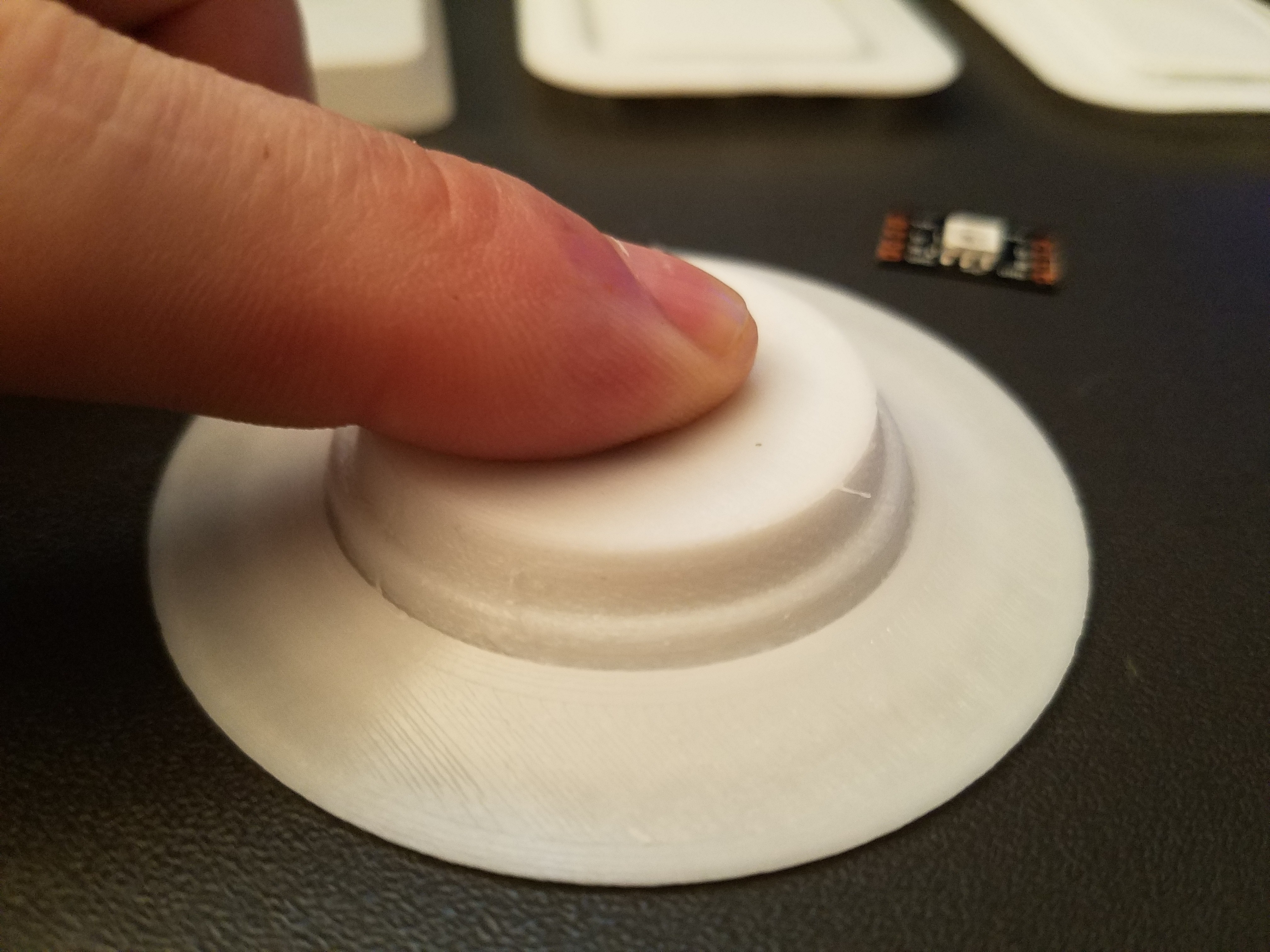
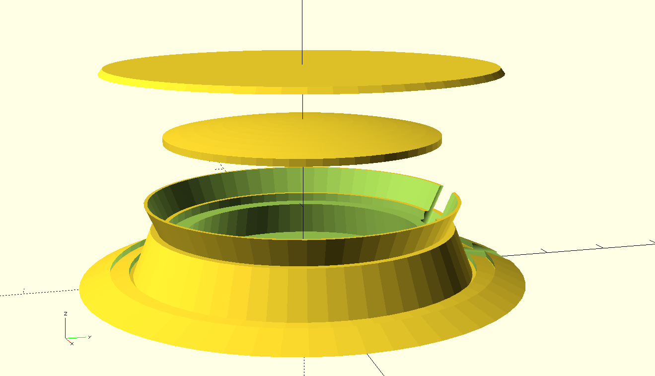
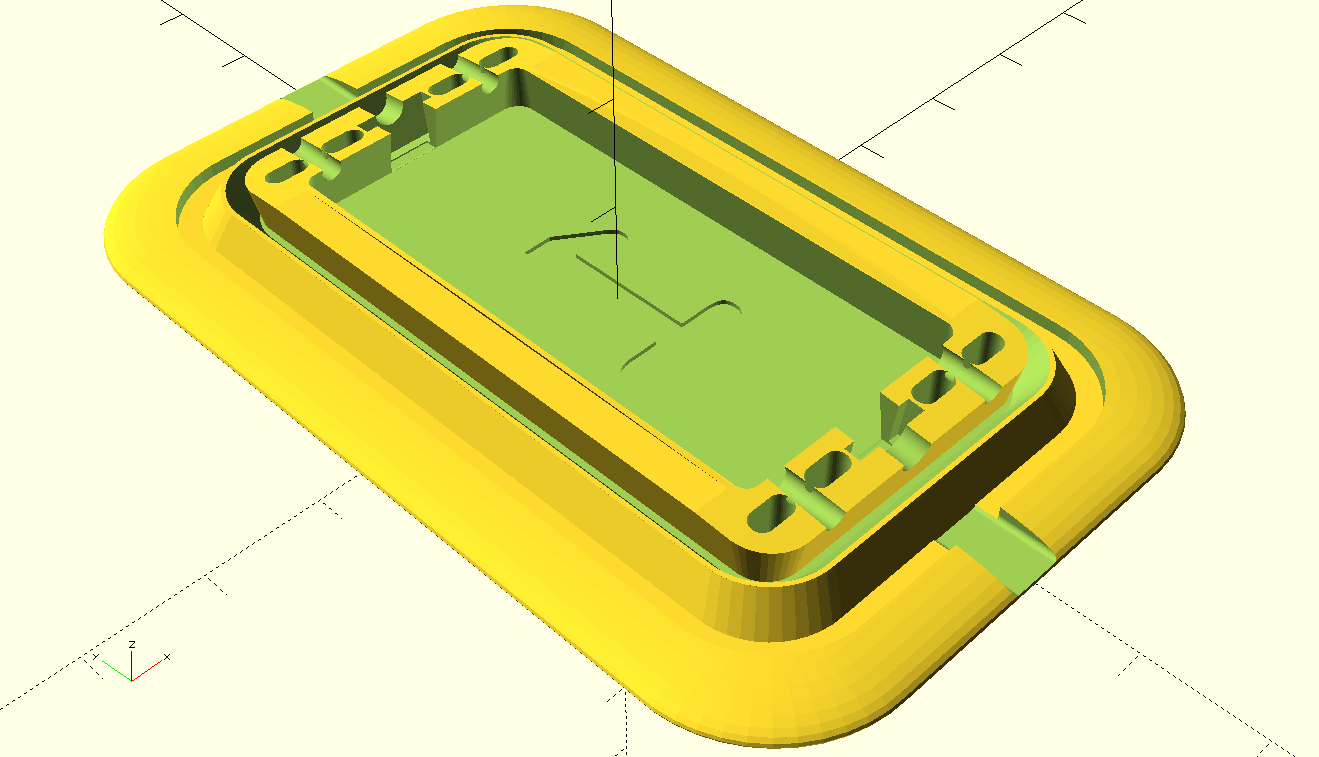
Current work is on designing the physical foot pad for no supports printing and blinken-lightyness.

  • Ooops... where are the hardware files?

    Daren Schwenke03/25/2019 at 21:11 0 comments

    I just realized.  Apparently I never uploaded the hardware source files for this.  Wow, how time flies.  

    I do remember 7 failed branches of ideas working towards a print-flat, pop through, TPU button, and finally one 'good one'.  

    I'll get at least the good one uploaded when I sort out what is what.

    <EDIT>

    Found the latest OpenSCAD source, updated the Readme.md and files with license information, and pushed it up to Github.

    This version added a cutout for a Dotstar module to shine through from the bottom.  This eliminated wiring within the button itself.  Also, placing the module inside the button made for a rather unattractive point light source, whereas putting it below gives it a larger distance to spread out.  

    There may have been polyester fiber-fill involved as a diffuser, but I can't remember which worked better.  Experiment!!

    In any case, the dome shape and disc get covered in AL foil with spray glue, and a sheet of non-aluminized mylar (gift wrapping plastic) placed between them for use as a dielectric.  

    This formed the capacitor that the Teensy could read.  Pressure applied to it would deform the dome and increase the capacitance.  It was still more of a log() curve than linear response and perhaps some scaling is in order.

    </EDIT>

  • Over-sprung

    Daren Schwenke06/30/2017 at 23:01 0 comments

    Finished printing.

    Angle of pop through was too vertical now.

    Conical spring was too tall now.

    Base lip was too small to take the force and stretched.

    I'm thinking I'm going to make individual buttons and sew/bond them to some fabric backed vinyl instead of printing a sheet of them. Printing a sheet would consume a lot of TPU for not a lot of gain. Also means I can decide on a layout later.

    Adjusted. Printing again..

    Edit: Pop was still too vertical and conical spring was too low now. Printing again..

  • Popped

    Daren Schwenke06/30/2017 at 19:41 0 comments

    Going circular worked.

    Button pops through after printing and stays there when pressed due to a 'spring' I added internally.

    Sensor pad position was too low, so modeled a new one which fixes that, adds the grooves for the bottom cover to mount, and adds wire paths.

    Cross section of the latest. The fish hook profile on the edges is where the base cover will attach to seal it. The bits extending above now form a conical spring which helps keep the hinge inverted and will allow me to tune the force required to push the button without altering the sensor pad itself. The lip on the inner edge is where the sensor pad rests, and is allowed to flex as it's only supported on the edges.

    Exploded view.

    It is printing.

  • Pop is ok, but has issues

    Daren Schwenke06/30/2017 at 03:50 2 comments

    I tried one more time. Over-extruded at the start as I didn't calibrate, but I was just interested in testing the pop-through mainly, so I just let it finish.

    So... the one on the left has a steeper angle on my accordion fold. Basically as far as I can push the overhang in TPU without supports, about a 45 degree angle.

    It's also mixed material, with the first .5mm being 50/50 ABS/TPU, so not something your average user could produce anyway.

    This stiffened it up enough to maintain it's shape and allow the accordion to work, but the steep overhang angle makes it look terrible. I refuse to give in to supports!

    I wish I could get this sorted. If this worked, I could print the entire top as a single, water-resistant unit (or two, but just limited by printable area).

    Edit: Looking closely at my success and failure here, I noticed that the corners work well while the straight sections.. don't. So I'm starting over in OpenSCAD and making one that is all corners... aka... round. :)

  • Pop sucks

    Daren Schwenke06/29/2017 at 17:54 0 comments

    The pop button worked worse than the last one. The TPU is not flexible enough at the minimum thickness I can print.

    Cura currently turns walls thinner than 0.41 into thin air for me.

    The one on the left is the previous attempt with square corners. That was a mistake as when it's inverted the corners are a shorter path so it distorts.

    The one on the right has rounded corners, but won't stay inverted as the TPU is not flexible enough at 0.4mm thickness.

    If this is going to be spill resistant, it has to have a one part design for the top or be glued together which adds a whole other set of problems.

    I think I may experiment with making molds and using real silicone.

  • Pop music?

    Daren Schwenke06/29/2017 at 00:05 0 comments

    Had another go at a pop-through button design.

    So you print it flat, and upside down, then flip it over and pop it through so it stands up.

    This gives a nice finish on both the button and the lip, and makes it one piece.

    Or so goes the theory.

    Changed it to an all-flexible, 3 part design with no supports required for printing.

    Moved the Dotstar modules to the ends. I have an idea for diffusing the light. We'll see if it pops correctly first. The last one I tried I believe the corner radius was too small so it didn't work right.

  • Multiplexing fail

    Daren Schwenke06/27/2017 at 18:48 0 comments

    Well, multiplexing by moving the ground around was a fail.

    The idea was to use two to four digital pins and change which was tied to ground and which was floating.

    So tie a pin to ground, measure all analogs, tie a different pin to ground, measure all analogs.

    Basically two rows of sensors, and which digital pin was tied low would determine which row I was reading.

    Moving the ground around didn't work. At all.

    Flipping the polarity of the entire setup so I was setting the digital pins HIGH and then using INPUT_PULLDOWN worked, but then I lost 2/3 of my range. This may seem backwards, but remember I'm reading the charge accumulation so my reference is to the rail it's starting from.

    I'm thinking this is due to the internal structure of the digital pins. Perhaps a small cap would give me the coupling I need, but then switching them would be a lot slower too.

    For now I'm dropping back to 16 inputs. Maybe 20 if I can mount the 4 resistors I would need directly to the Teensy. I could use the other 16 digital inputs too, but I won't be getting to the 24 analog inputs I needed to do a full 12 key keyboard with 2 axis of control per key simply. Drat.

  • Smooth operator

    Daren Schwenke06/27/2017 at 01:21 0 comments

    Put the capacitive reading code to use.

    Started with code from here: https://forum.pjrc.com/threads/31797-Teensy-FSR-based-MIDI-controller

    Added a calibration stage where it detects the base capacitance at startup.

    Modified it to use this library for smoothing the input: https://github.com/dxinteractive/ResponsiveAnalogRead

    Toyed with the charging timing and other variables, and I now have this:

    #include <ResponsiveAnalogRead.h>
    
    const int pinCount = 16;
    const int velocityThreshold = 65;
    const int afterThreshold = 75;
    const int velocityTime = 55;
    const int afterTime = 200;
    const int defaultMax = 450;
    const float chargeTime = 2; //rise time for external capacitors in us.
    
    ResponsiveAnalogRead pinReader[pinCount] = {
      ResponsiveAnalogRead(A0,true),
      ResponsiveAnalogRead(A1,true),
      ResponsiveAnalogRead(A2,true),
      ResponsiveAnalogRead(A3,true),
      ResponsiveAnalogRead(A4,true),
      ResponsiveAnalogRead(A5,true),
      ResponsiveAnalogRead(A6,true),
      ResponsiveAnalogRead(A7,true),
      ResponsiveAnalogRead(A8,true),
      ResponsiveAnalogRead(A9,true),
      ResponsiveAnalogRead(A15,true),
      ResponsiveAnalogRead(A16,true),
      ResponsiveAnalogRead(A17,true),
      ResponsiveAnalogRead(A18,true),
      ResponsiveAnalogRead(A19,true),
      ResponsiveAnalogRead(A20,true)
    };
    int pin[] = {A0,A1,A2,A3,A4,A5,A6,A7,A8,A9,A15,A16,A17,A18,A19,A20};
    int note[] = {60,61,62,63,64,65,66,67,68,69,70,71,72,73,74,75,76};       //MIDI notes
    const int midiMin = 10;
    
    int pinMin[pinCount];
    int pinMax[pinCount];
    int pinTimer[pinCount];
    int velocityMask[pinCount];
    
    
    void setup() {
      //Serial.begin (32500);
      Serial.begin (115200);
      analogReadResolution(10);
      //analogReadAveraging(4);
      // Set baseline capacitance for offset.  Read 20, average, set.
      for (int c = 0; c < 20; c++ ) {
        for (int i = 0; i < pinCount; i++) {
          pinMode(pin[i],INPUT_PULLUP);
          delayMicroseconds(chargeTime);
          pinReader[i].update();
          pinMode(pin[i],OUTPUT);
          digitalWrite(pin[i],LOW);
        }
      }
      for (int i = 0; i < pinCount; i++) {
          pinMin[i] = pinReader[i].getValue();
          pinMax[i] = defaultMax;
          Serial.print("Offset: ");
          Serial.print(i);
          Serial.print(" : ");
          Serial.println(pinMin[i]);
      }
      delay(5);
    }
    
    void loop () {
      for (int i = 0; i < pinCount; i++) {
        pinMode(pin[i],INPUT_PULLUP);
        delayMicroseconds(chargeTime);
        pinReader[i].update();
        int value = pinMin[i] - pinReader[i].getValue();
        pinMode(pin[i],OUTPUT);
        digitalWrite(pin[i],LOW);
        if (value > velocityThreshold) {
          pinTimer[i] ++;
          if ( value > pinMax[i] ) {
            pinMax[i] = value;
          }
          if (!(velocityMask[i] & (1 << i)) && (pinTimer[i] == velocityTime)) {
            velocityMask[i] |= (1 << i);
            pinTimer [i] = 0;
            int velocity = map (value, 0, pinMax[i], midiMin, 127);
            usbMIDI.sendNoteOn (note[i], velocity, 1);
            Serial.print("NoteOn: ");
            Serial.print(note[i]);
            Serial.print(" : ");
            Serial.println(velocity);
          }
          if (pinTimer [i] == afterTime) {
            pinTimer [i] = 0;
            if (value > afterThreshold) {
              int aftertouch = map (value, 0, pinMax[i], midiMin, 127);
              usbMIDI.sendPolyPressure (note[i], aftertouch, 1);
              Serial.print("PolyPressure: ");
              Serial.print(note[i]);
              Serial.print(" : ");
              Serial.println(aftertouch);
            }
          }
        }
        else {
          if (velocityMask[i] & (1 << i)) {
            velocityMask[i] &= ~ (1 << i);
            usbMIDI.sendNoteOff (note[i], 0, 1);
            Serial.print("NoteOff: ");
            Serial.print(note[i]);
            Serial.print(" : ");
            Serial.println("0");
            pinTimer [i] = 0;
          }
        }
      }
    }

    Which gives me this on a long press of my test sensor.

    NoteOn: 60 : 90
    PolyPressure: 60 : 88
    PolyPressure: 60 : 92
    PolyPressure: 60 : 95
    PolyPressure: 60 : 98
    PolyPressure: 60 : 102
    PolyPressure: 60 : 108
    PolyPressure: 60 : 113
    PolyPressure: 60 : 113
    PolyPressure: 60 : 102
    PolyPressure: 60 : 92
    PolyPressure: 60 : 88
    PolyPressure: 60 : 88
    NoteOff: 60 : 0
    
    Reading 16 inputs, it's still quite snappy and I have quite a bit of cycles to spare.

    Now to see if I can multiplex my 16 inputs into 64 with no external hardware. :)

  • Back to zero

    Daren Schwenke06/26/2017 at 15:28 0 comments

    Removed the external 100k resistor and tried using the internal pullup resistor again.

    Works.

    void setup() {
      Serial.begin (115200);
      analogReadResolution(16);
    }
    void loop () {   
      pinMode(A0,INPUT_PULLUP);
      delay(0.4);    
      int c = analogRead(A0);
      Serial.print(c);
      Serial.print("\n");
      pinMode(A0,OUTPUT);
      digitalWrite(A0,LOW);
      delay(20);
    }

    A single press captured in all it's glory

    60424
    59284
    59347
    56480
    52928
    52245
    50397
    45113
    41819
    38814
    35965
    33451
    31761
    31011
    30624
    29825
    29207
    29131
    

    So I can go back to zero external components required, probably.

  • Capacitive force sensors?!

    Daren Schwenke06/26/2017 at 05:42 0 comments

    I was thinking that's a pretty big bit of AL foil there, I wonder what it's capacitance would be (relatively speaking).

    I still have no idea as my meter sucks, but I was able to measure it changing with the Teensy.

    Code:

    void setup() {
      Serial.begin (115200);
      pinMode(A4,OUTPUT);
      pinMode(A0,INPUT);
      analogReadResolution(12);
    }
    void loop () {   
      digitalWrite(A4,HIGH); // Charge external capacitance
      delay(2);
      digitalWrite(A4,LOW); // Discharge through resistor.
      delay(0.1);    // Delay   
      int c = analogRead(A0); //Measure change.
      Serial.print(c);
      Serial.print("\n");
      delay(100);
    }

    Yeah, I'm using the analog alias of A4 instead of 'pin 18' for digital stuff... shoot me.

    How it's working:

    The Teensy toggles A4 between high/low states. There is a 100k resistor tied between A0 and A4. A0 is connected to my test pad, with the other foil connected to digital ground. This forms a simple RC network where R is constant and C is my two bits of aluminum foil separated by mylar. Reading the change in charging speed allows me to know C, which corresponds to how close the two bits of foil are to each other.

    I'm obviously not compressing the mylar very much. The reason I think it's working so well is one of my contact surfaces is curved and the pressure flattens it out. The bottom of my original FSR test contact pad was a row of cylinders. As my pad is made from sparse infill TPU, it can compress which brings the valley areas of the foil closer.

    My ultra precise test rig:

    I'm getting about 2% deviation with a static load, and better than a 50% of full scale swing under pressure. That's a lot better performance than when I was using it as a resistor.

    I'll take it. I think I'll be exploring this direction now.

    There is also the possibility of multiplexing the inputs too by changing my charging source dynamically.

    I'll need to experiment with the pad shape and see if I can get a linear response out of this.

View all 14 project logs

Enjoy this project?

Share

Discussions

Similar Projects

Does this project spark your interest?

Become a member to follow this project and never miss any updates