Close
0%
0%

MappyDot

Micro Smart LiDAR Sensor

Similar projects worth following
MappyDot is a smart ranging sensor which provides system designers with the ability to measure accurate distances on drones and robotic platforms for collision avoidance, area mapping, distance measurement, gesture recognition and motion sensing. The MappyDot uses the VL53L0X/VL53L1X laser time-of-flight ranging sensor from STMicroelectronics, which is a tried and tested 940nm Class 1 laser sensor in use in millions of devices worldwide.

The MappyDot can be used for example to prevent your drone from colliding with objects or optimise its landing, make star trek like door sensors to open doors automatically, create vibration sensors for the blind or even fashion unique musical instruments.

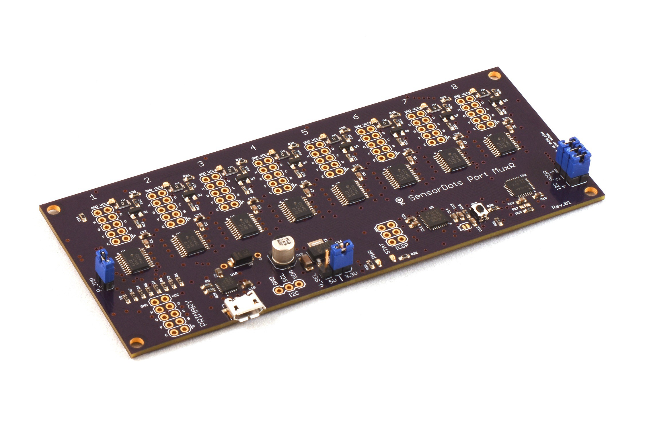
The MappyDot is part of a planned suite of enhanced sensor breakouts that offer additional measurement filtering, an easy to use I2C interface, crosstalk reduction and an automatic bus addressing scheme. This helps you integrate the sensor easily compared to its standalone counterpart, which require a complicated bus multiplexing setup, large processing overheads, a code and memory heavy API and a difficult to use I2C interface.

MappyDots provide distance measurements up to 2 meters at a non-interpolated rate up to 50Hz (or 4 meters and 100Hz for the Plus model), with a 25 degree field of view (adjustable on the Plus model). Multiple MappyDots can be chained together easily to gather multi-dimentional data about an area much like radar, without reducing sampling rate due to processing overheads. They are also calibrated out-of-the-box to within ±1mm, and can be easily re-calibrated if integrated into a commercial enclosure. The MappyDot also performs low pass filtering on the motion data that arrives from the sensor, to provide you with the clearest picture of the environment around it. While distance measurement is the name of the game, the MappyDot also offers the following features:

  • Auto addressed bus scheme for chaining up to 112 devices.
  • A 2.8-5V signalling and operating voltage range which will work with your platform of choice.
  • A simplified I2C interface for easy integration into new or existing projects with next to zero code and processing requirements.
  • Reduced device initialisation and upkeep times. Many devices can now share the same bus with the fastest possible update rates. For example, you can poll 112 MappyDots, 50 times each, every second for a total of 5600 measurements per second (depending on your host processing speed).
  • Inter-sensor crosstalk reduction and measurement synchronisation to reduce measurement errors.
  • Low pass, real-time filtering to reduce background noise effects.
  • Automatic mode switching to get optimal measurements depending on the environment.
  • More advanced features and device pass-through for complex applications.
  • In-service firmware upgradability via I2C. There’s no need to disconnect already deployed and integrated devices.
  • Open source sensor firmware.
  • Threshold controlled, PWM or interrupt output from an onboard GPIO pin for standalone or distributed applications.
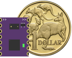
  • A tiny footprint - 13x17.8mm (0.51x0.70").
  • An easy to solder standard 2.54mm (0.1") pinout that can be used for either soldering directly to production boards or to header pins or wires for prototyping and breadboarding.
  • A user controllable LED (PWM, threshold, measurement or manual modes).
  • Device naming for easy recognition.
  • Precalibration for plug and play use, as well as auto user calibration.

All this is possible, without the need for any additional processing on your platform of choice.

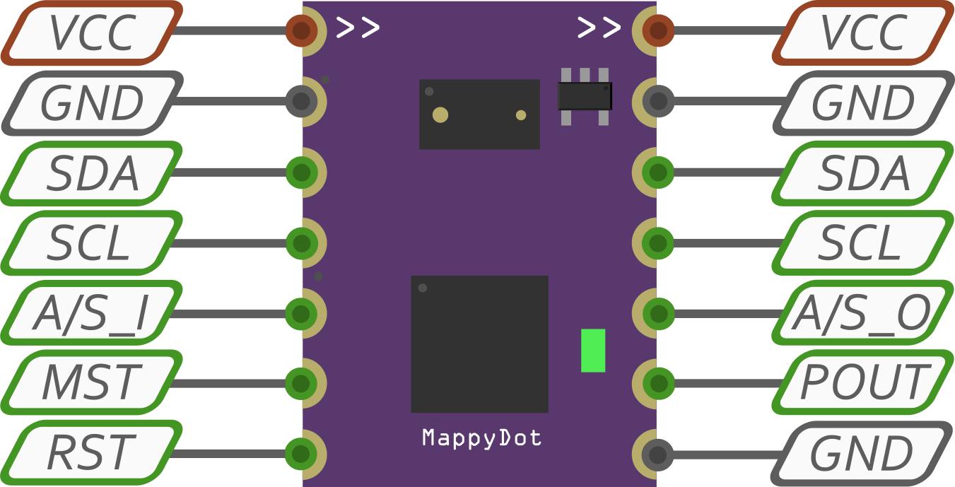
When the devices are connected to a power source (2.8-5.5V), they automatically initialise with an array of addresses, which can be easily scanned and polled to determine what is on their I2C bus from a controller. From there the devices can be read with a few lines of code.

Upon first power up, the MappyDot allows users to obtain an accurate 16bit position with two lines of Arduino code:

  Wire.requestFrom(address, 2);
  distance = Wire.read() << 8; distance |= Wire.read(); 

It's that simple, there's nothing else to it. No special libraries to load, just read a value from the I2C lines.

The default MappyDot firmware offers different operating modes from the MappyDot Standard mode:

  • Highly Accurate - 1.2m - 5Hz
  • Long Range - 2m - 30Hz
  • High Speed - 1.2m - 50Hz
  • VL53L0X Default - 1.2m - 30Hz
  • MappyDot Standard - 2m auto switching - 50Hz

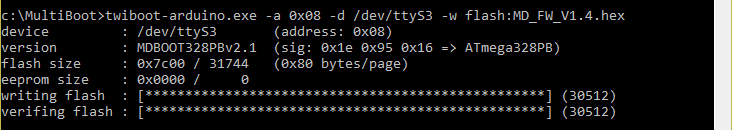
However, you can always tweak and update the firmware as you please via the I2C bootloader.

All MappyDot code, documentation and design on these project pages are licensed under the GNU General Public License (GPL) unless otherwise stated.

... Read more »

  • 1 × STMicroelectronics VL53L0X Time-of-Flight (ToF) laser-ranging module
  • 1 × ATmega328PB Microcontroller
  • 1 × MIC5365-2.8 Power Management ICs / Linear Voltage Regulators and LDOs
  • 1 × LED Fiber Optics / Emitters
  • 1 × Passives Resistors and Capacitors

  • Social Distancing Badge Design Prototype

    Blecky04/17/2020 at 04:27 0 comments

    In the last few days of the Social Distancing Badge Kickstarter we have the design prototype built up and working.

    Turns out LCD displays don't like hot air and like to shatter and leak. So yeah, don't get them anywhere near hot air.

  • Social Distancing Badge

    Blecky03/31/2020 at 10:01 0 comments

    We just launched a Kickstarter for the SensorDots Social Distancing Badge which is based on the MappyDots!

    The Social Distancing Badge is an Arduino based LiDAR badge that measures and displays the distance between you and other objects. It features a lightweight and low power design that can be pinned to your bag, backpack, shirt or even be used as a belt buckle or hair clip.

    Here's some more of the features:

    • Customisable Arduino based firmware (328PB microcontroller).
    • Eye-safe VL53L1 LiDAR sensor.
    • Micro USB serial and programming interface, as well as recharging.
    • Hackable GPIO interface.
    • 100mAh rechargeable button cell lithium battery.
    • Optional lanyard or safety pin attachment points (badge includes solderable safety pin to clip to a shirt or jacket and 3.2mm holes on the top).
    • 57mm x 38mm x 10mm badge size (thickness includes battery).
    • Low power and easy to read 4 digit LCD display.
    • Status/indicator LED and charging LED.
    • Mode switching button.

    Check out the campaign here - https://www.kickstarter.com/projects/sensordots/the-social-distancing-badge


  • SensorDots Port MuxR Kickstarter

    Blecky03/03/2019 at 07:32 0 comments

    We just launched our Kickstarter for the Port MuxR!

    The Port MuxR is like a KVM Switch but for electronics. It's a 8/16 channel, bi-directional, switched bus multiplexer that lets you branch out programming cables, logic analysers, debuggers and more.

    Check it out here - https://www.kickstarter.com/projects/sensordots/sensordots-port-muxr-a-kvm-switch-but-for-electron

    Here's some of the features:

    • Bidirectional data flow, with near-zero propagation delay through each FET switch.
    • Low ON-state resistance through switch ICs (Ron = 3 Ω typical, @ 3V) and optional series resistors on primary port pins.
    • Low input/output capacitance.
    • -2V undershoot protection prevents the FET (NMOS) switches from inadvertently turning on (when in off state) during signal undershoot events.
    • 0 to 5V signaling levels supported.
    • Supports both digital and analog applications.
    • USB serial/I2C slave control interface with selectable I2C addressing (the I2C port is master mode capable too).
    • Low crosstalk through switches when off.
    • 8 controllable Vcc pins (with LED indicator).
    • 3.3/5V Vcc selection header (with optional external power on adapter boards).
    • 8x8 pin or 16x4 pin multiplexing with additional primary port.
    • Included open-source .NET based control software.
    • Open-source Arduino control firmware for easy updating or modification to suit your requirements.

  • Buying Parts

    Blecky07/26/2018 at 09:42 1 comment

    What does an order for a tray of 490 Microchip 328PBs look like?

    Once you unbox the courier package, you get another box:

    Inside the box, so shiny:

    Opening the bag, you get the tray and some desiccant material:

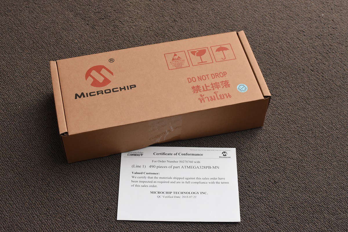
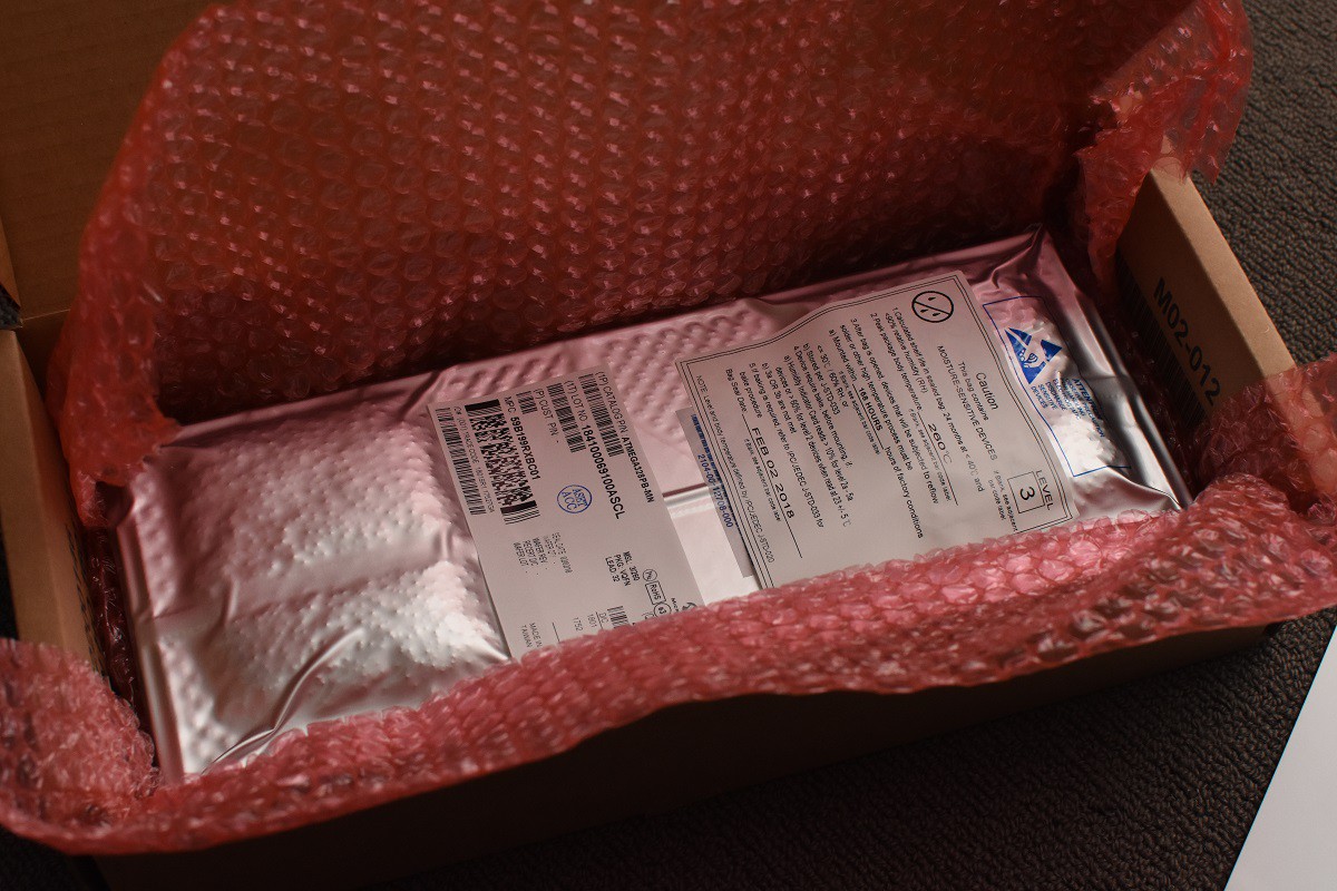
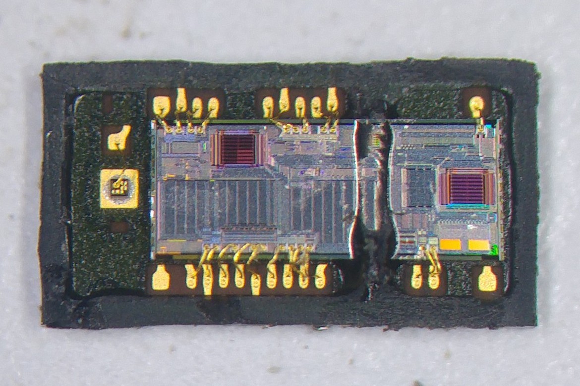
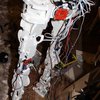
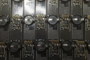
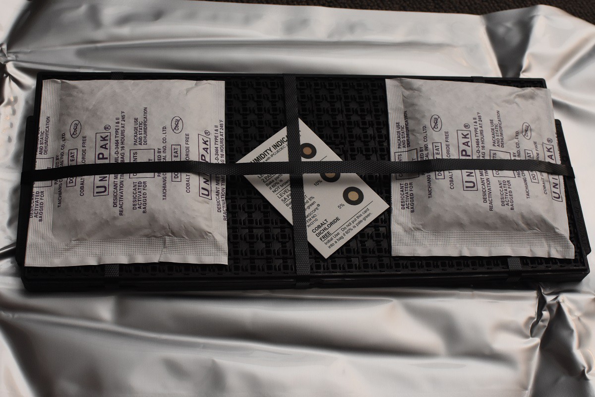
    And here are the microcontrollers on the tray:

    Delicious!

  • Pogo Pinlicious

    Blecky07/08/2018 at 05:39 0 comments

    Here is the programming board that is used to program SensorDots firmware and test that pins are working. Each board segment's supply rail is separately controlled by a MOSFET connected to a TI TCA6424A 24-bit GPIO expander.

    With this, each board is programmed and tested in sequence, which removes the need to gang up multiple programmers (as shown here for example - https://www.sparkfun.com/tutorials/233).

    Each pin under test is connected on the same bus to simplify wiring and remove the need for more bus expanders. The downside to this is that it cannot detect which board is shorting if there is a short on a pin, but this is pretty rare (and can be tested for by hand).

    Testing is performed by the onboard Teensy (to the right) and there is a ICSP header to connect to a programmer, as well as test routines in the firmware of the boards.

  • VL53L1X Teardown​

    Blecky06/22/2018 at 11:35 0 comments

    We've taken apart the VL53L0X sensor. So why not the VL53L1X?

    Here's the package with protective Kapton tape:

    Stop you're making me blush:

    Removing the IR filters, you can now see some optics. This is different to the VL53L0X sensor as this sensor has an adjustable field of view:

    Now taking the whole package apart, we have access to the die:

    Interestingly the sensor die is practically identical to the VL53L0X sensor except for some capacitors on the left.

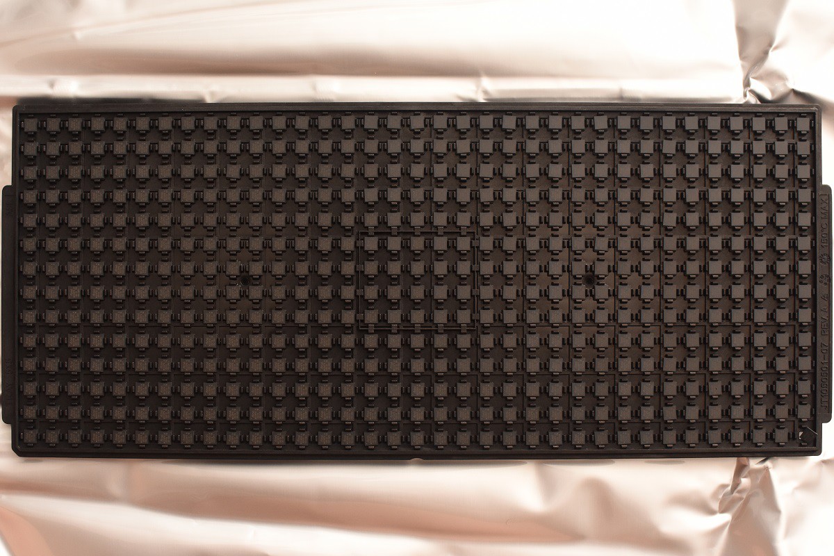
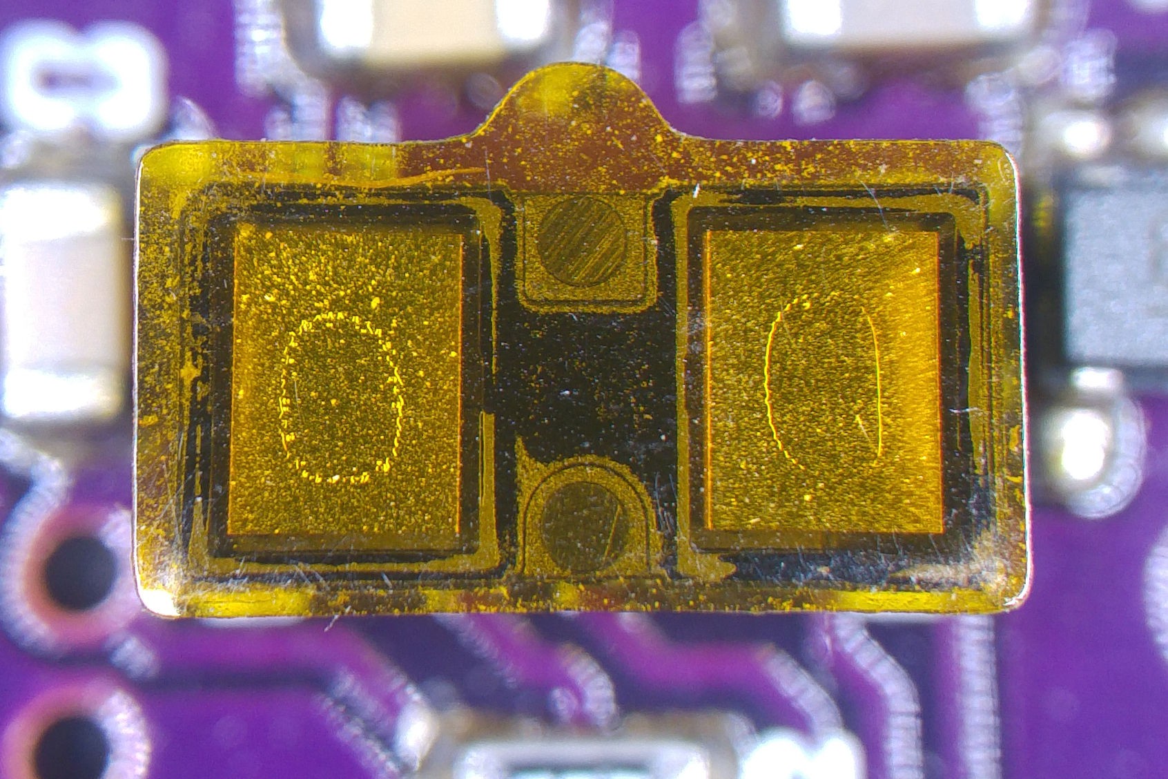
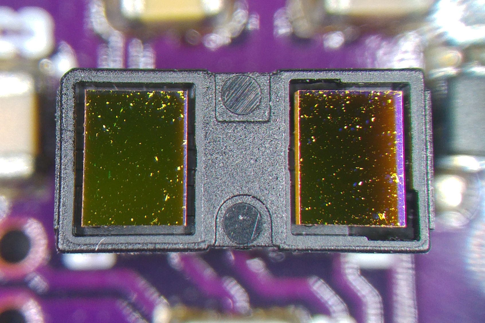
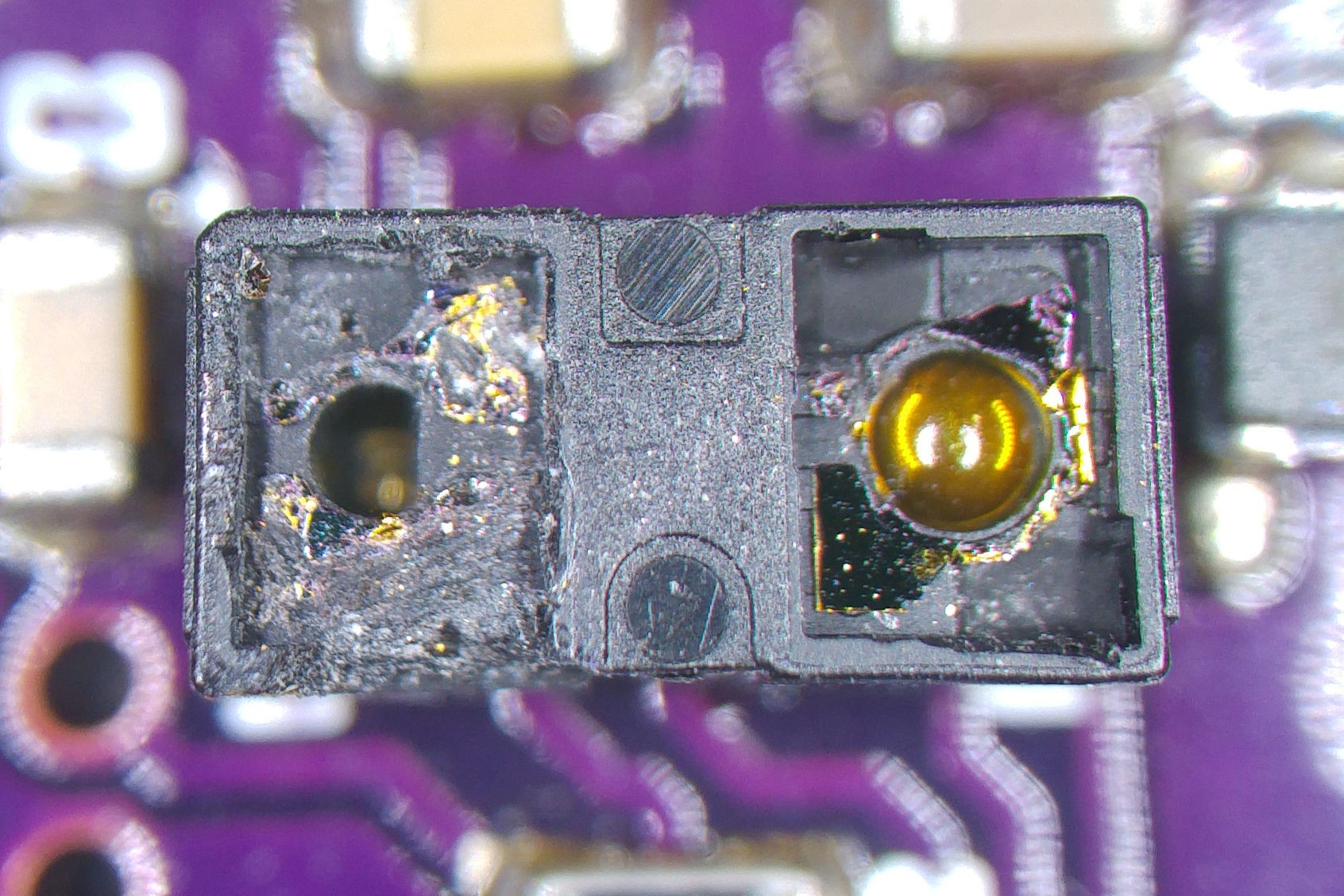
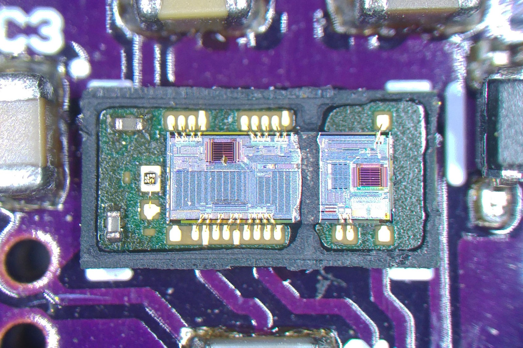
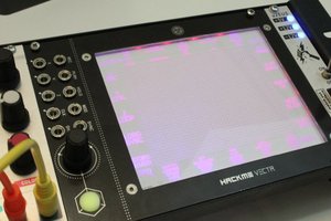
    Now it makes sense that the footprint on the VL53L1X is identical to the VL53L0X.

    It seems they are mostly making improvements to the front end avalanche diodes to allow them to be more sensitive to the returning light. Hence the similarities to the VL53L0X.

    Here's the block diagram of the VL53L1X:

  • Calibration-Free Dirty Environment Cover Glass

    Blecky05/28/2018 at 09:00 2 comments

    Check out the following ST video for a novel technique to remove the need to calibrate the VL53L1x sensor on the MappyDot for crosstalk if you are using a glass cover:

  • Picking and Placing

    Blecky05/13/2018 at 10:42 0 comments

    We have a new pick and place machine, the CHMT36VA.

    While some things are still being figured out with the machine, it's currently working quite well.

    Here's a quick demo video of the machine placing a few of the passives as a test run:

  • MappyDot Important Firmware Update!

    Blecky05/03/2018 at 12:40 0 comments

    If you wish to use the offset calibration or crosstalk calibration functions of the regular MappyDot (not Plus) you will need to upgrade to the 1.5 firmware release, as there is a bug that prevents the calibration data from being loaded.

    There is a firmware update guide available now which walks through the update process:

    https://sensordots.org/firmwareguide


    If you are running an older version, it's worthwhile to upgrade as there are a bunch of new features such as:

    • Auto address recovery.
    • Custom measurement mode profiles.
    • Soft interrupt command.
    • AmbientRateRtnMegaCps and SignalRateRtnMegaCps commands.
    • Tweaks to filtering.
    • And lots of minor bug fixes.

  • 1.4 MappyDot Firmware Released

    Blecky04/19/2018 at 13:52 0 comments

    The 1.4 version of the MappyDot firmware has been released with a few bug fixes and small features from the MappyDot Plus added in.

    The feature list:

    • Added soft interrupt command.
    • Added AmbientRateRtnMegaCps and SignalRateRtnMegaCps command.
    • Tweaks to filtering, no longer filters with measurement rate under 12Hz, now changes filter parameters when measurement frequency changes.
    • Reset default function now applies the changes to the active ranging (previous versions required you to save settings and restart the module before they became active). You still need to save the default parameters if you want them to be retained.
    • Reduction to API platform code to save code space.

    It's available in the repo - https://github.com/SensorDots/MappyDotFirmware

    Also here's an unrelated Litar string strumming gif (it is using the soft interrupt however):

View all 43 project logs

Enjoy this project?

Share

Discussions

qtron wrote 04/20/2023 at 12:28 point

U stated the various settings, inc Hi accuracy... how hi?

  Are you sure? yes | no

Jarrett wrote 08/21/2018 at 21:05 point

Hey, I have a few manufacturing questions.

With this:

https://hackaday.io/project/25571/gallery#17e3bb7d76898e5647fffc0f4762560f\

VS this:

https://hackaday.io/project/25571/gallery#45a209ee88f33c3812c15b70d5365d70

What's the justification for switching from two sets of mousebites per side to one set? Does it not allow the board to flex from side to side too much?

And then with your test jig, here:

https://hackaday.io/project/25571/gallery#39755d3e5ac2ca4936e50d74350c2795

How well do the pogo pins handle the castellations? Do they not slip out the side? Does the previously mentioned board flexing not cause issues?

  Are you sure? yes | no

Blecky wrote 08/22/2018 at 08:10 point

I've always stuck with one set of mousebites in the center (top and bottom of each board). The first image has had the mousebite filed down for cosmetic purposes. I may switch to two however to make cleanup easier as some copper does get in the mousebites making them harder and less precise to snip out of the panel. The only thing to consider is that the board doesn't vibrate too much in the PCB mill. Confirm with your fab before going ahead with this, they'll tell you what works.

The programmer has a perspex sheet screw clamp (5 screws; one each corner and one center) which has cutouts for each board that sit around each of the board edges (and avoids the parts). This provides uniform clamping for each board, so flex isn't an issue.

As for the pins slipping it would depend on the type of pogo pin you choose. The ones I have don't experience any issues with slippage as each individual pin doesn't have much clamping force to cause this. The springs in the pogo pins are pretty light. The solder keeps them pretty rigid as well.

  Are you sure? yes | no

Jarrett wrote 08/24/2018 at 16:38 point

Cool, thanks!

  Are you sure? yes | no

[deleted]

[this comment has been deleted]

Blecky wrote 11/18/2017 at 23:05 point

Ah good catch. I do explain the byte ordering in the documentation on the SensorDots site, but I have tweaked the "one liner" Arduino code to remove this ambiguity.


Thank you!

  Are you sure? yes | no

jean.perardel wrote 09/12/2017 at 08:19 point

Really cool sensors! 

Thanks for sharing! 

  Are you sure? yes | no

Blecky wrote 09/12/2017 at 10:20 point

Thank you Jean :)

  Are you sure? yes | no

Dan DWRobotics wrote 08/23/2017 at 18:30 point

This looks like a very interesting project indeed. I imagine you would be able to mount multiple units on a rotating cylinder and pole the units in a scanning motion as they traverse the forward facing plane. In effect you could make a rudimentary imaging sensor, much like the lidar on the boston dynamics bots. I imagine the data would be usable despite the wide angle of focus by combining data from each section of the scan to get a map of distances that would translate to 3d map of distances of everything in a forward facing 2 meter arc. Would be most useful for a full size robot!!

  Are you sure? yes | no

Farid Stein wrote 08/21/2017 at 20:55 point

This project looks extremely interesting and I can't wait to have a look at your firmware. I use the sensor myself in some projects and have had my share of trouble with it.

Any estimation when you will make it public?

  Are you sure? yes | no

Blecky wrote 08/27/2017 at 16:00 point

Hi Farid, the source code will be made public at the end of the month to coincide with the product's release :)

  Are you sure? yes | no

Cody Barnes wrote 08/21/2017 at 20:53 point

This could be useful to my work on the Eyedrivomatic project as a safety to prevent people from driving wheelchairs off of curbs or worse. What is the accuracy and resolution in "Highly Accurate" mode?

  Are you sure? yes | no

Blecky wrote 08/27/2017 at 16:19 point

For something like that I'm assuming that you would be aiming to detect a change in distance as you reach the curb's drop off point. The main thing to consider is the slightly limited ranging capabilities of the VL53L0X sensor outdoors.

It does start to degrade on bright days (it will still work, but the standard deviation increases). Temperature can also give a few cm's of error, however this can be re-calibrated easily though with a command (say every few minutes).

For shorter measurements less than 60cm on a bright sunny day (I haven't had any recently to test this myself), the highly accurate mode should give you around about +-4cm when measuring distance from the pavement. This is a worst case estimate, but generally it will be better than that, especially for shorter distances.

  Are you sure? yes | no

Ted Yapo wrote 06/28/2017 at 13:07 point

I looked at the VLX53L0X datasheet, and the field-of-view is 25 degrees, which seems wide if you want to use them in a narrow array.  I guess you could angle them into a coarse array, but I wonder about collimating optics of some sort.  I saw the application note about issues with crosstalk even using flat windows, so I'm not sure using a common lens system would be practical because of reflections in the lens system.  Ideally, you could slap a 12.5mm webcam lens on there, but it probably wouldn't work. The part is probably too small to easily fit separate lenses on top.  I guess it could also make the laser less eye-safe. What is your thought?

  Are you sure? yes | no

Blecky wrote 06/29/2017 at 11:52 point

Hi Ted,

I will be modelling these effects with the prototype boards to see what works and doesn't work. The main thing is that you would be using this for collision avoidance, so 25degrees is useful as you don't require as many devices to cover an entire area. In terms of reducing cross talk for narrower applications, shielding these overlaps with non reflective black surfaces will remove cross-talk effects in these cases.

I may consider an optional tubular add on for these types of requirements.

  Are you sure? yes | no

Corcovado wrote 11/26/2017 at 13:39 point

I'm likewise wondering if a collimating lense or lenses could be added. Have you proceeded with this?

  Are you sure? yes | no

deʃhipu wrote 06/21/2017 at 11:36 point

I see someone found the VL53L0X sensor! Personally I'm mostly interested in how you are going to achieve the levitation effect ;-)

  Are you sure? yes | no

Blecky wrote 06/21/2017 at 12:39 point

;)

  Are you sure? yes | no

Similar Projects

Does this project spark your interest?

Become a member to follow this project and never miss any updates