 Dennis
Problem:
Have you ever needed to crawl under your vehicle to see where that leak is coming from, or maybe you’re a home owner that may need to crawl into a small dark crawl space and push your way through the spider webs to investigate a possible busted pipe? Or you could be a law enforcement officer that needs to look under a suspicious vehicle for possible drug smuggling.
Solution:
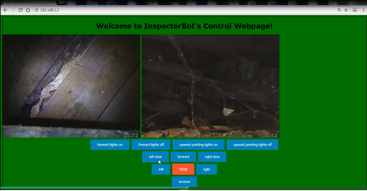
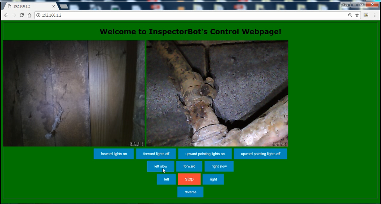
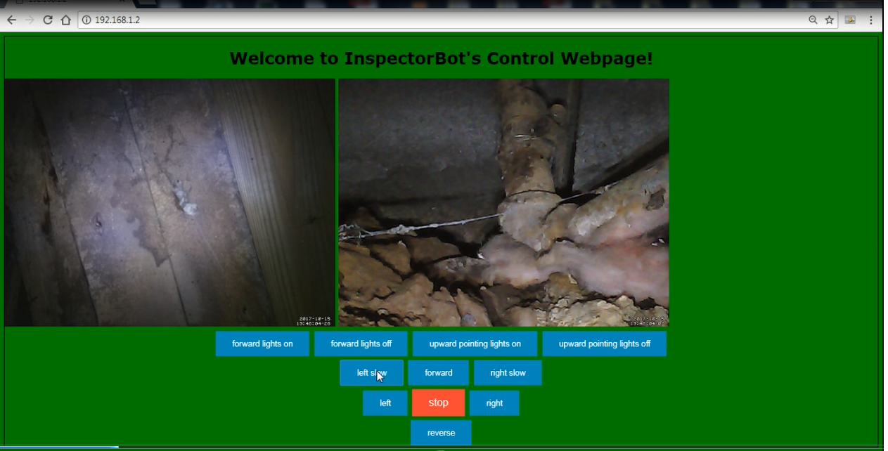
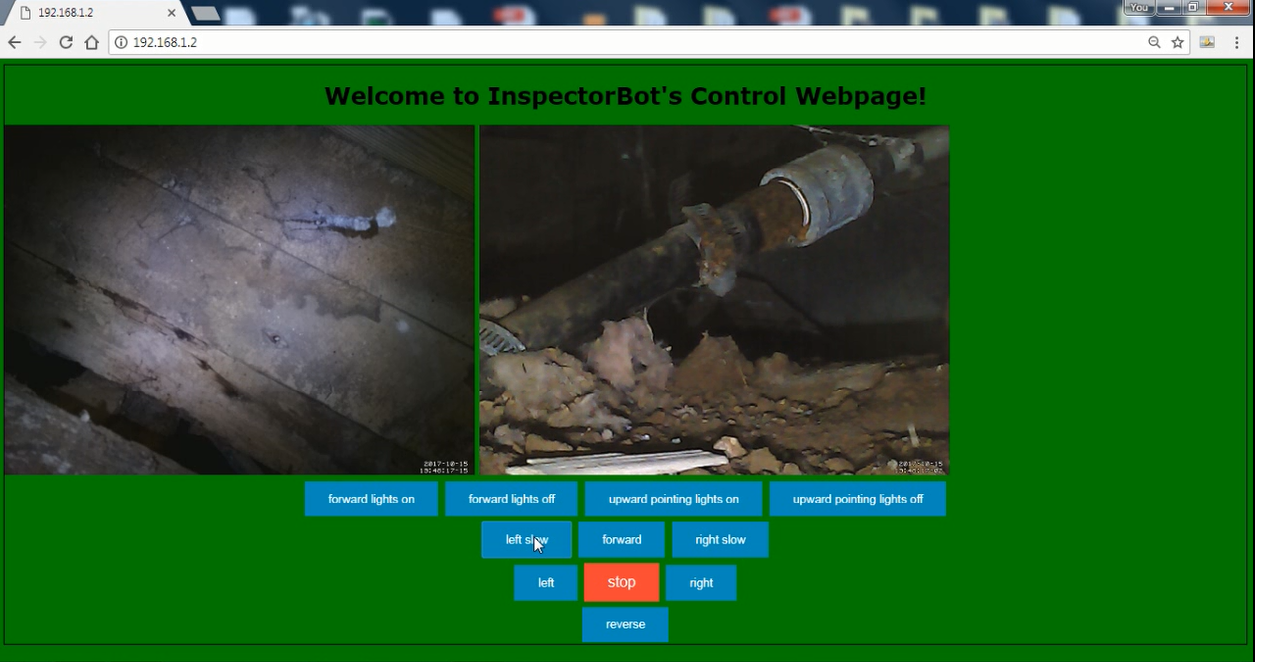
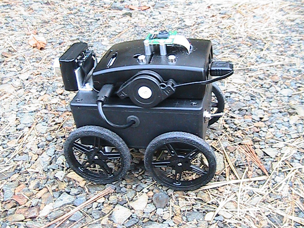
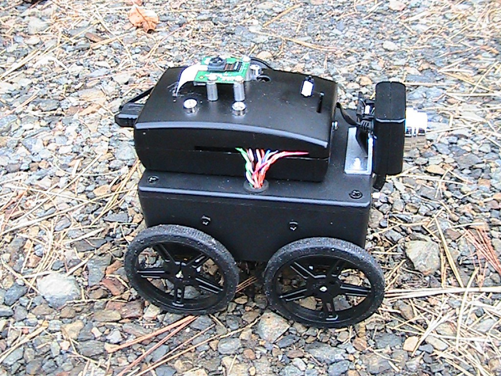
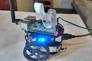
InspectorBot is a small, low cost open source tele-operated robot with an upward-pointing high definition camera to allow easy inspection of any surface above the robot. A second forward-pointing low definition camera will be used to allow the user to drive the robot to the desired location. InspetorBot will be built around the ever-popular Raspberry Pi with P2P (Point to point) wifi and a built in website to allow InspectoBot to be controlled from any smart phone or web enabled device in any location.
Project agenda:
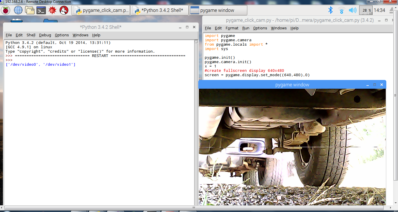
During the development of InspectorBot, I started thinking about how InspectorBot could be commercialized and how could it benefit people in general. There are military, law enforcement and the obvious border patrol applications, but I really want InspectorBot to be able to help the average citizen to be able to start businesses and work toward financial independence. One area would be auto auctions. A lot of small automotive dealerships purchase used cars at auto auctions. An InspectorBot would allow the dealer to take a better look under the vehicle and have a better idea of the vehicle’s value before they bid.
Another area I believe would have the greatest possible opportunity would be the idea of an under building survey. The concept is to use an InspectorBot to take a series of high definition images from the crawl space of the underside of the building. Use an application to “stitch” all of the images together to generate one complete high definition image of the underside of the building. There is no business that I’m aware of that presently provides this service, but what is under the building is as important as what is above the building.
Who would be the customers?
The most obvious customers would be in the real estate industry. I cannot imagine that any individual that is looking for a new home would not be interested in what is in the crawl space of a potential new home, not to mention a building inspector could have actual data about the crawl space. If the service was available, mortgage companies and banks would be interested in any information to protect their investment, plus the data could be used to help assess the value of the home. The addition of sensors could also allow dangers such as radon gas to be exposed. This could help protect the family that will be living in the new home.
Another possible use is to inspect a commercial building before it is renovated. Often when older buildings are renovated, unexpected dangers, such as asbestos-covered pipes and insulation, is encountered. An under building survey could expose these dangers before any workers are exposed.
With lots of possible customers in a new and presently untapped field of under building surveys, there are opportunities for entrepreneurs and innovators to start new and profitable businesses in a whole new field with just an InspectorBot and a software application to stitch the images together.
Build agenda:
After I built the proof of concept unit with extra parts I had, I decided the new build would be more reproducible. Here’s a build agenda to breakdown the new InspectorBot’s build:
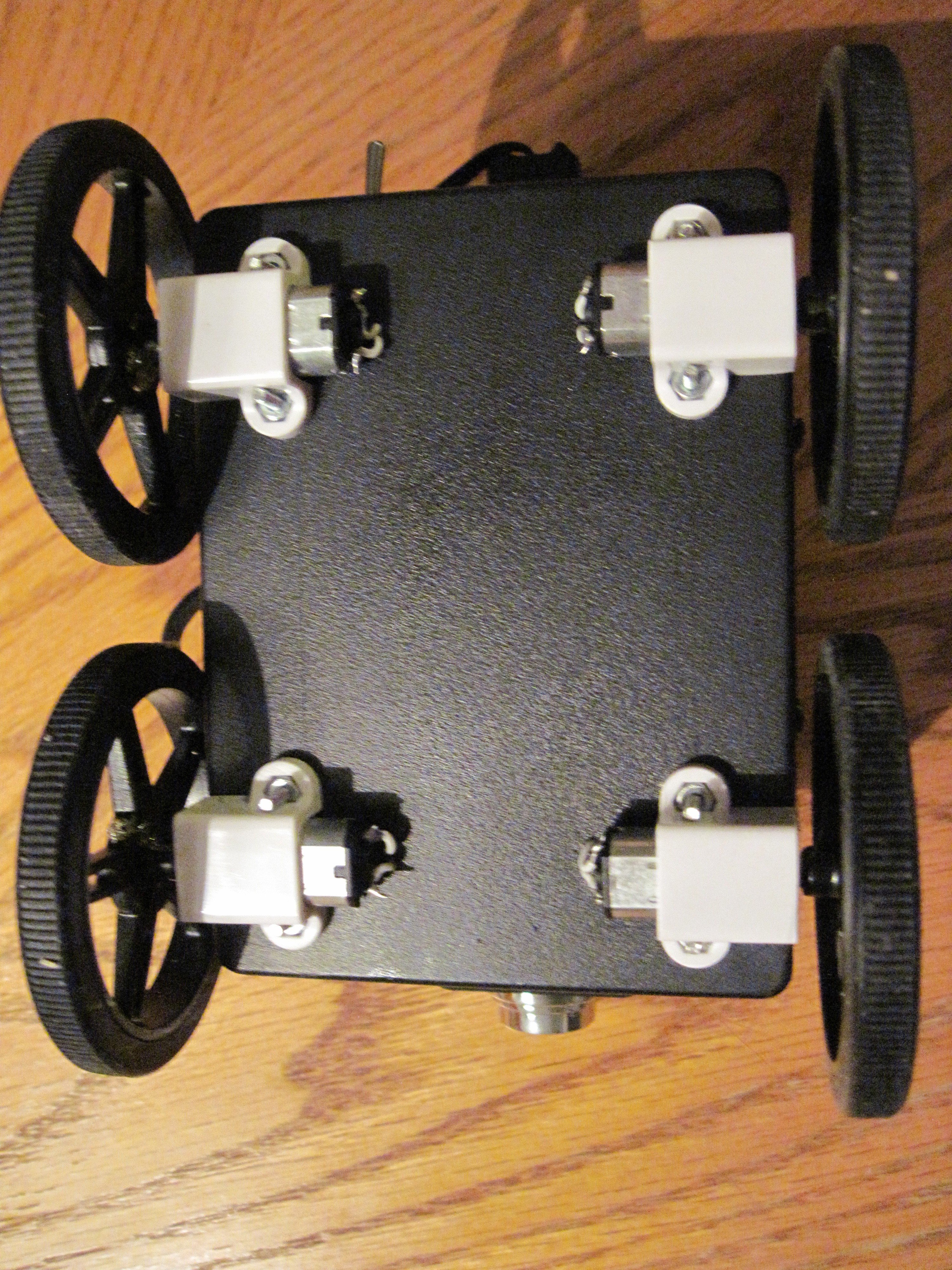
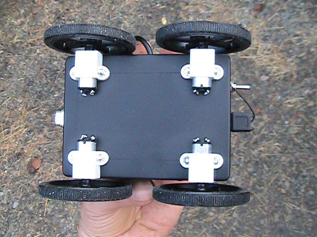
- For the new build, select easily available parts to make InspectorBot easy to reproduce.
- Setup and test low definition camera.
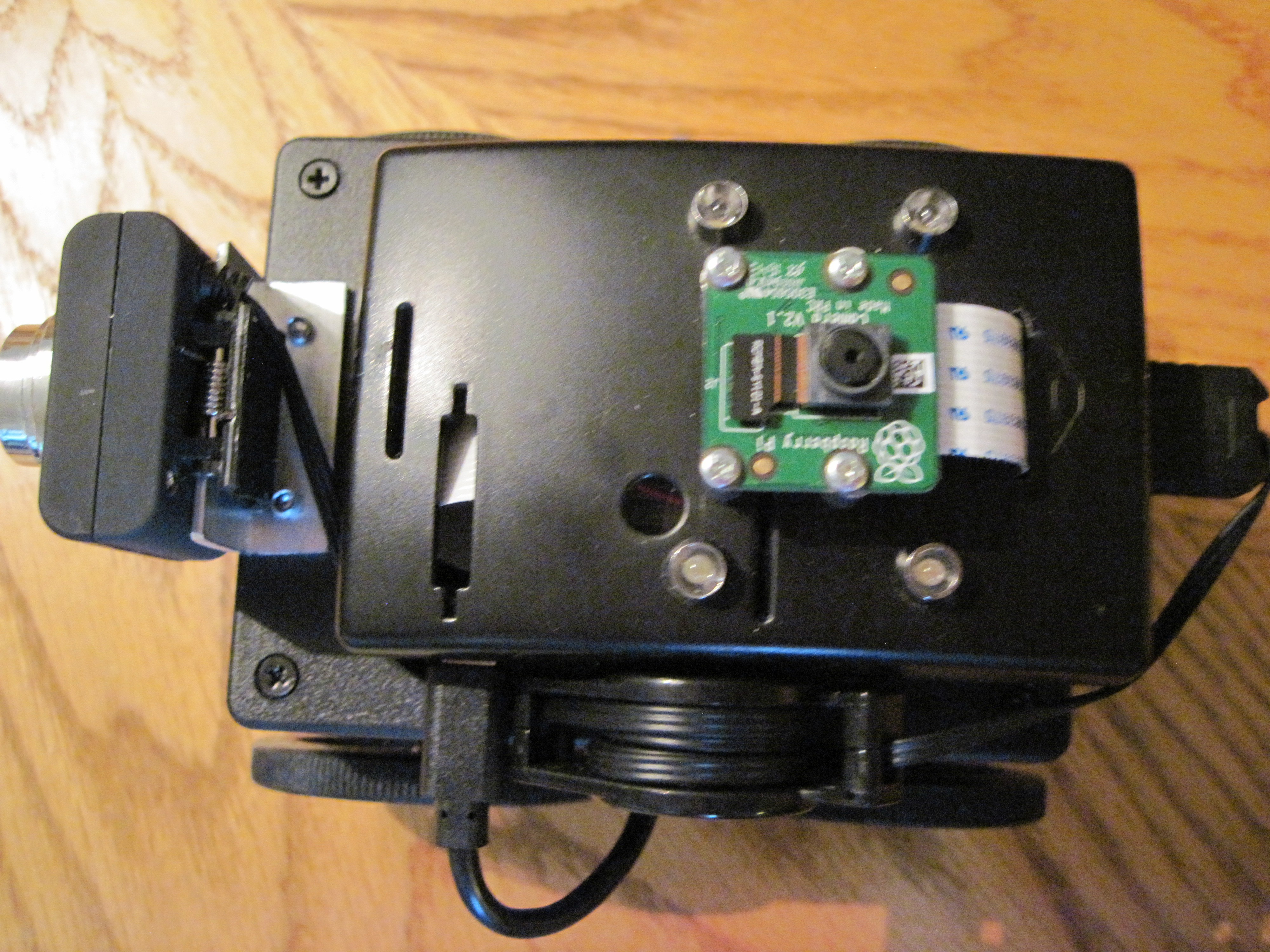
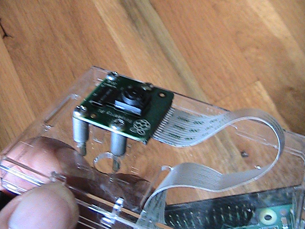
- Setup and test high definition camera.
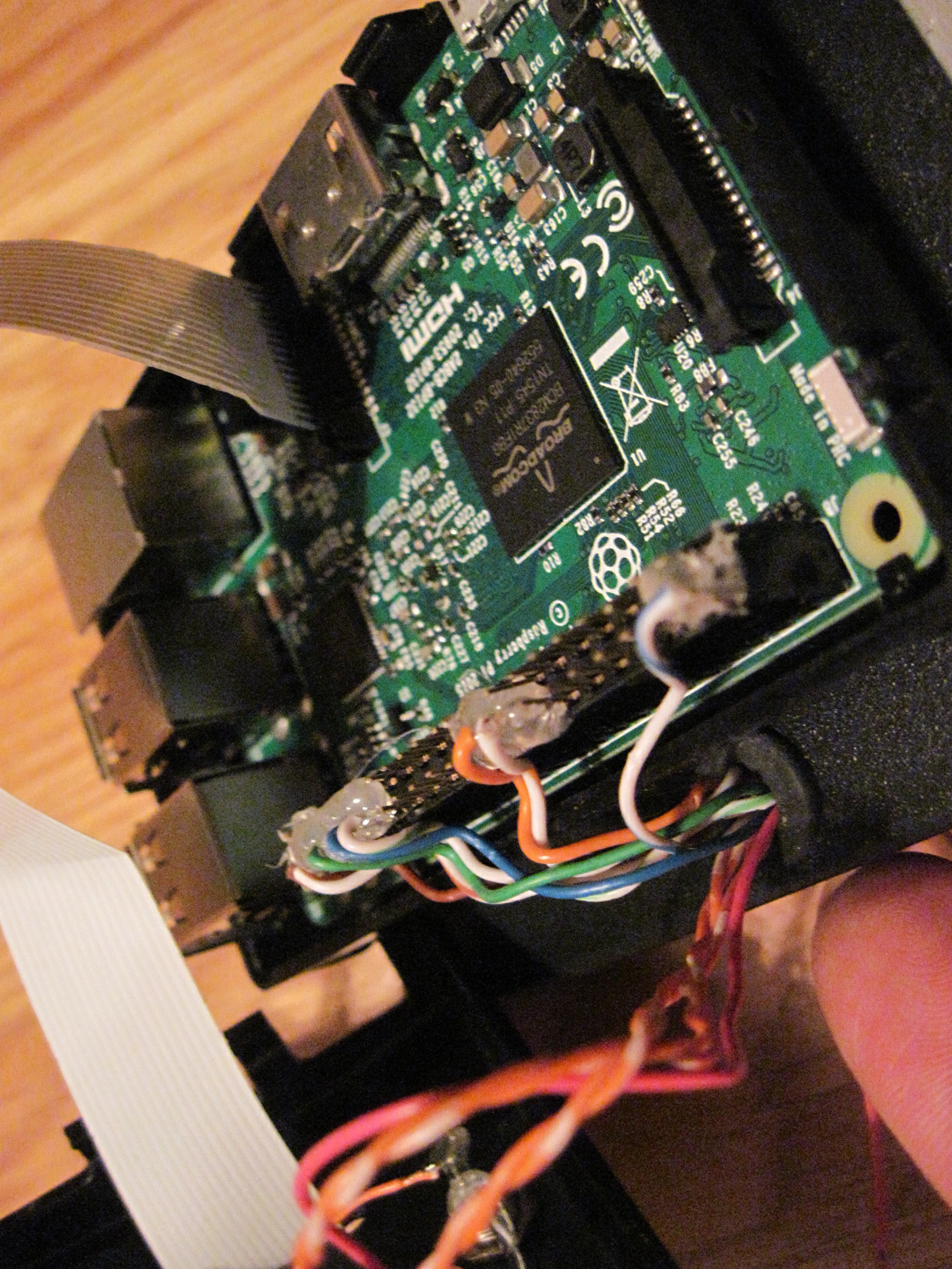
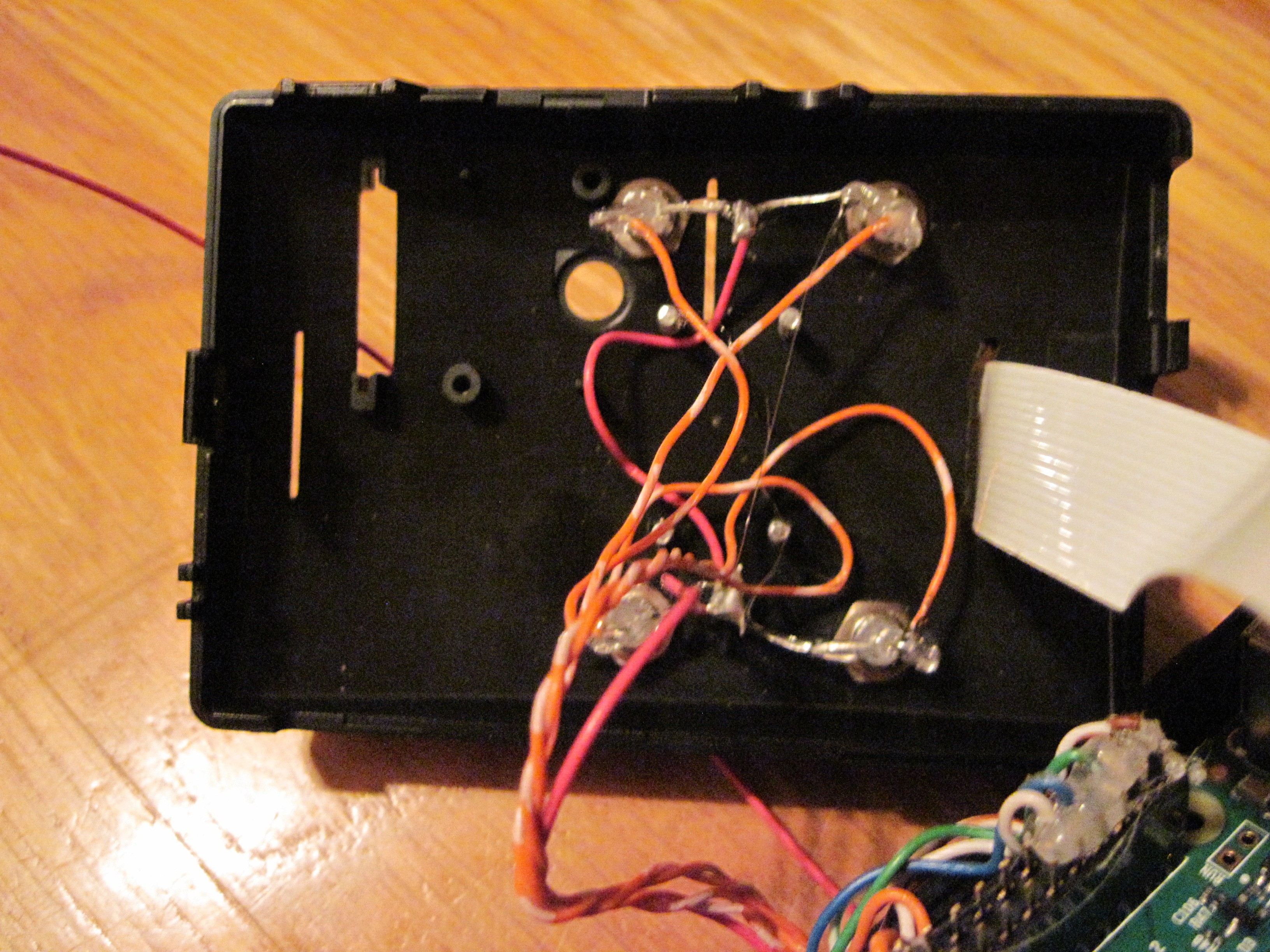
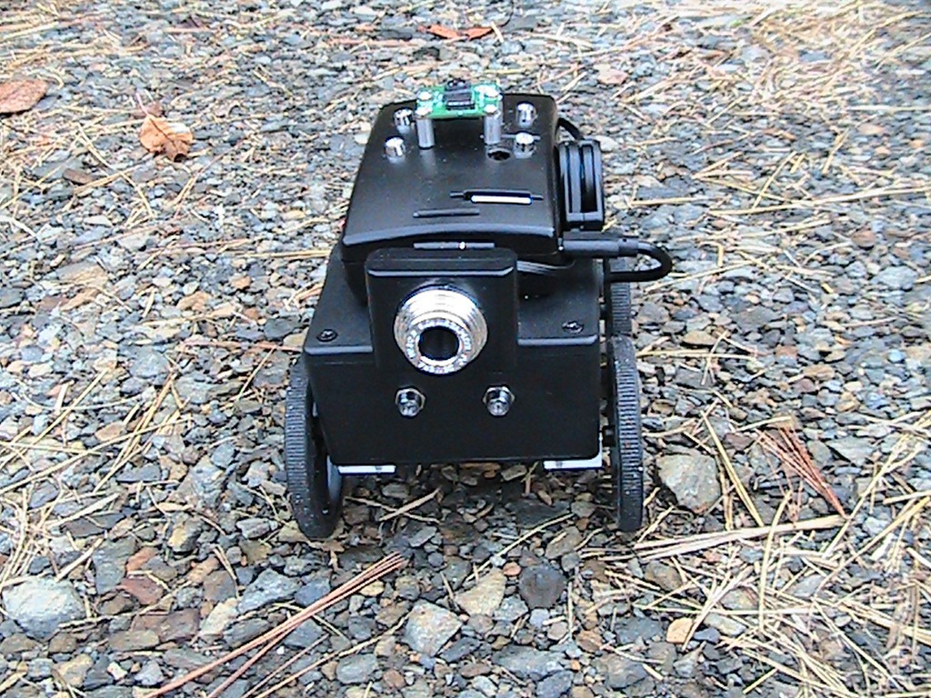
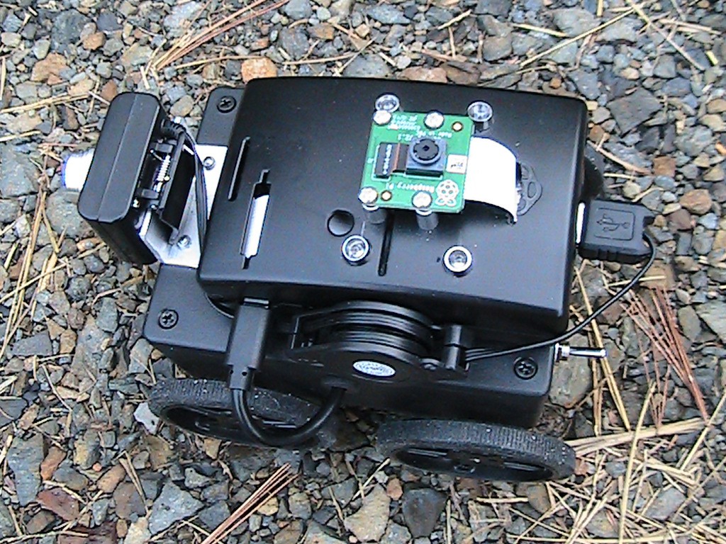
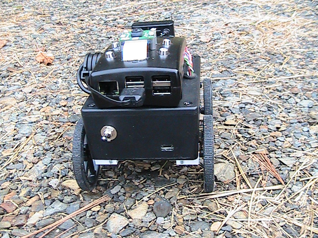
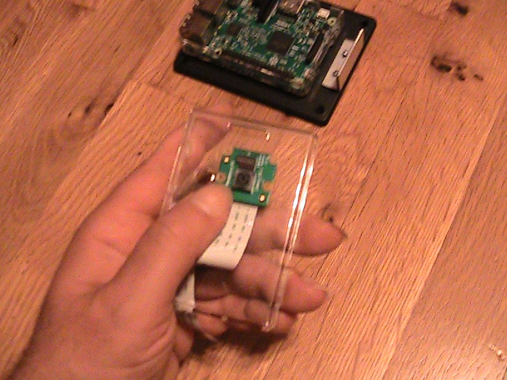
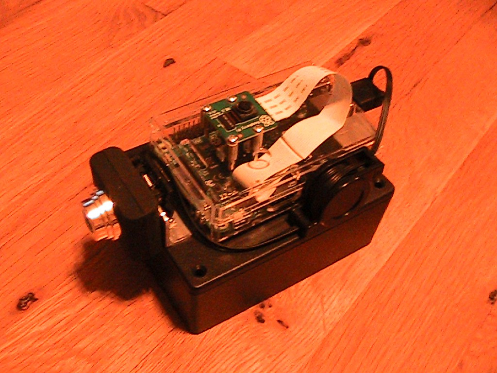
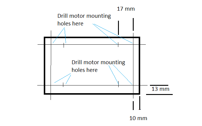
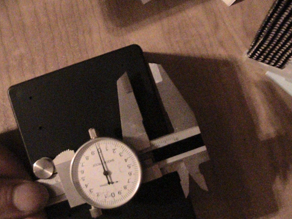
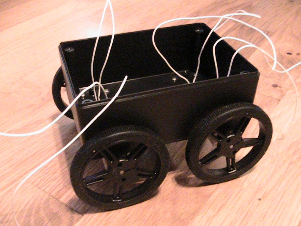
- Start the build around a Raspberry Pi. Install both cameras and Raspberry PI on a box used as the main body of the robot.
- Use Python to develop an easy way...
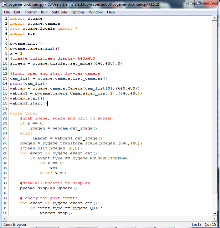
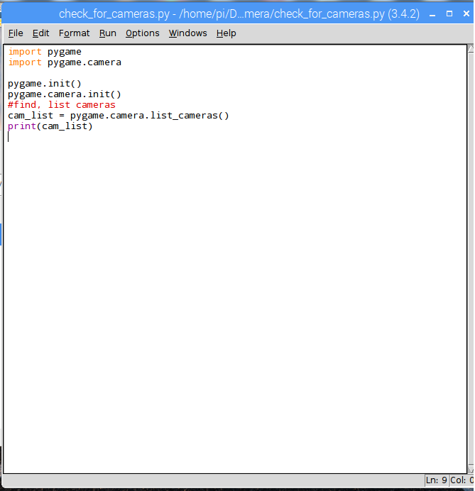
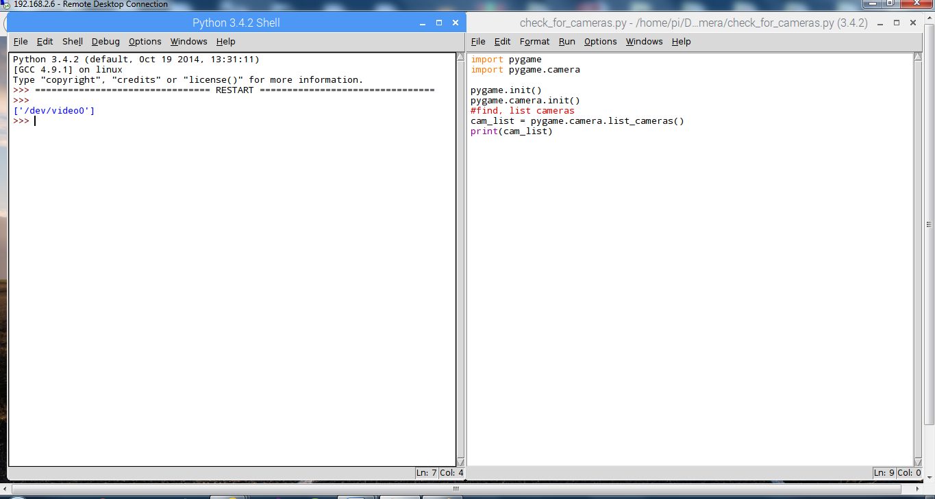

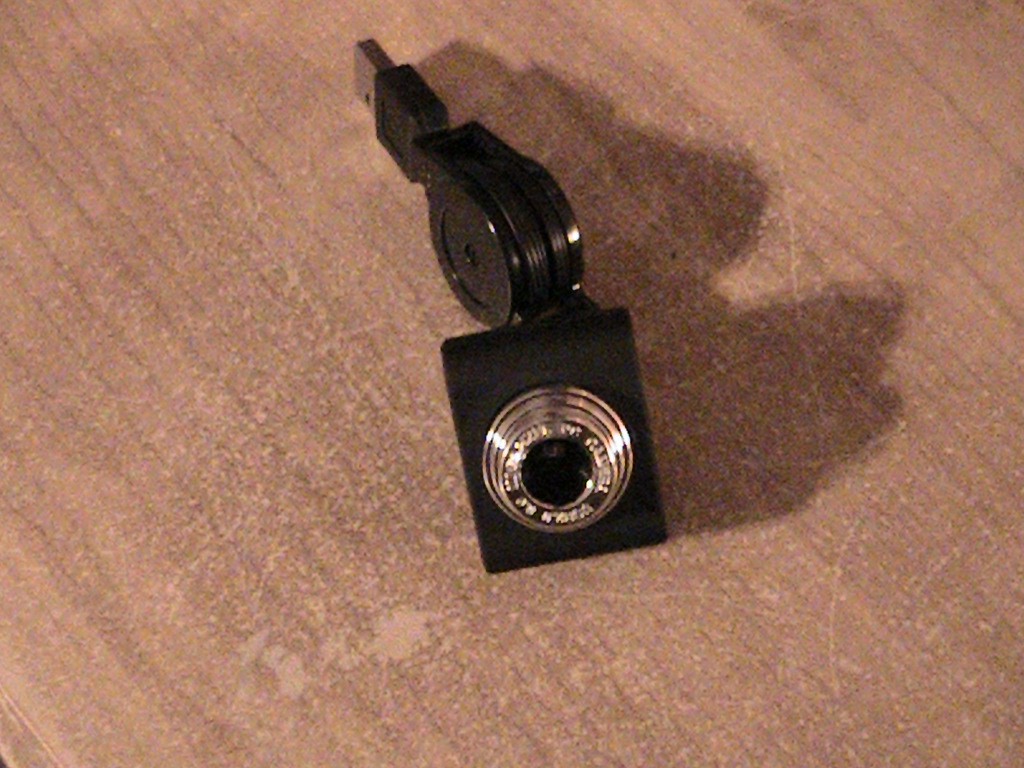 I wasn’t sure if the camera would work with a Raspberry PI
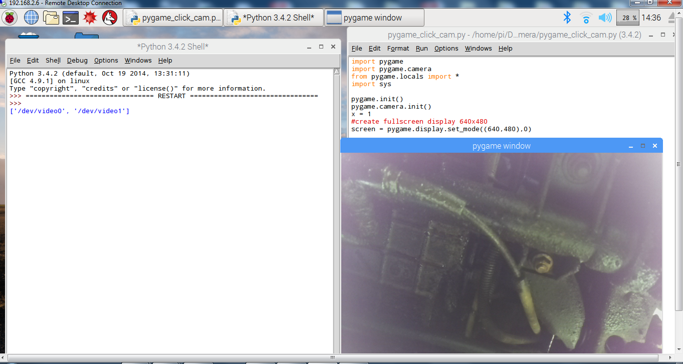
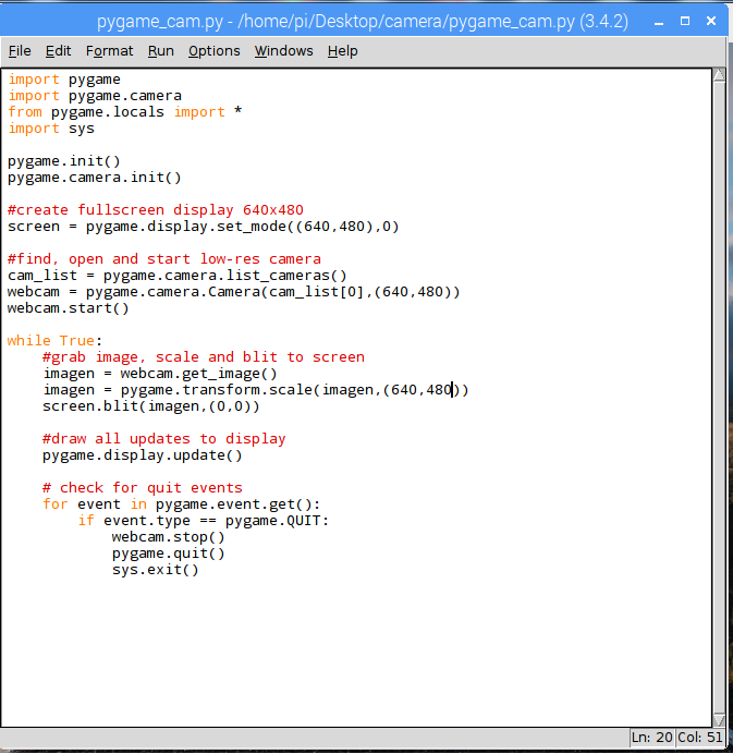
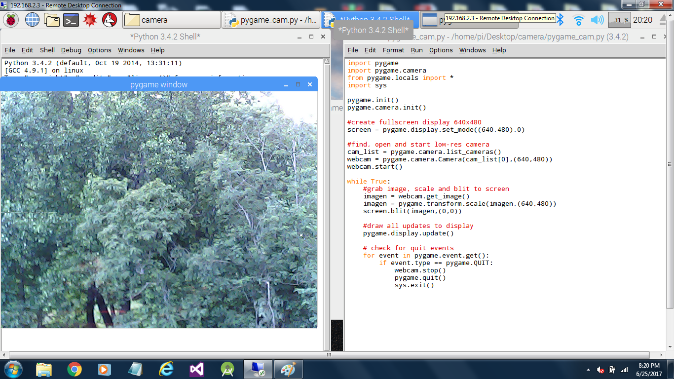
so I wrote a short program using Pygame to test it. Below is the program and an
image of the program running with the mini camera plugged into one of the
Raspberry PIs USB ports. It works well with a Raspberry PI.
I wasn’t sure if the camera would work with a Raspberry PI
so I wrote a short program using Pygame to test it. Below is the program and an
image of the program running with the mini camera plugged into one of the
Raspberry PIs USB ports. It works well with a Raspberry PI.


 Brenda Armour
 Max.K
Max.K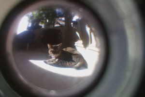
 DrYerzinia
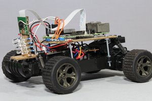
 Norbert Heinz
Great project, thanks!
If you're worried about your moms getting scared by snake skins, just go to youtube before showing her what is under the house! Search for "brave village girl catch snake," that will help teach her to be more confident. For most of us, the snake under the house is just a garter snake!