 Elliot Williams
What the heck am I doing? The whole point of the flyback/inductor trick is to make a step-up voltage converter, and I'm running a 1.8 V LED off of a 3.3 V battery...
Well, whatever it's doing (providing more reactance?) it's doing a good thing: pulling the inductor out and just driving the LED straight burns 60 microamps. It may also be a fair bit brighter, but that's not really the point of this exercise.
I called this done, and now I need to play around with the circuit some more. Sigh.
---------------
Edited to include Ted's constant-current comparison: one LED, one datapoint.
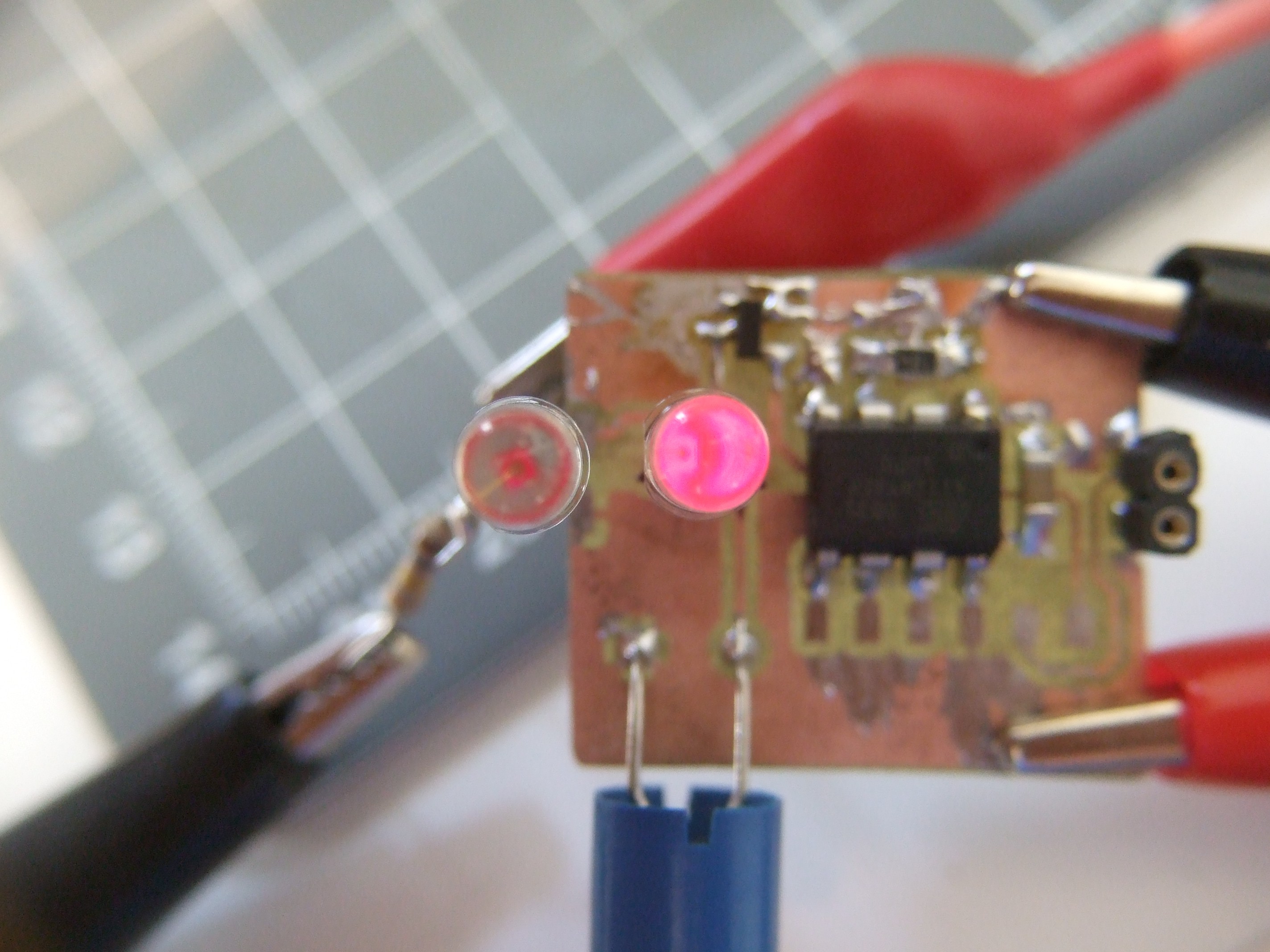
Two LEDs from same tape reel. Left driven at constant 11.1 microamps through a 150k resistor. Right driven by pulse circuit at 9.1 microamps (including the ~5 microamps eaten by the AVR and transistor -- so maybe 4 uA avg for the LED).
I couldn't even tell that the left LED was on until I cupped my hand around it, as I'm doing in this image. The difference looks about like this to my eyes as well -- they're strikingly different. One is "bright" and the other is barely on.
As Ted points out, running the LED with milliamp peaks seems to make them run a lot brighter. Woot.
Neither of these will illuminate anything, mind you. In a dark room, you can see the brighter LED easily, but it's not throwing enough light to read by or anything. Still, if you just want a marker, it's perfect.
Discussions
Become a Hackaday.io Member
Create an account to leave a comment. Already have an account? Log In.
I think your confusion can be solved by realizing that it's not really a boost convertor, at least not any conventional kind. I haven't really worked out any math or simulations, but I think it's more similar to an inverting convertor, so it can generate voltages smaller or larger than the supply voltage, as the load demands. So for an isolated load like the LED, it can be a boost or buck converter, and be more efficient than a resistor.
Are you sure? yes | no
That's a great comparo. In addition to constant current, you could also try subsequently smaller resistors and some PWM to see how that affects efficiency.
At the end of the day, what strikes me as fun about the inductor solution is that it solves a pair of design problems at once -- how to deliver a tiny current without burning it up in a resistor and how to bump up the voltage when the battery is nearly done.
The downside, I guess, is that the inductor is a relatively large part.
Are you sure? yes | no
Thanks for running the test!
I like this result because it counters the intuition that you can do the same with just a resistor. Of course, we're comparing a linear power supply to a switching one (crude as it is), and you're right about the boost with low input voltage, and there's probably some in-between point with resistor limited PWM (I touched on it here https://hackaday.io/project/11864/log/43372-microcontrollers-101) . But somewhere, there's that nagging voice that says a microcontroller is way too much overhead to dimly light an LED, and a resistor and battery are all you need. It's good to see someone replicate the experiment like @jaromir.sukuba did for the earlier flying capacitor version.
Are you sure? yes | no
So, here's the real test: run an identical LED at a DC current of 9.9 uA (or whatever your pulse circuit consumes on average). If the pulsed one is brighter, you've gained something. Depending on the LED, you may or may not gain anything - the principle being that some LEDs are very inefficient at low currents, so driving them with larger pulses saves energy. Here's my comparison at 3.7 uA:
The LED on the left is driven with 3.7uA DC through a resistor; the one on the right uses the TritiLED circuit at a total draw of 3.7uA - interestingly, this includes around 2.9uA just for the PIC. So, you could run either one for over 6 years on a CR2032. In this case, you get more brightness out of the pulsed one, and get the benefit of a microcontroller - for blinking modes, etc. At higher currents, the PIC overhead is less, but the DC-driven LED becomes more efficient. For some LEDs you may not be able to find a point where the pulsed one is more efficient - it depends on the LED efficiency curve, LED chip size, inductor properties, etc.
In this test, both LEDs are held in alligator clips; swapping them produces the same results (the result is not due to LED-to-LED brightness variation). The camera also used a 1/2 second exposure to avoid distorting the brightness by catching just one bright flash. In this case, it could be over or under-estimating the brightness by 1/8 (catching 7 or 9 pulses in 0.5s instead of exactly 8), which is less than the observed difference.
These particular LEDs don't show a dramatic gain, but they are easy to solder :-)
Update: I recruited an assistant to evaluate the relative brightness of the two LEDs while I varied the DC current. She said the two looked equally bright with a DC current of around 12 uA (I did several trials, approaching from high and low currents). This would mean you can get about 3x the battery life for the same brightness with the pulsed one.
Are you sure? yes | no