0%
0%
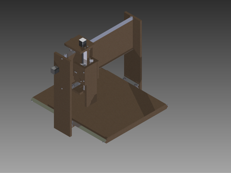
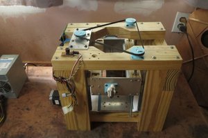
CNC Mill
A (hopefully) simple CNC mill built without welding
 Steel_9
Become a Hackaday.io member
Already have an account? Log in.
Just one more thing
To make the experience fit your profile, pick a username and tell us what interests you.
Pick an awesome username
hackaday.io/
Your profile's URL: hackaday.io/username. Max 25 alphanumeric characters.
Pick a few interests
Projects that share your interests
People that share your interests

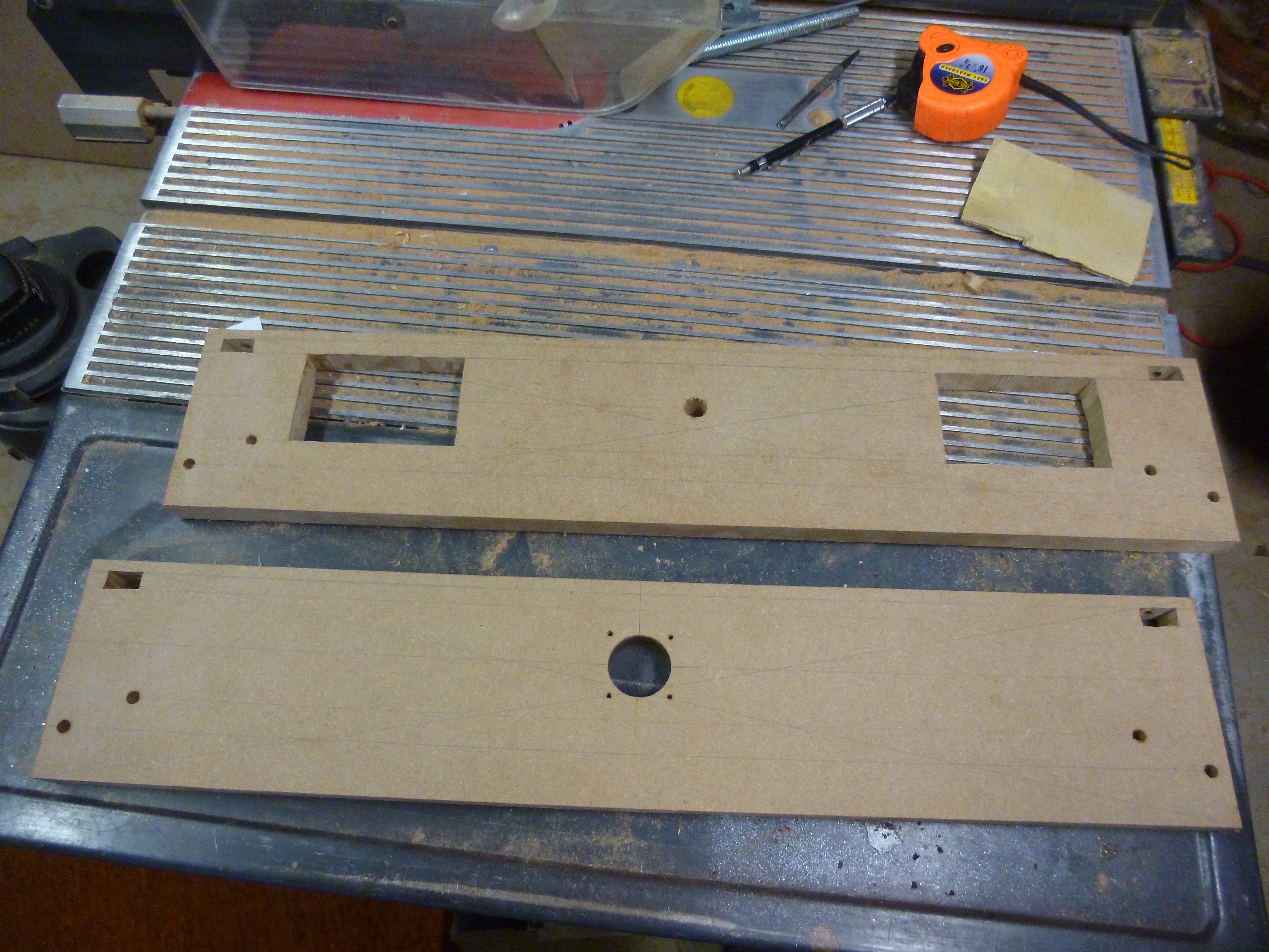 On top is the original. on the bottom is the new version. The cutouts are for a power switch and an outlet.
 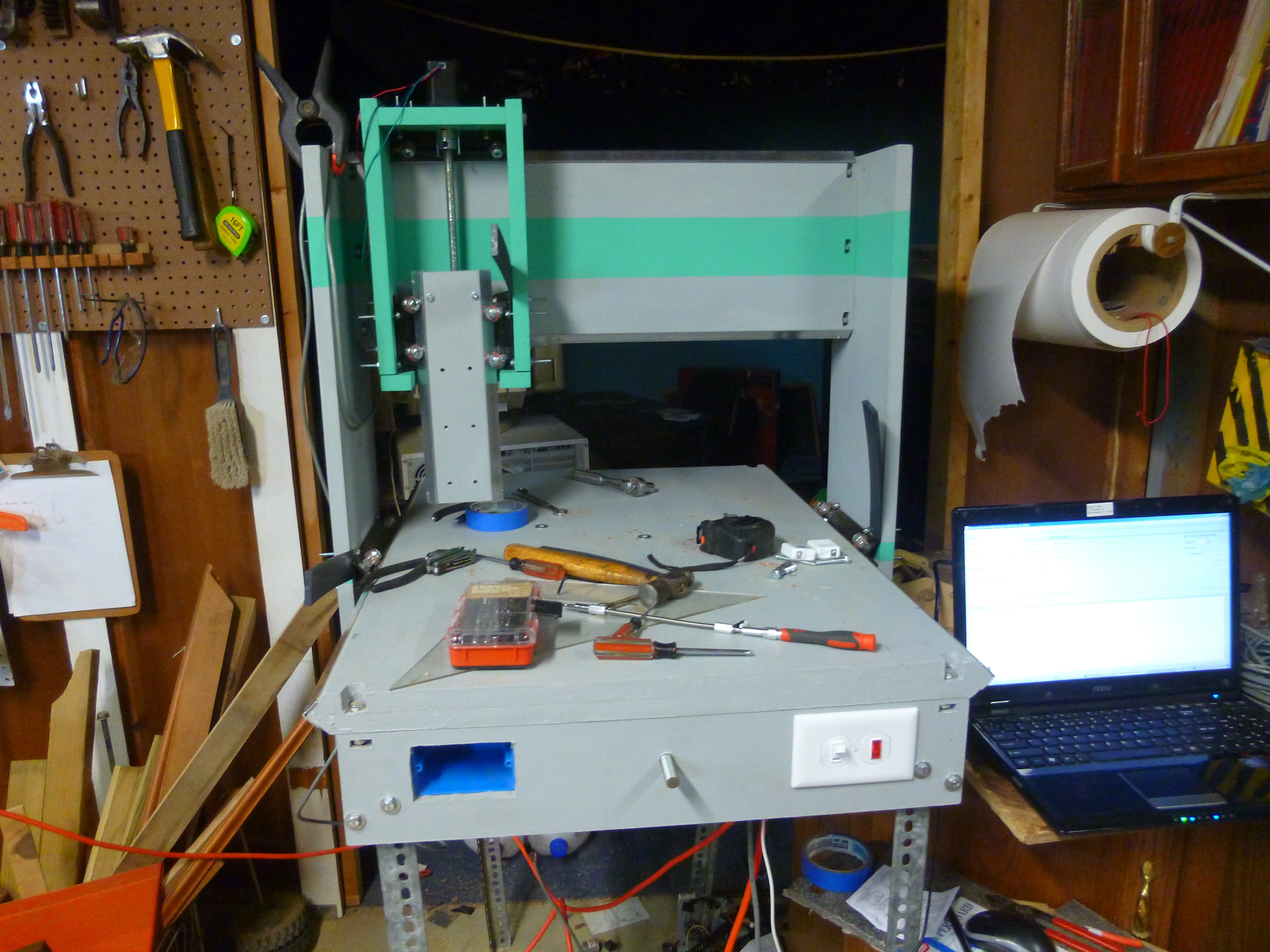 Part of this might be from my habit of using any available flat surface as a workbench, and not putting away the tools I am using until after I used them for the third last time.
 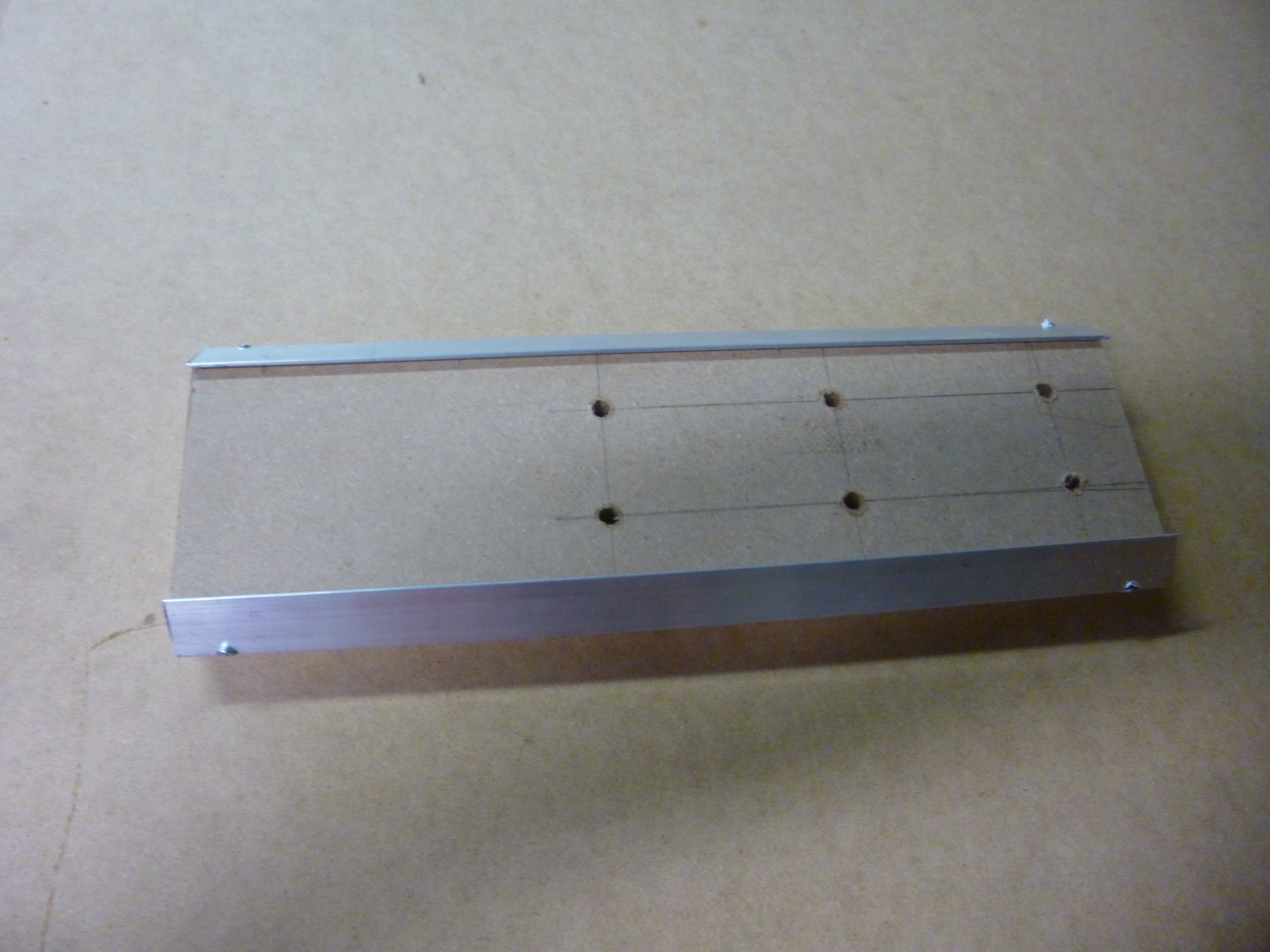 I started with the z axis. The z axis is simply a 3.5" plank with rails on the ends, and holes to mount my tools drilled down the center.
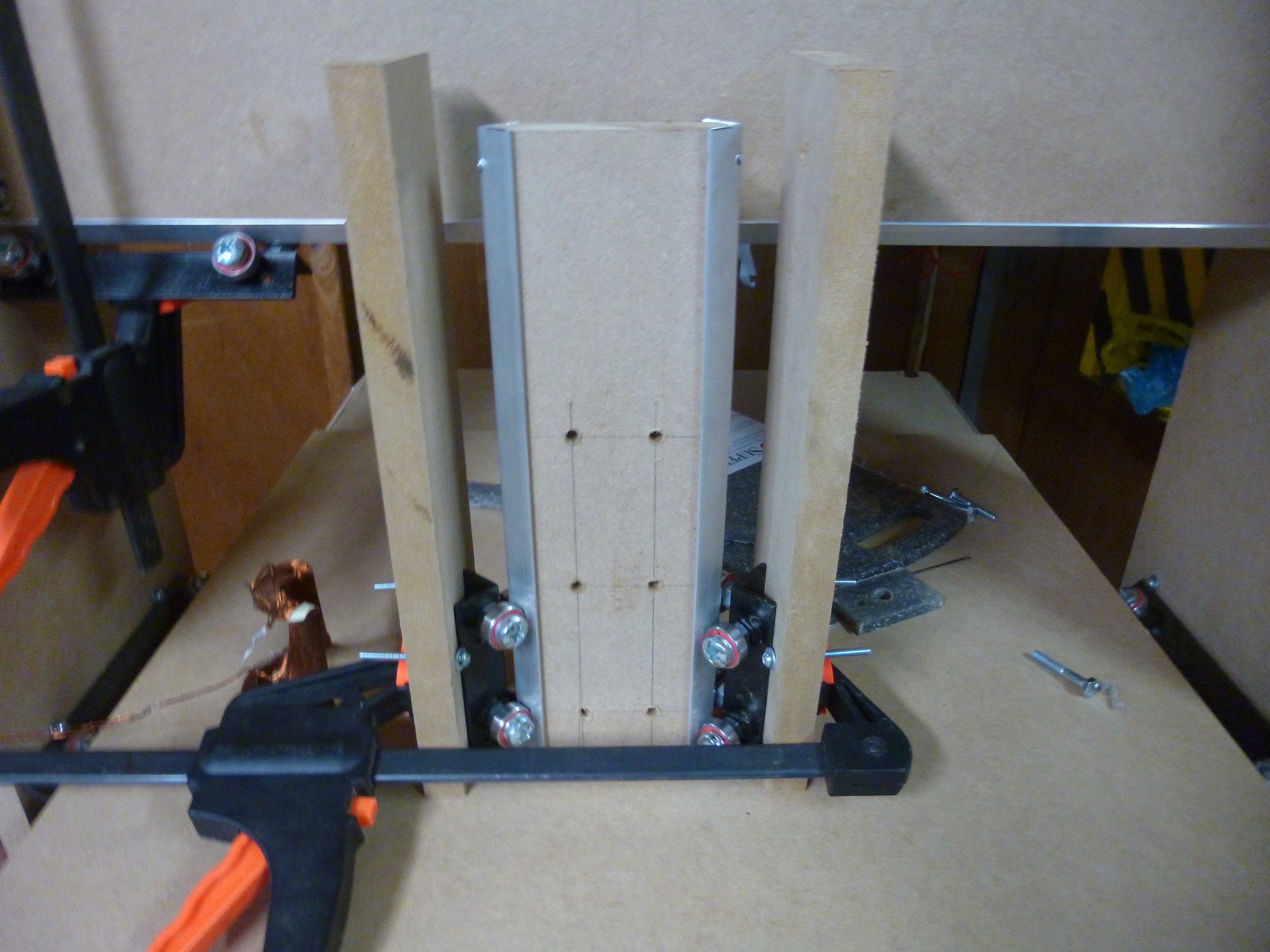
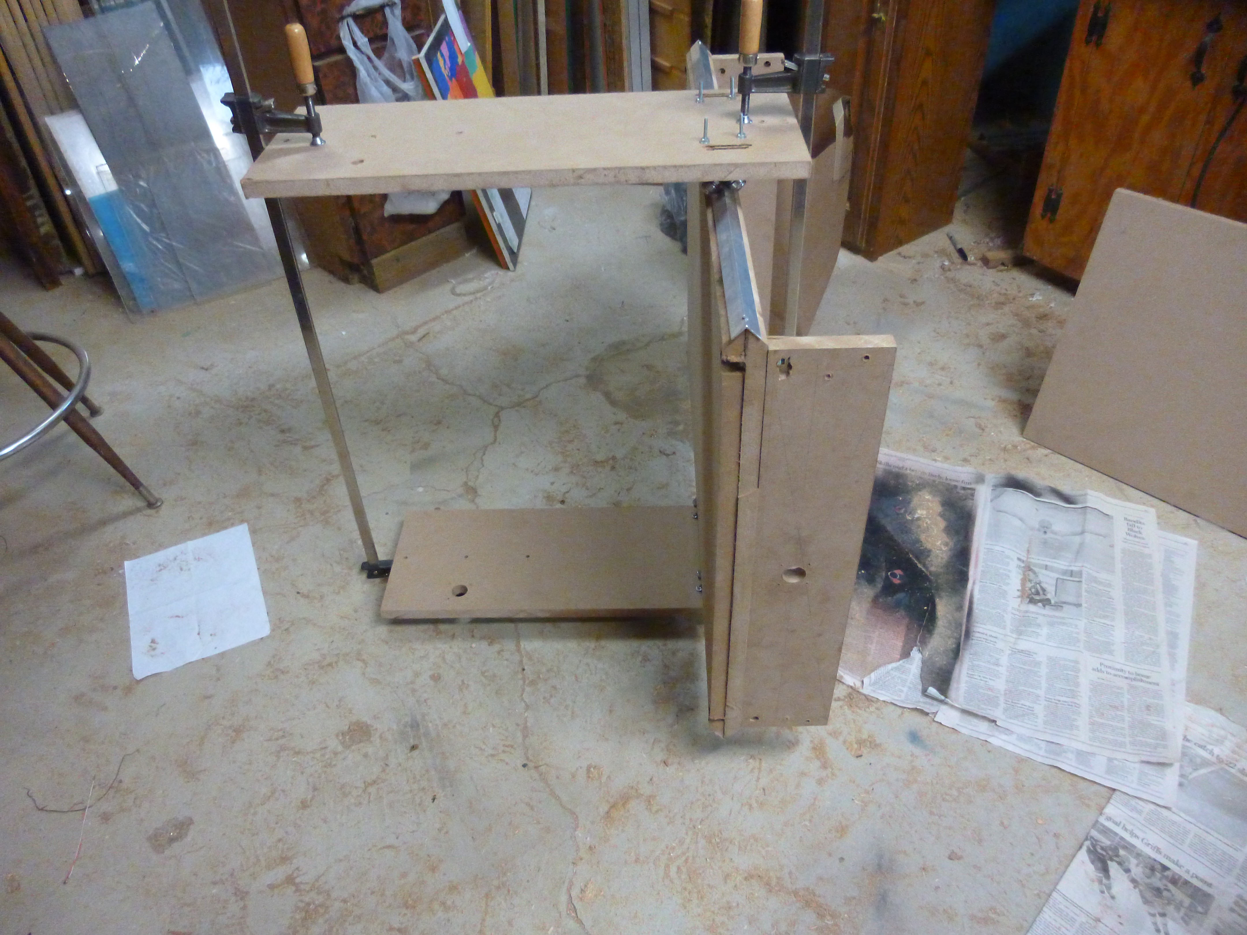
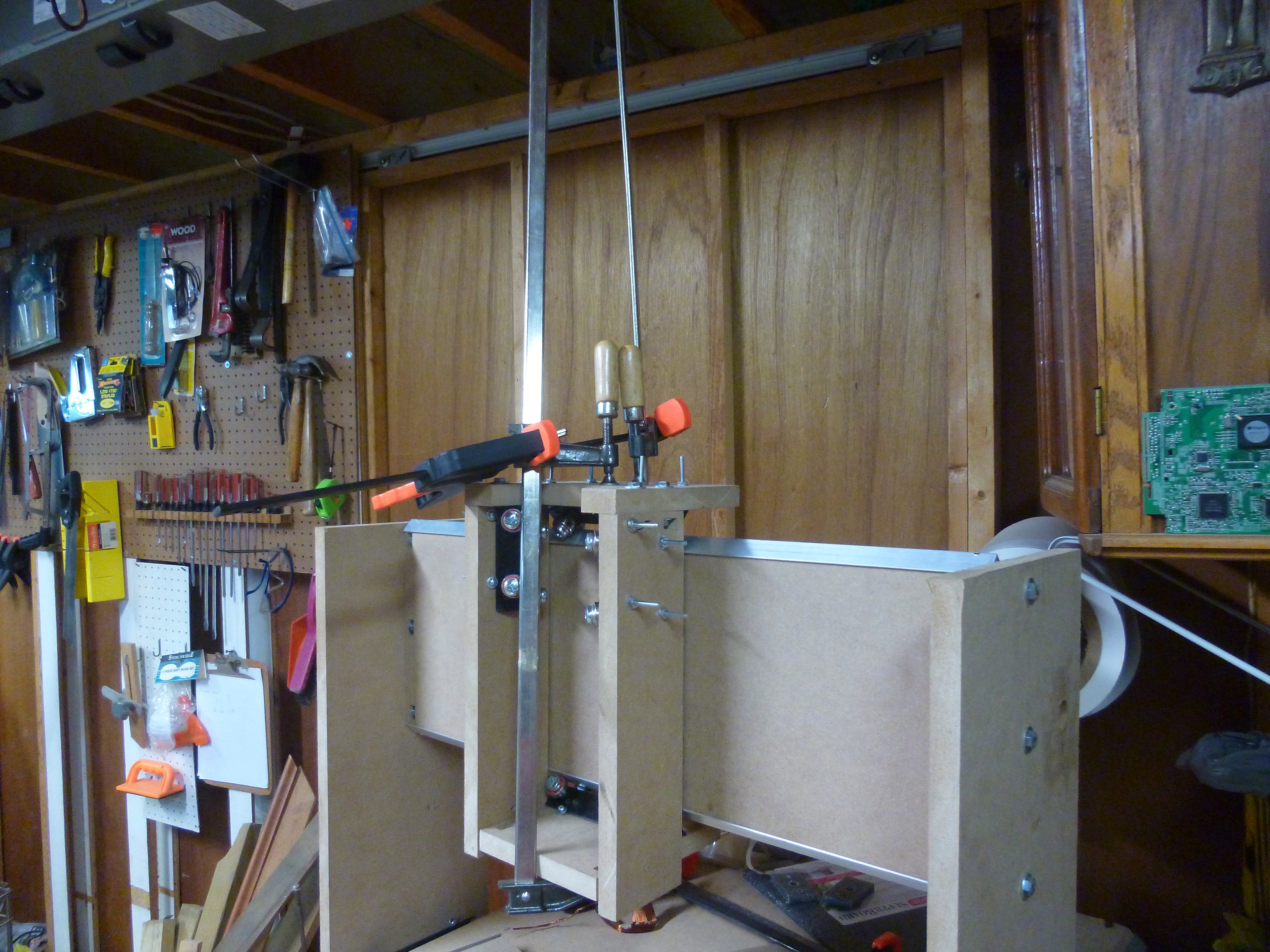 This was held in place with a couple of clamps, while I measured to make sure that it was parallel to the top plate. Once I found where it was suppose to go, I marked and drilled the holes for the top plate.
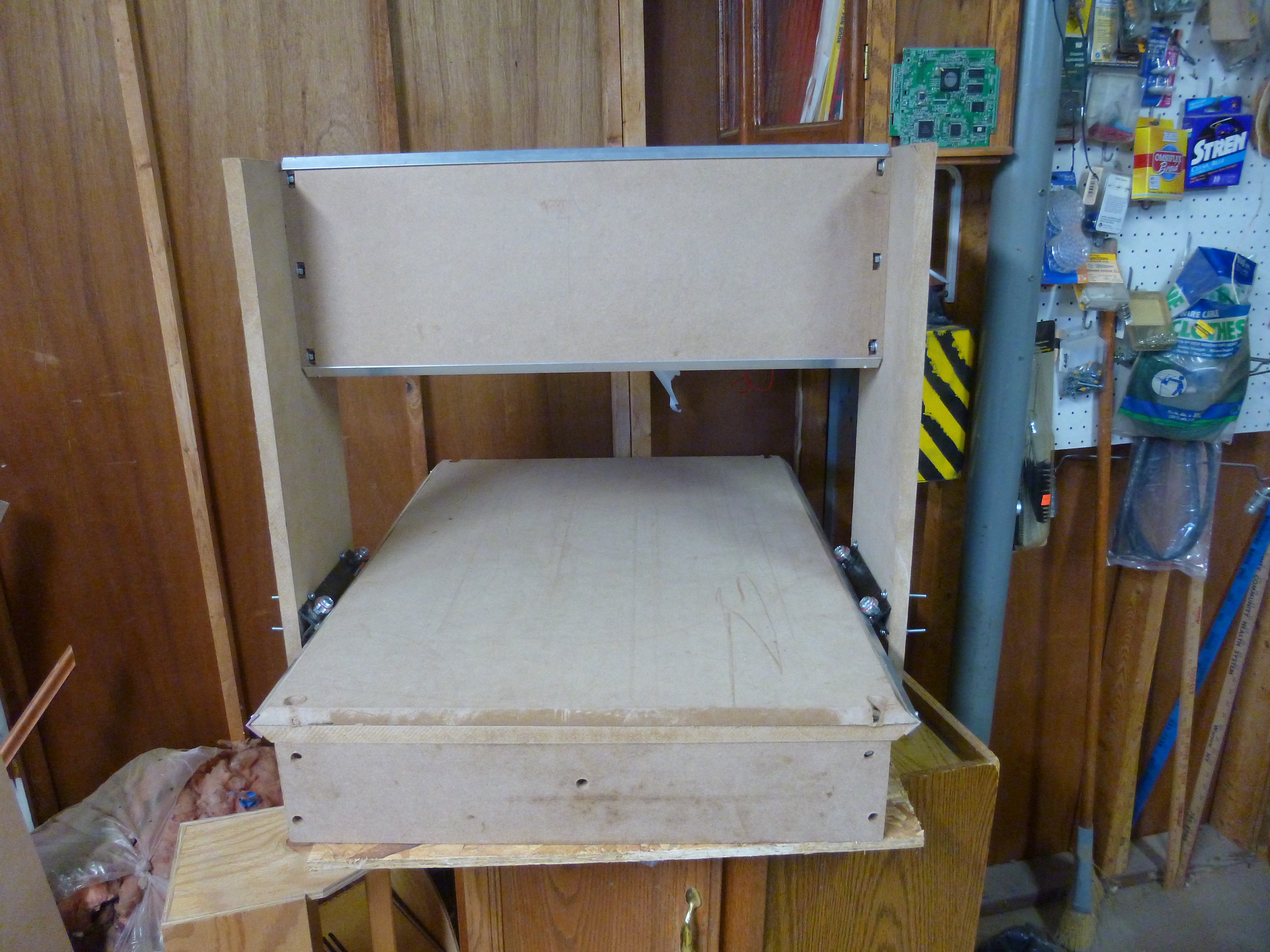
 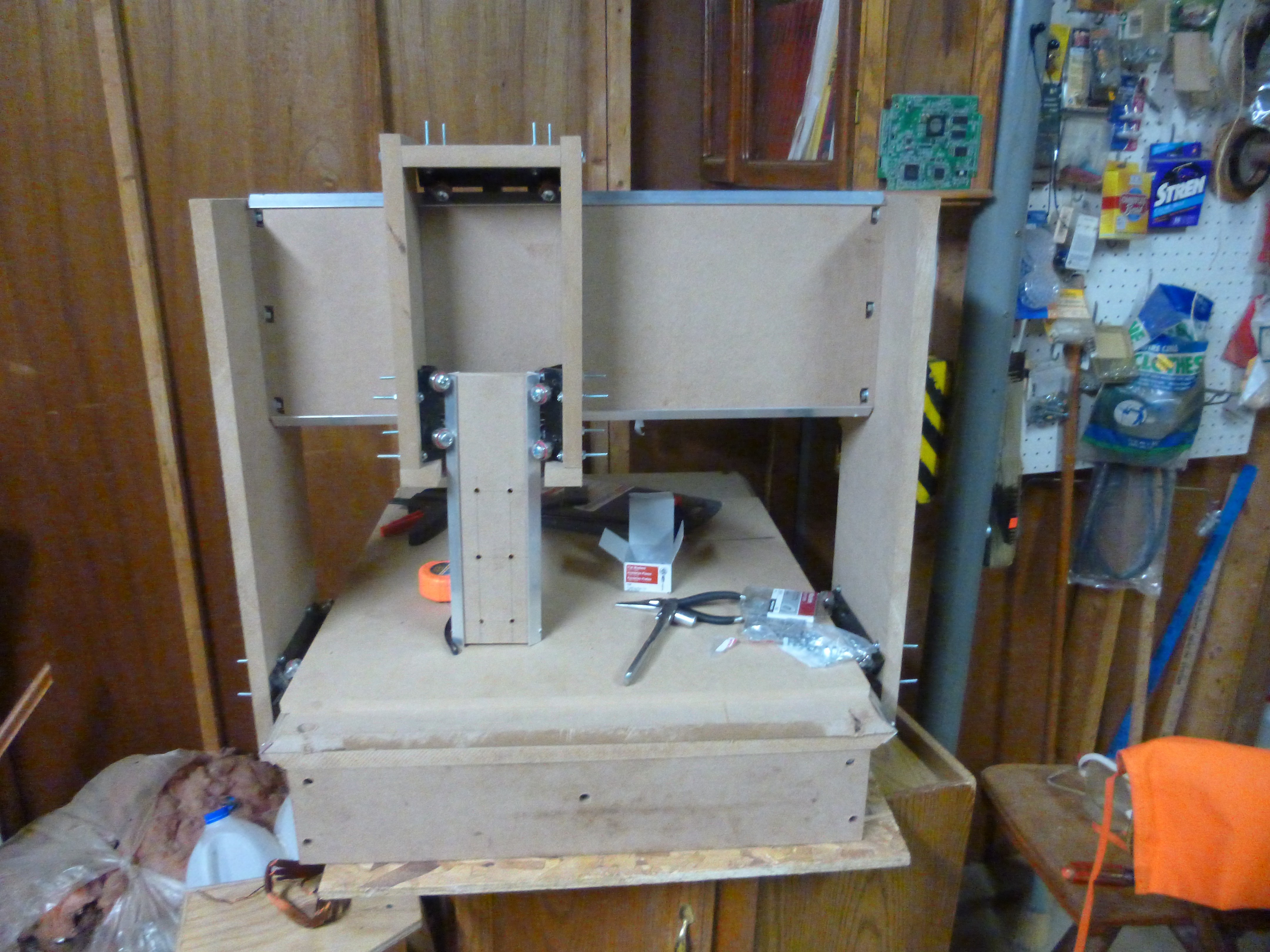 The mill is now structurally complete, however I noticed that I accidentally put the holes for the y track plate in the wrong spot on the side pieces.
 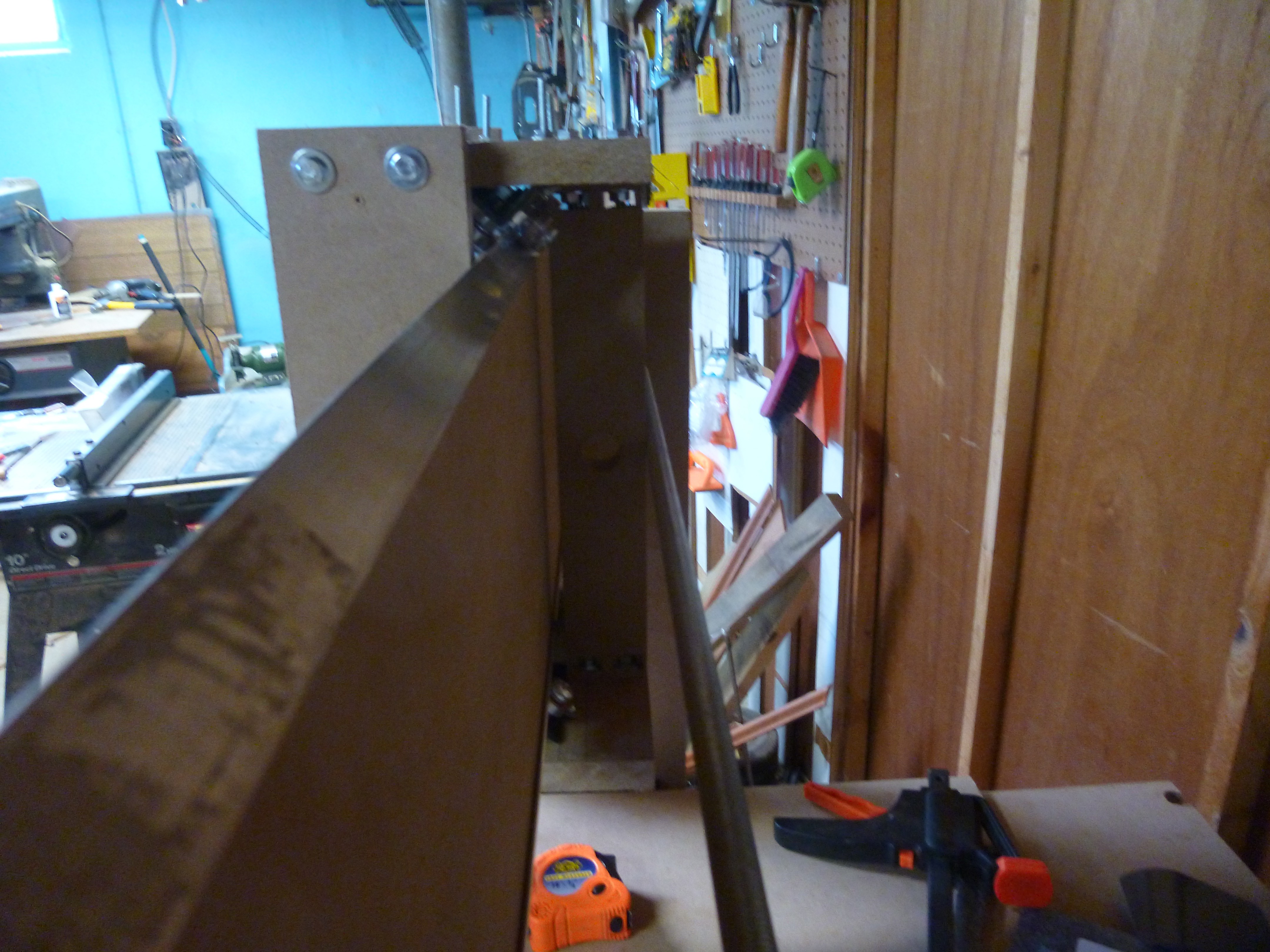 Ill (stupid sans-serif font) I will fix this when I pull apart the mill for painting.
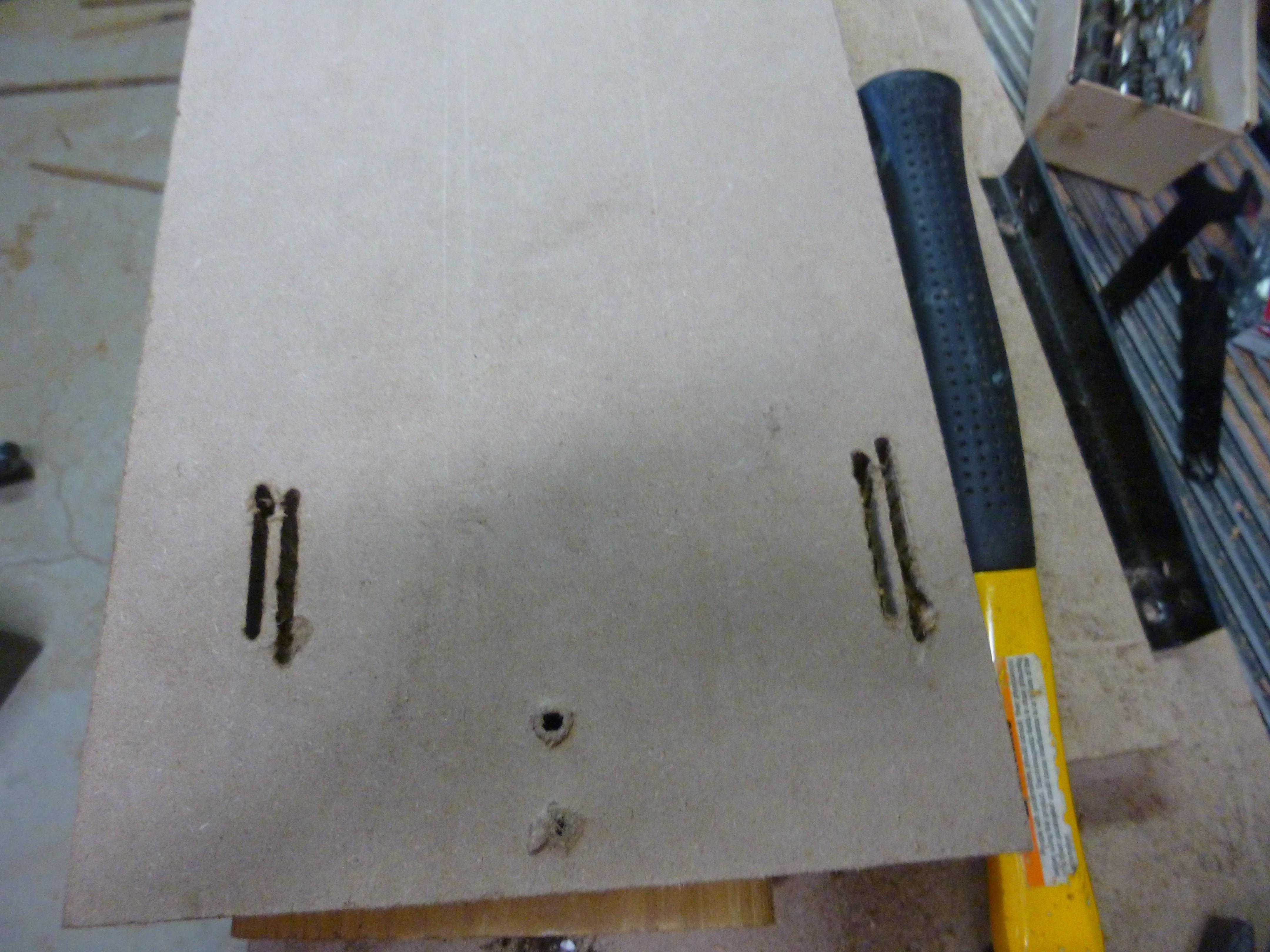
 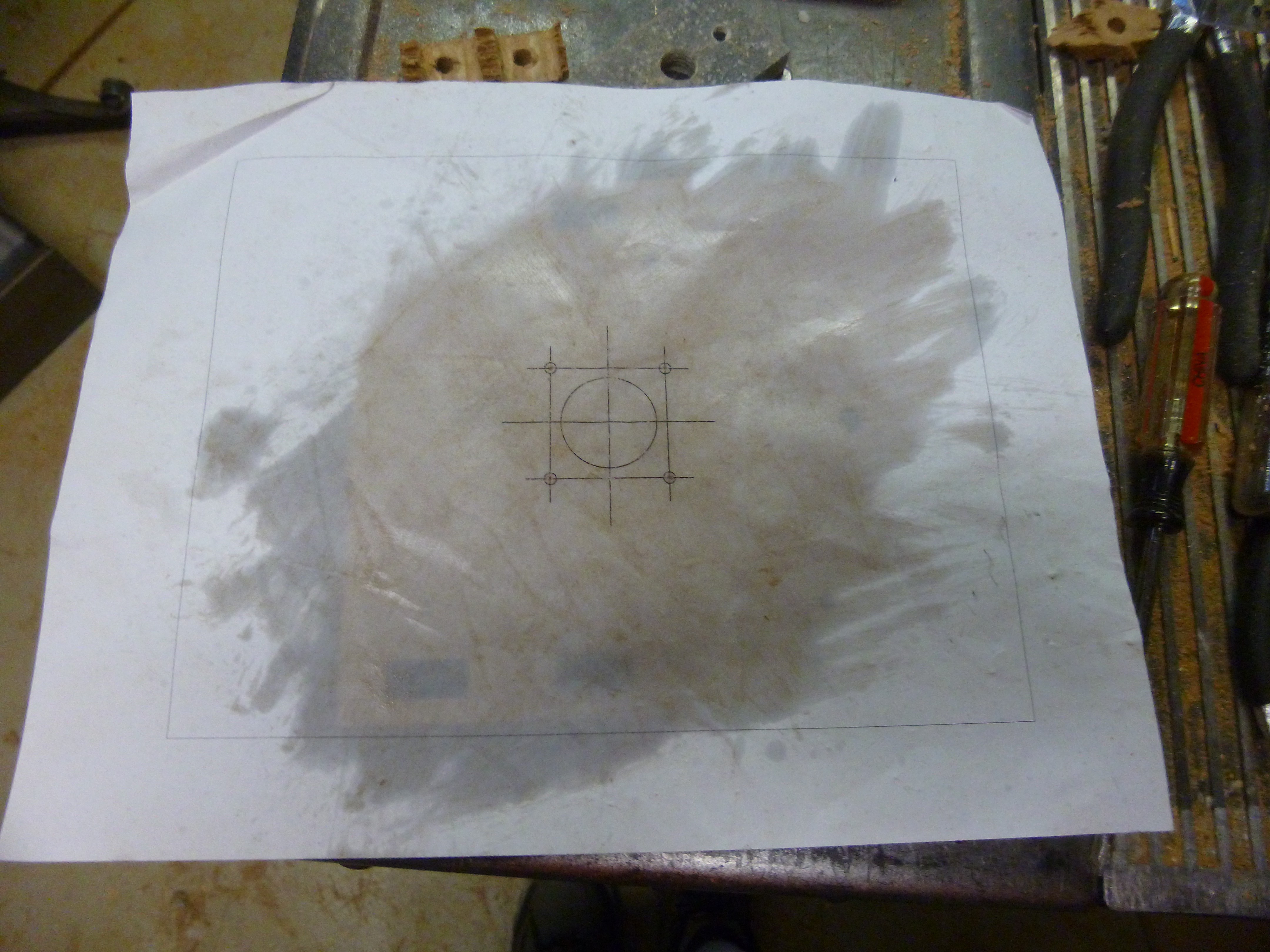 This makes the paper transparent, however it also stains the MDF.
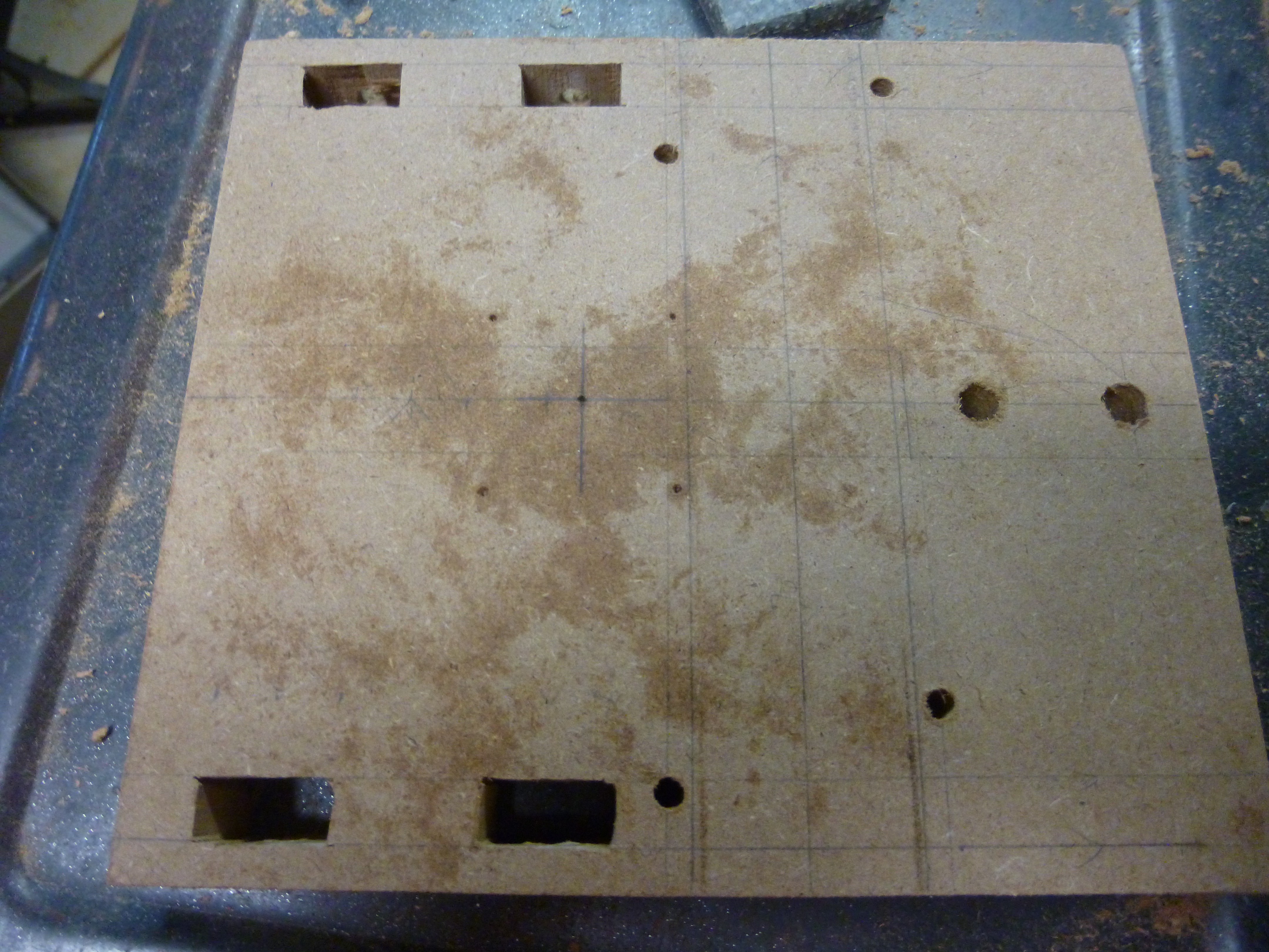
 These slots proved very time consuming to make, and didn't provide the freedom I hoped for. I was able to make the trucks fit, however I wasn't able to adjust them the way I hope.
 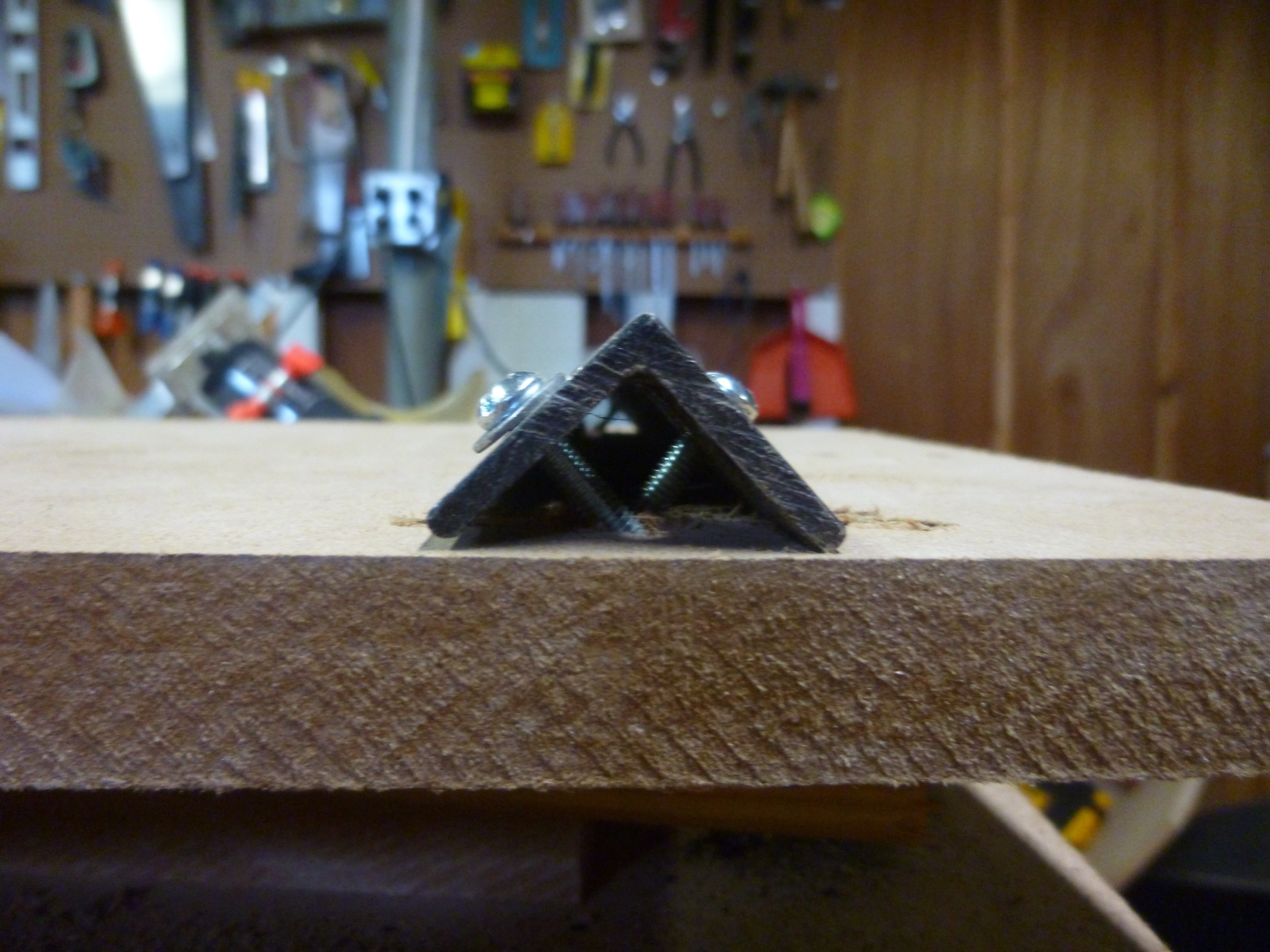 So I reverted to My original design which so far seems to be working better than I thought.
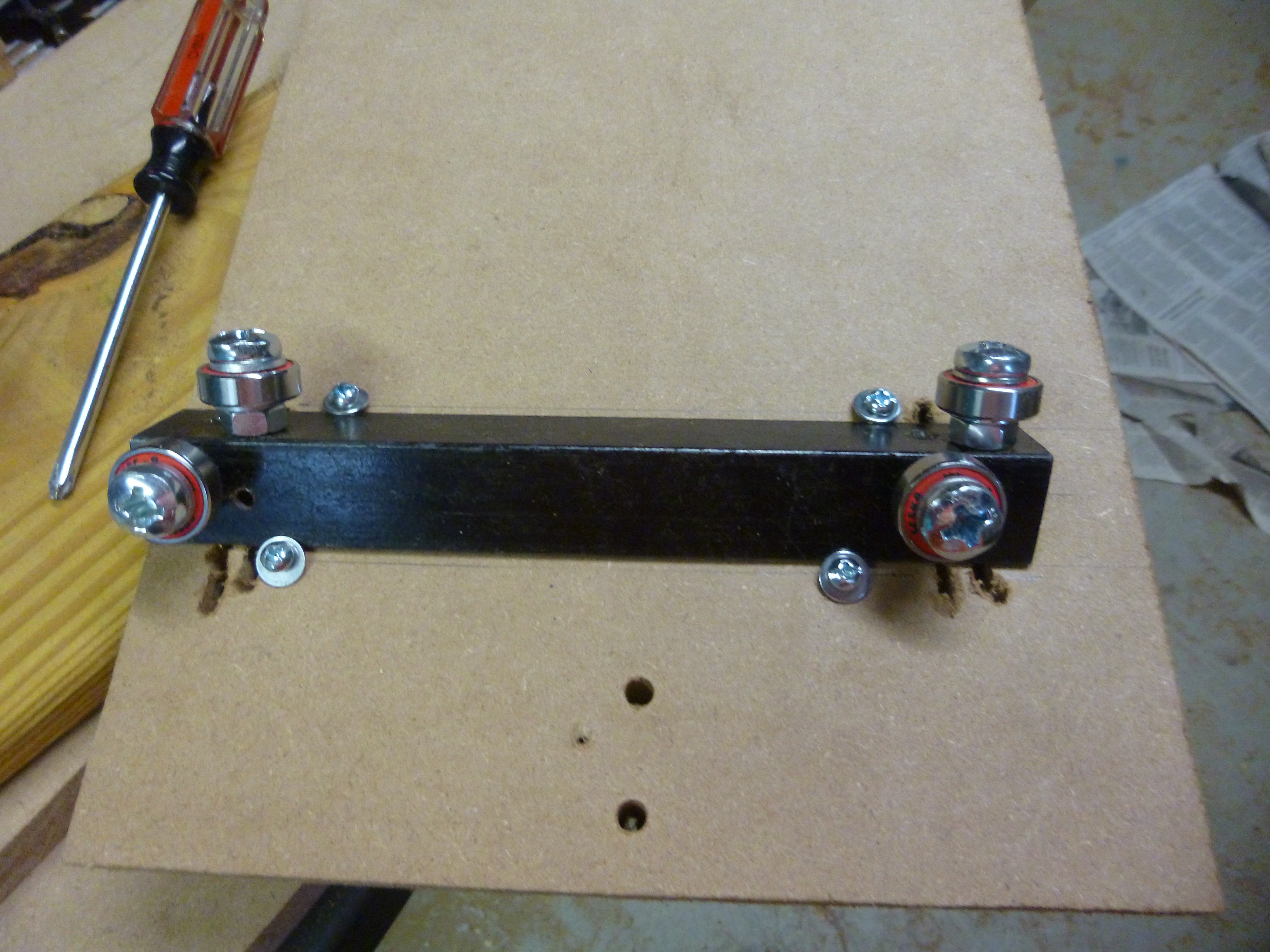
 The top and bottom pieces were cut out of more MDF, with the holes for the nuts cut out on a scroll saw.
 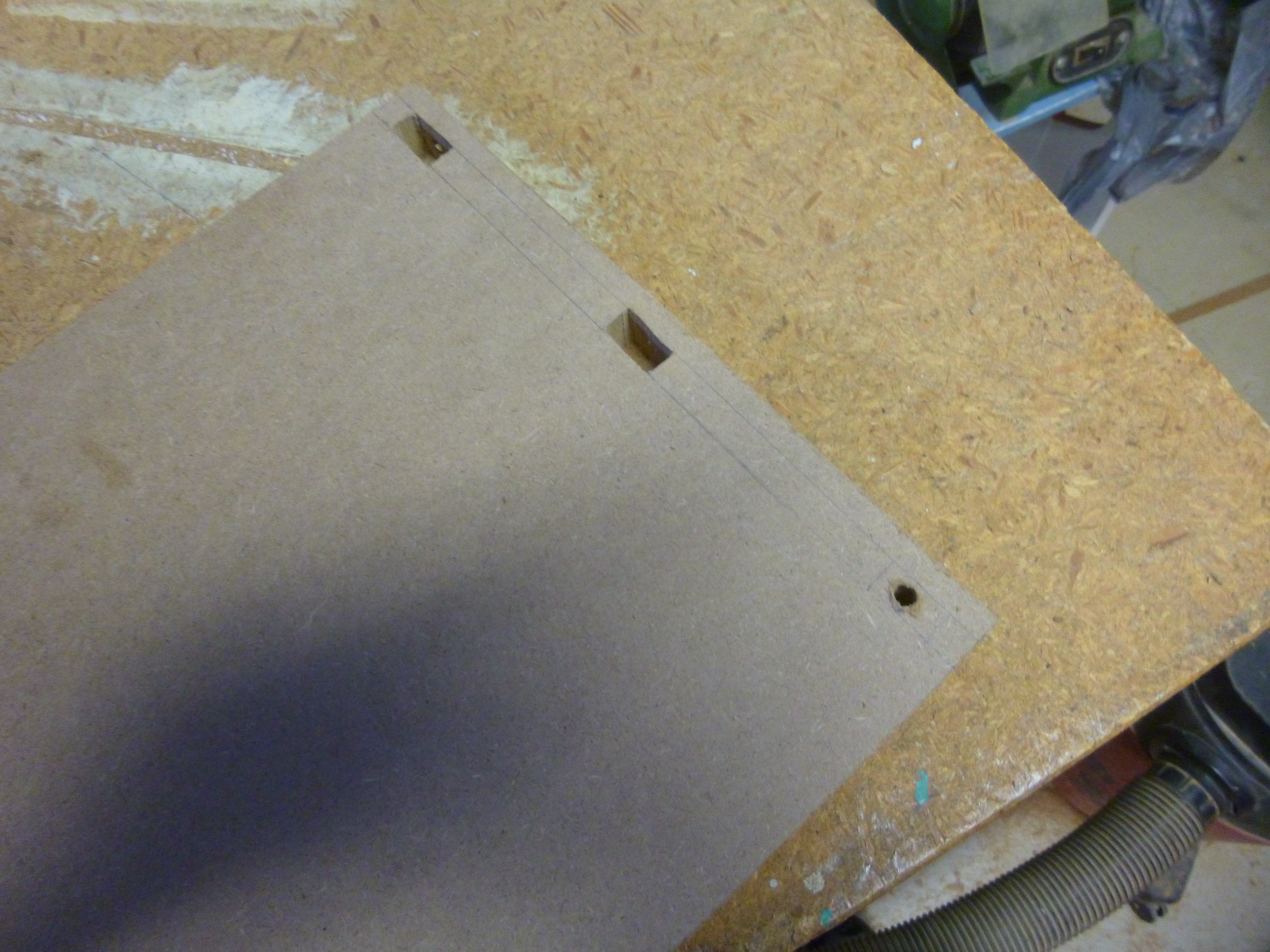 Here I have two holes cut while the third has a pilot hole drilled for the saw blade.
 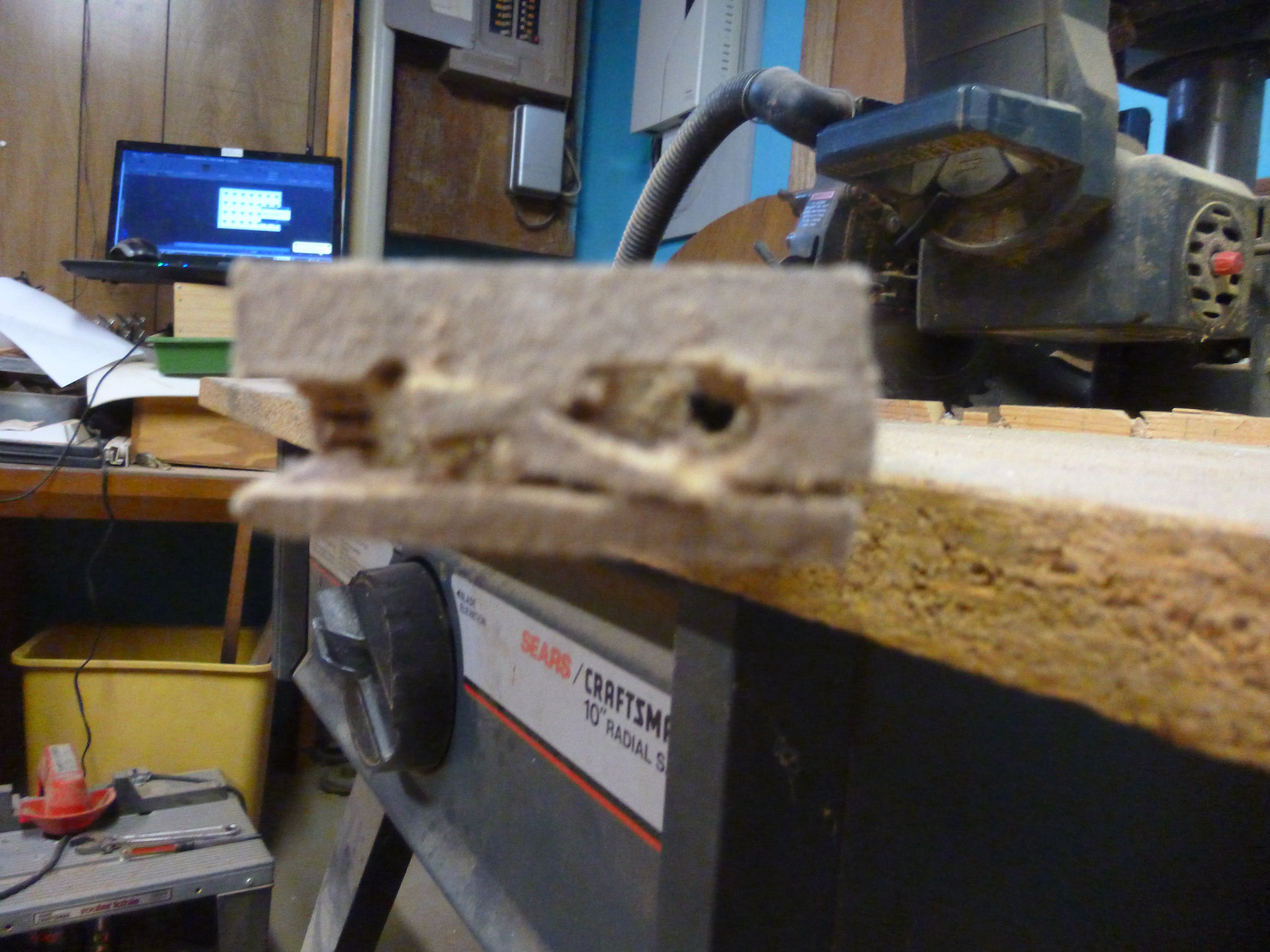 Otherwise this happens. ;-)
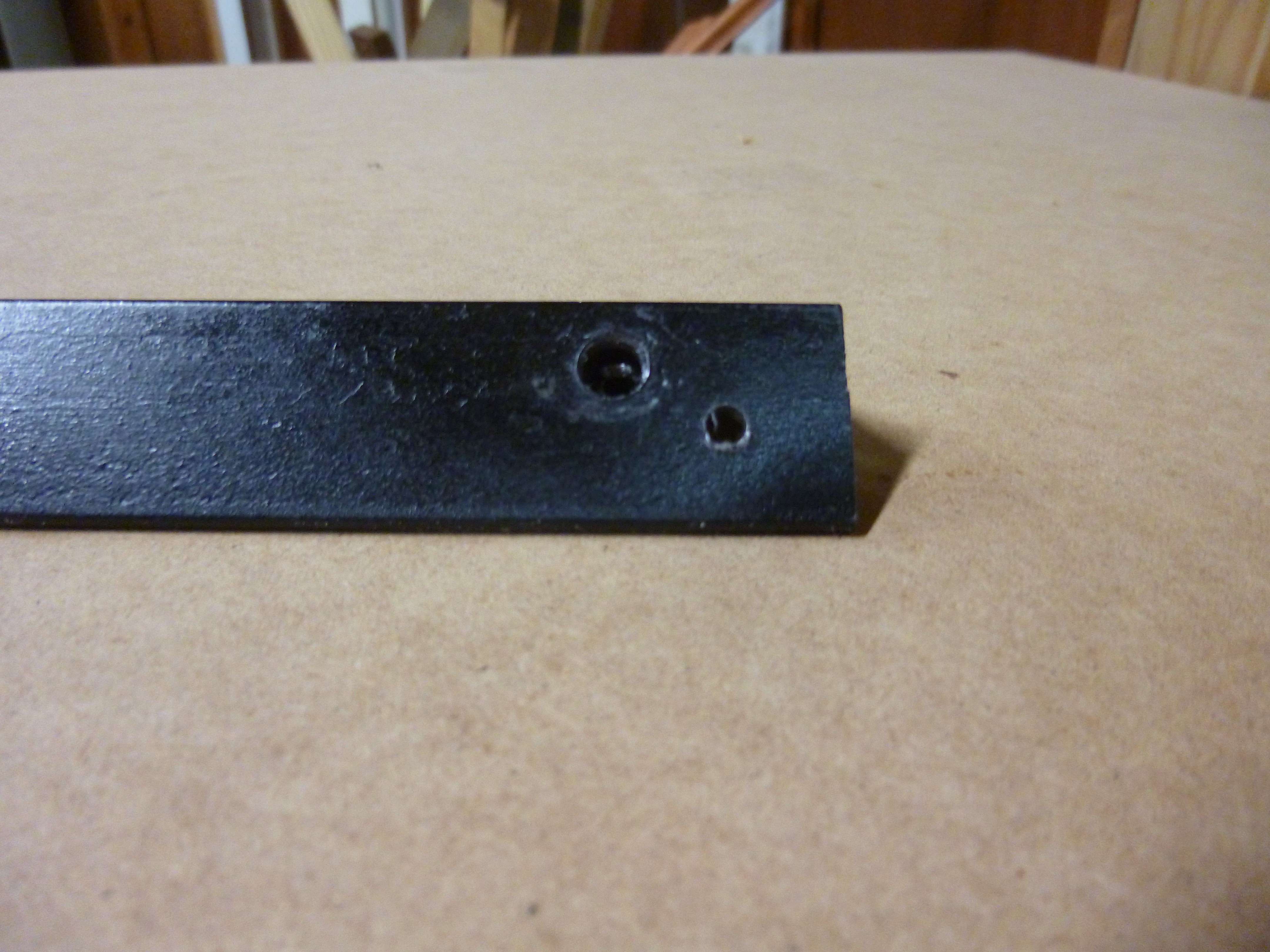
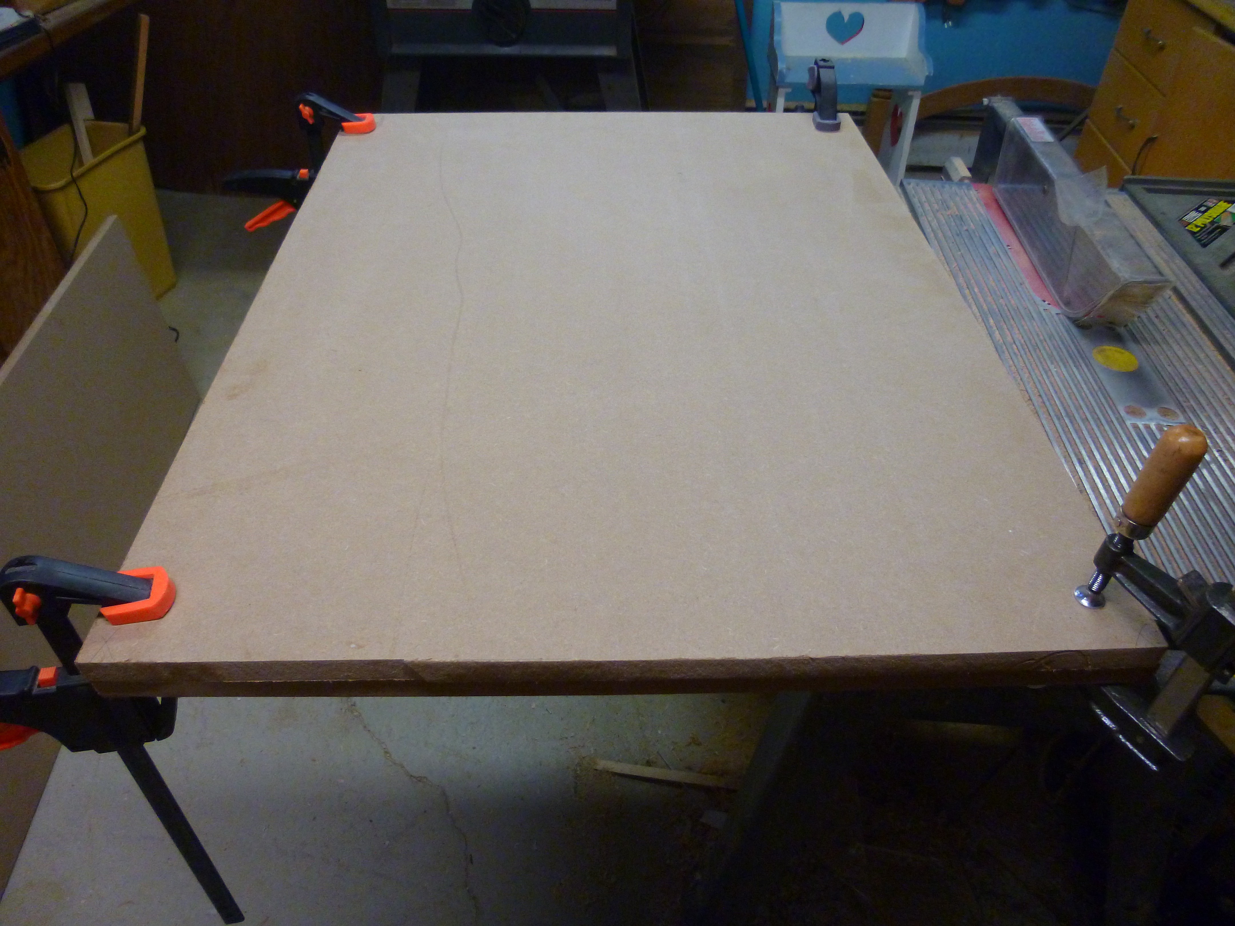 It was just after I glued the sheets together that I realized that one sheet of 3/4" MDF would probably be strong and stiff enough. After the glue dried, I used the table saw to cut a 45° chamfer on both sides of the base plank.
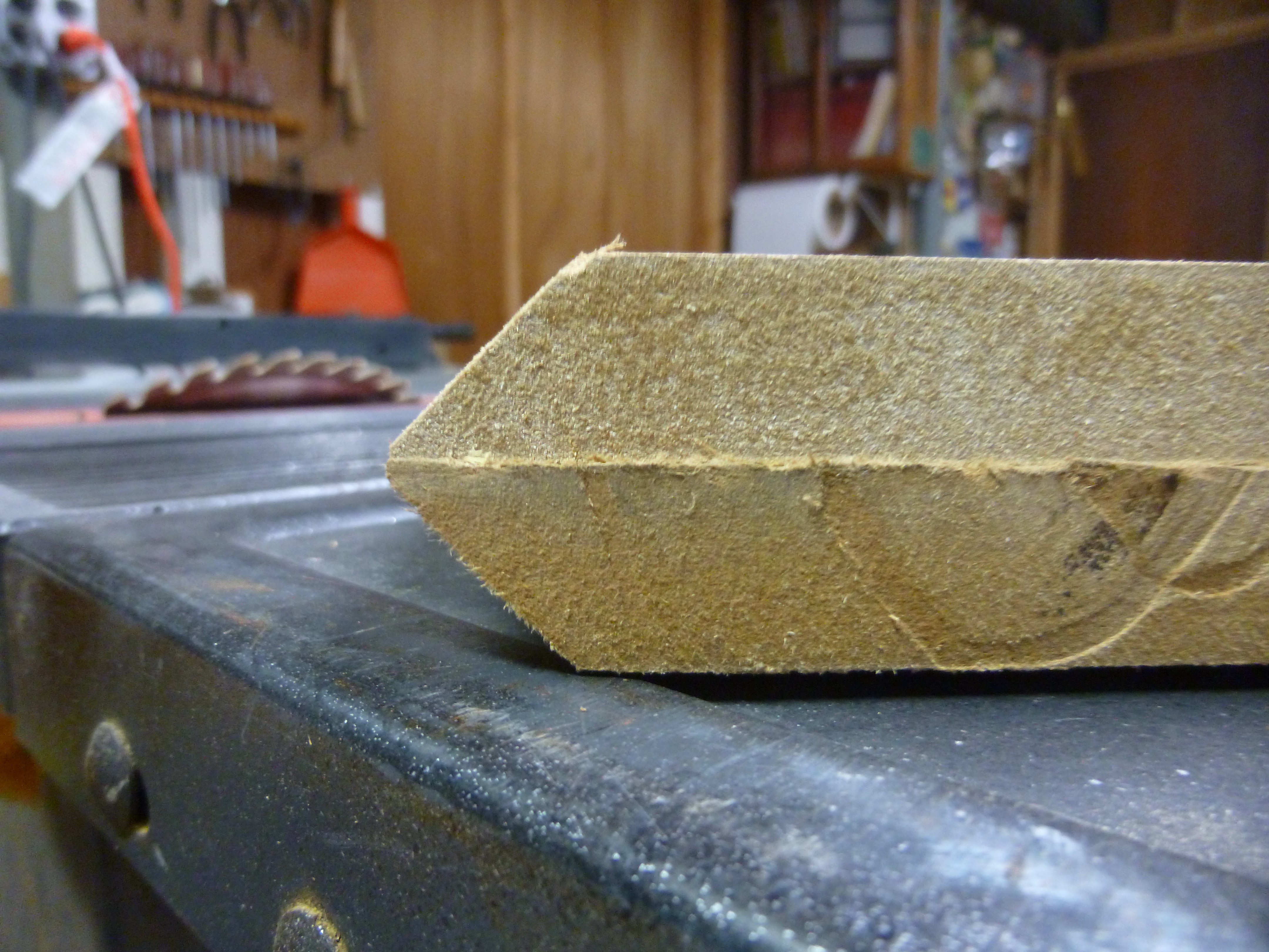
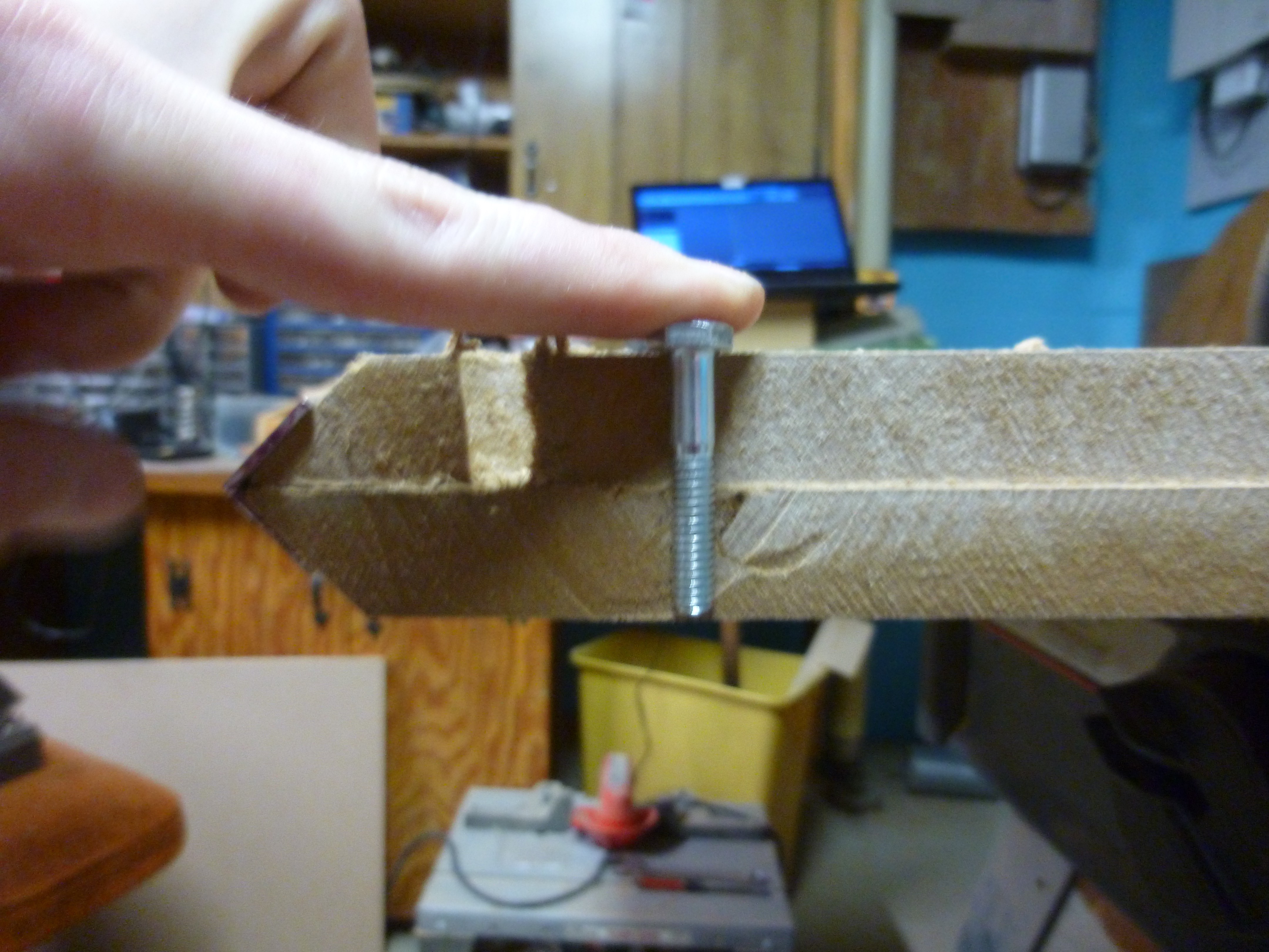 I also had to make some modifications to the holes that held the nuts
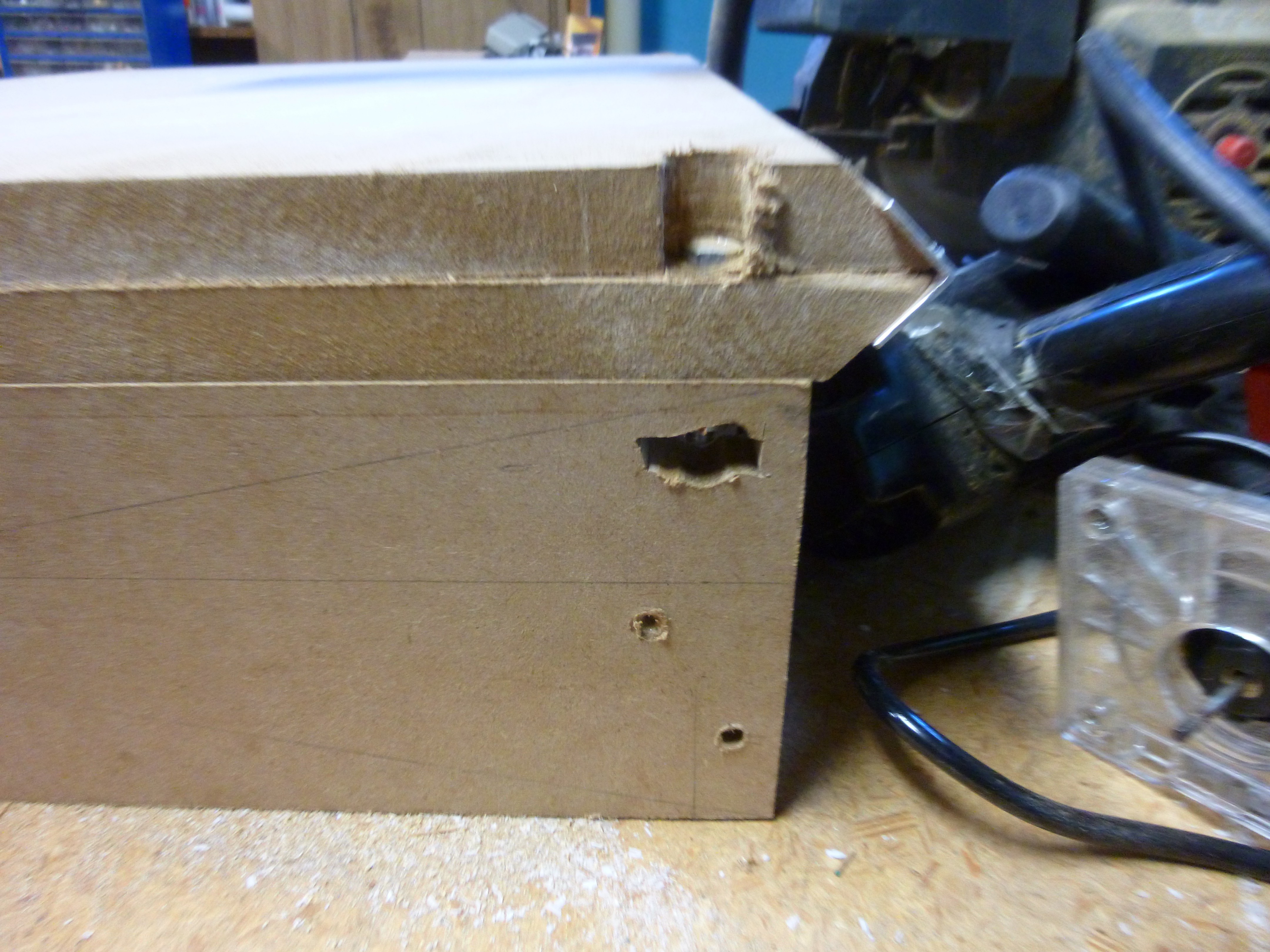 It's not pretty but it works.
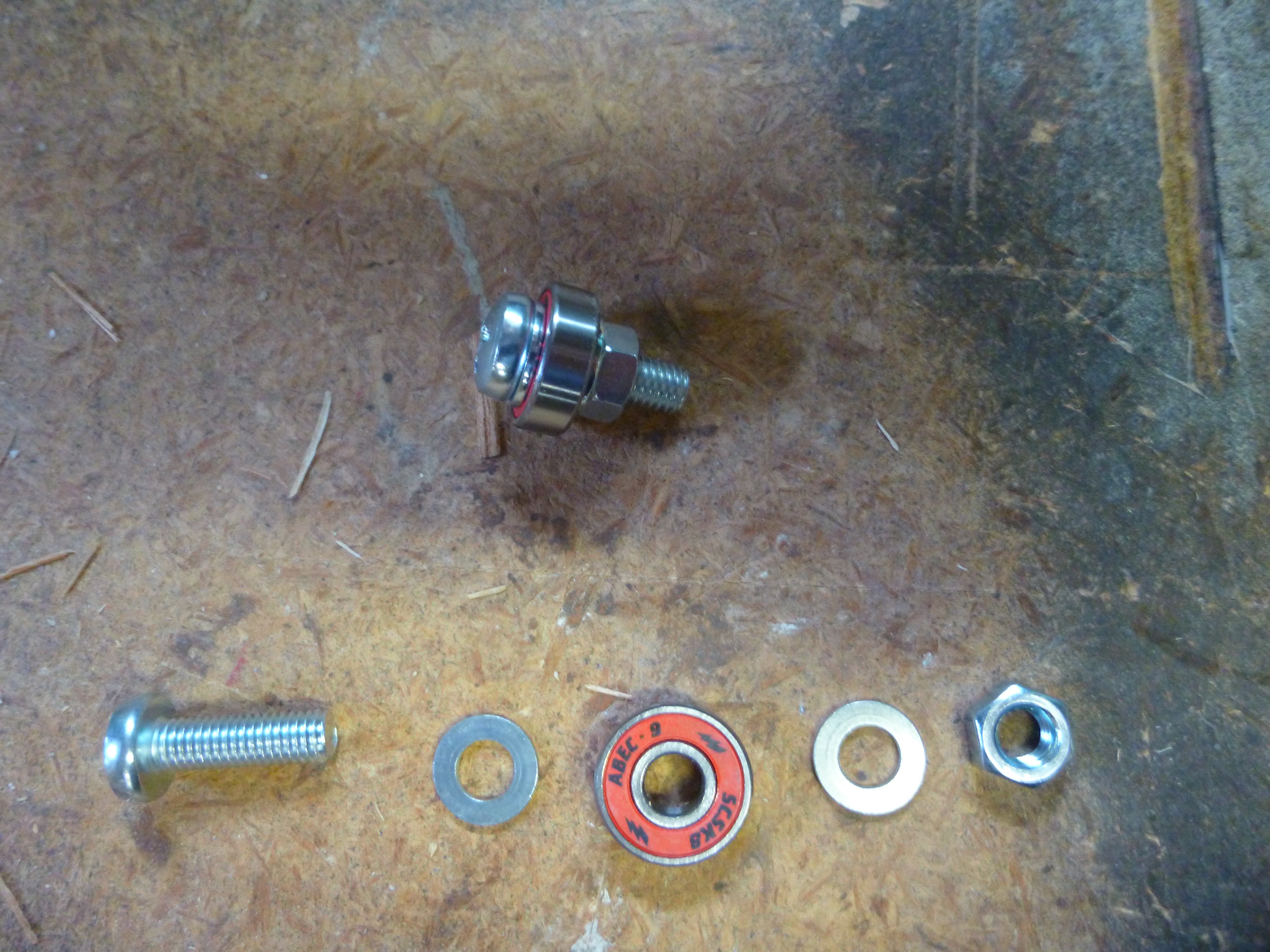
 I am not sure how well it shows in the image, but my jig is two pieces of scrap wood, nailed together, so the one forms a "wall" to set the angle against. I made a mark at 1" and 1/2", to line the angle against, and drilled away.
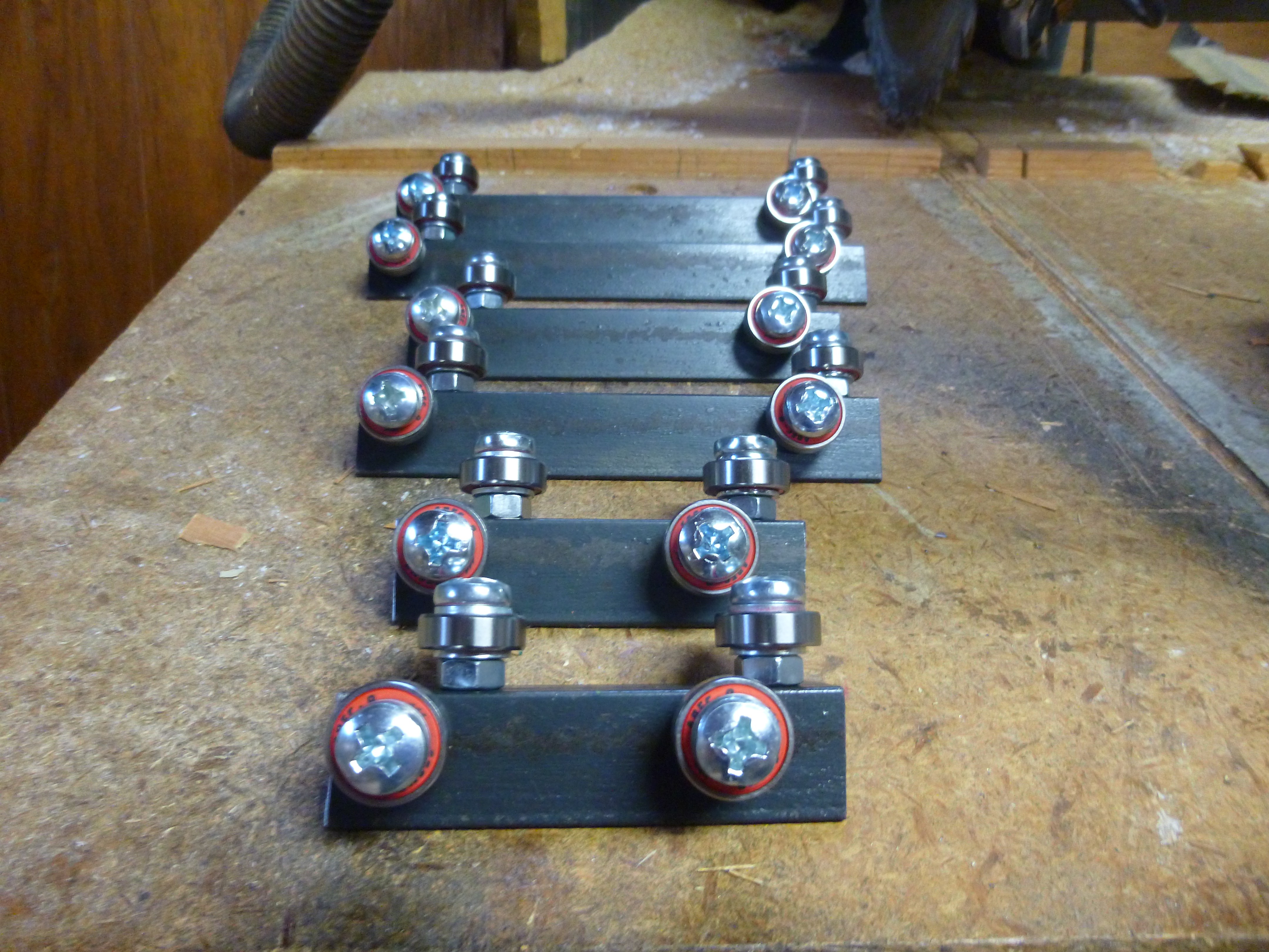 After I assembled the trucks, I realized that I should have painted them to prevent rust. So after disassembly and a quick scrub in soapy water, I gave the pieces of angle a quick coat of spray paint.
 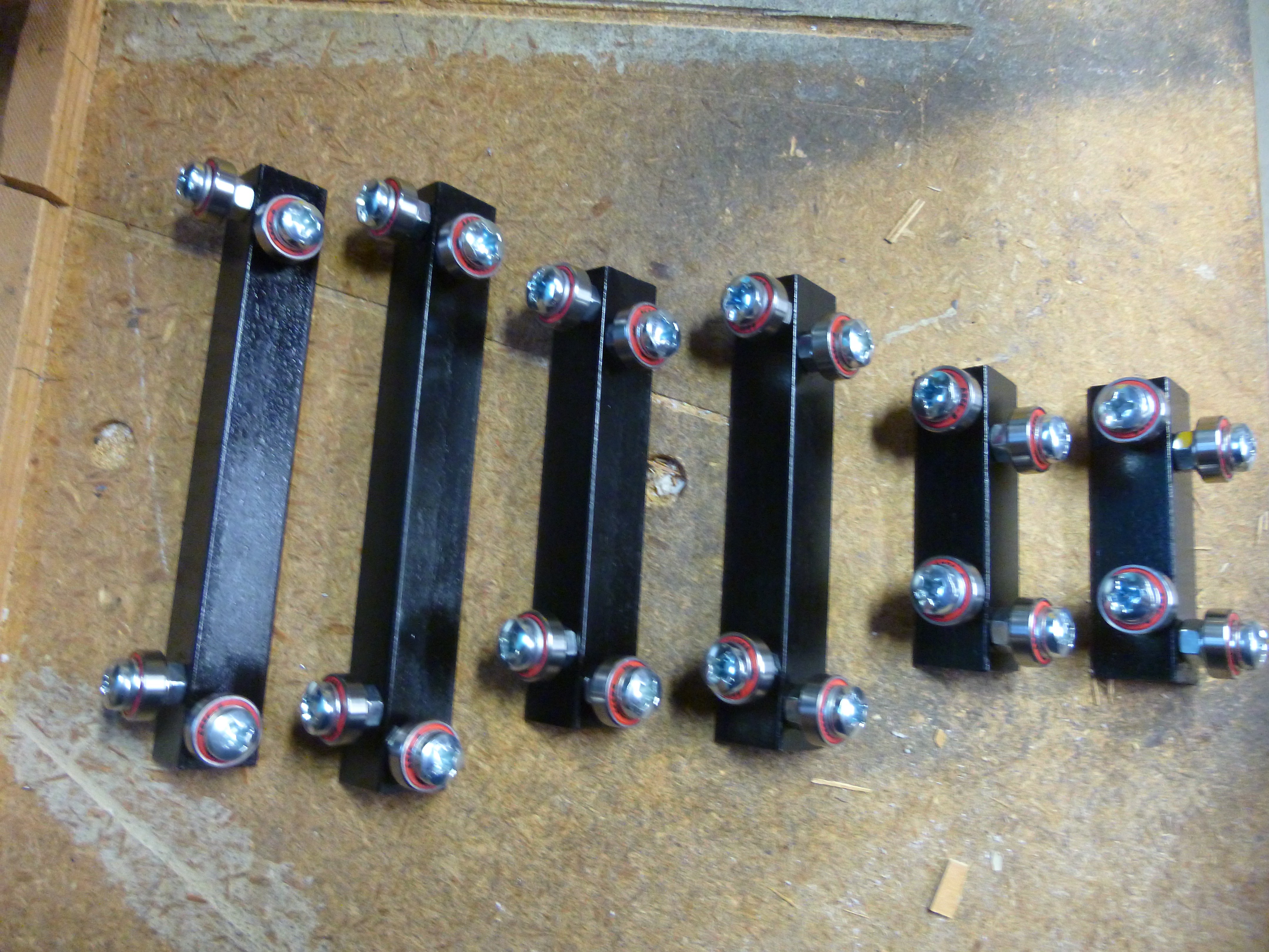 Well that is the easy part done. Next I have to build the base plate, and gantry.
 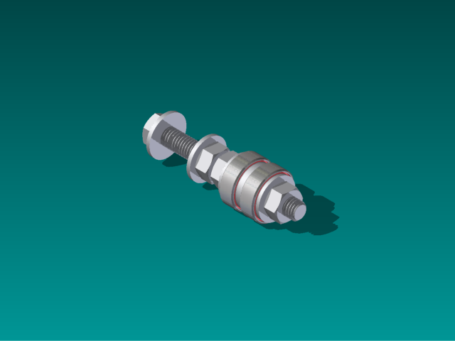 This would require twelve bearings per axis instead of the eight my final plan uses.
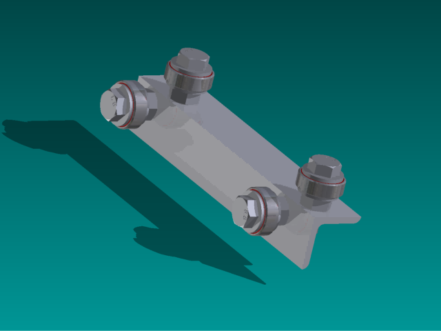
 dekutree64
 zakqwy
 BoneConstructor
 willbaden