 ziggurat29
Summary:
Coming off of yesterday's apparent success with the low-level signal stuff, I decided to start coding the decoder.
My current idea is to measure the distance from bursts, and that, combined with knowing the last bit received, will allow me to correctly decode the incoming signal into actual data values.
This worked. (And now I have an even better idea.)
Deets:
Yesterday I mentioned that I believe I should be able to decode the bit values by measuring the time between bursts, coupled with knowing what was the previous bit value. I started by making a table of the 4 scenarios, and computing the related timing value in timer ticks.
Here it is:
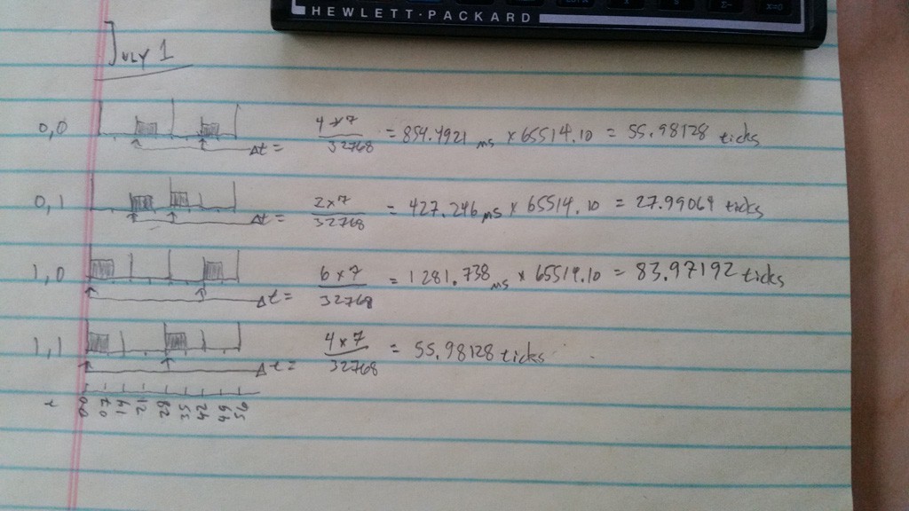
Case 0,0 and 1,1 have the same timing value, and so it is necessary to know the previous bit to disambiguate. Actually, this case is pretty easy: the current bit is whatever was the previous bit.
For the code, I implemented this as a sequence of range comparisons. This picks up faulty cases as well as the valid ones. For faulty ones, I am currently going back to the 'hunt' state, but I could conceivably do error correction using the parity bits in some cases. I'll mess with that later, though.
Because of my merged pulse work-around, the first burst may be coming in during the timer ISR (if the first bit is a '1'). I need to take that into account. Further, if the first bit is a '0', then I also need to take that into account in the EXTI ISR. I handle this situation in two ways:
- if there is a burst, then this bit is definitely a '1'. Go ahead and shift it in, and set the 'last edge time' to 0, which is what it would be if we clocked it in from a perfectly demodulated signal.
- if there is no burst, then we know the bit is a '0', but we can't shift that in yet, because later we will have a burst in the second half-bit time, which will be coming in via the EXTI handler. So, we fake the system a little, by pretending we have already received a 0-bit, and setting the 'last edge time' to -28 (where the sample would be if there really was a preceding 0 bit). Doing this makes decoding work out correctly in that case.
The rest of the signal decoding occurs in the EXTI ISR, and bits are shifted in as they come in. To handle timing variances, I am using a 1/4 half-bit time window around the ideal sample time. I implemented the logic as a series of comparisons to categorize the time into the various cases.
The code for this logic works like this:
uint16_t tNow = GetTimerCount();
uint16_t tDelta = tNow - _tLastSample;	//ain't 2's complement great?

if ( tDelta < (28-7) )
    {}	//error, too soon
else if ( tDelta < (28+7) )
    {}	//case of 0,1 or error
else if ( tDelta < (56-7) )
    {}	//error, possible noise
else if ( tDelta < (56+7) )
    {}	//case of 0,0 or 1,1 this bit is the same as what precedes it
else if ( tDelta < (84-7) )
    {}	//error, possible noise
else if ( tDelta < (84+7) )
    {}	//case of 1,0 or error
else
    {}	//missing pulses
OK, testing time! Decoding the signal is a real-time process, so breakpoints are not going to be useful. I reach for my handy debugging GPIO once again. This time I simply set the line to be whatever bit I am shifting in.
Following are a couple traces of the signal from my calculator. As per usual, the CH1 (yellow) trace is the demodulator output, and the CH2 (blue) is my debugging GPIO. When looking at this trace, realize the pulse width of the debugging data signal doesn't mean anything. Rather, it's level is meaningful at the time that the demodulated IR signal goes low. So you can think of the IR signal as a 'clock', sort of. For convenience, I have annotated the trace with the bit values being shifted in.
Trace 1:
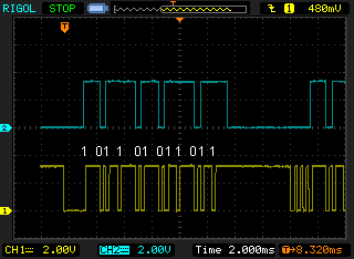
This first trace exhibits the 'merged pulse' issue -- you see the first 4 pulses are merged into one big one. The timer trick I described yesterday works around it, and also samples the first burst period, which in this case does happen to be bursting (hence the initial '1'). When the end-of-frame timer expires, I return the GPIO to 0 so it is easy to see when the next transmission comes in. This transmission decodes to:
1011 0101 1011
The first 4 bits are parity, and I won't discuss that in detail here other than to say that the 4 parity bits are individually computed over a distinct subset of the data bits, and are set to create even parity. The next 8 bits are data. So this value is 0x5b, which is the code for the '[' character.
Trace 2:
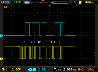
In this second transmission, the Vishay device demodulated ideally, and you can see the three start bursts the first data burst distinctly, without merging. But it doesn't matter because the workaround works the same for all those cases. This transmission decodes to:
1011 0100 0101
This is for 0x45, which is the 'E' character.
These characters '[E' are indeed what is expected, because I am testing using the 'print stack' function, and the message being sent is '[Empty Stack]'.
So, that's pretty good; I think I am decoding correctly.
Now, I will implement the parity check. Later, I will try my hand at error correction. But this will require more handling in the last 'else' case shown above. In fact, there are windows all the way out to 686 ticks, and it will get messy. But this gave me an idea.
So, my new new idea is to implement all the bit times as window cases, and not do this delta time stuff. This will make my ladder of comparisons quite a bit longer, but there are a deterministic number of windows, so I don't think it will be too bad, just not particularly pretty code (I could do something fancy with a table of window values and an advancing index, taking advantage of the fact that time moves only forward, but I'll save that as an optimization). The upside of this approach is that it will be very easy to recover from missing pulses, and also know exactly which pulses are missing/damaged to facilitate the error correction. But again, that is for later, since I've got so many more core features to implement now.
Next:
My Blue Pill board should arrive this week sometime; when it does I'll need to setup for that new board (should be quick). In advance of that, I am going to implement the parity check function, and I need to make some sort of circular buffer to which the incoming data gets pushed.
Also, since I ultimately will need to implement the serial port, I could go ahead and do that now. Doing so will give me another debug output, because I'll be able to dump all the decoded data to a terminal window. Also, I'd like to put on a couple blinkenlights to indicate 'data', 'bad data', etc. Then I can easily do some tests of range and bulk data transmission by visually verifying that all the data was received correctly.
Discussions
Become a Hackaday.io Member
Create an account to leave a comment. Already have an account? Log In.