 kodera2t
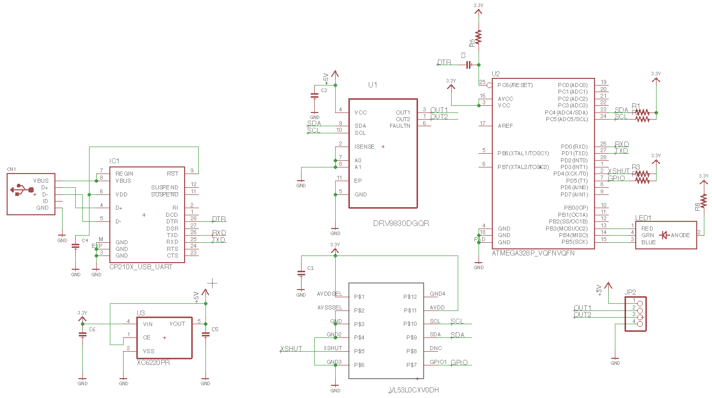
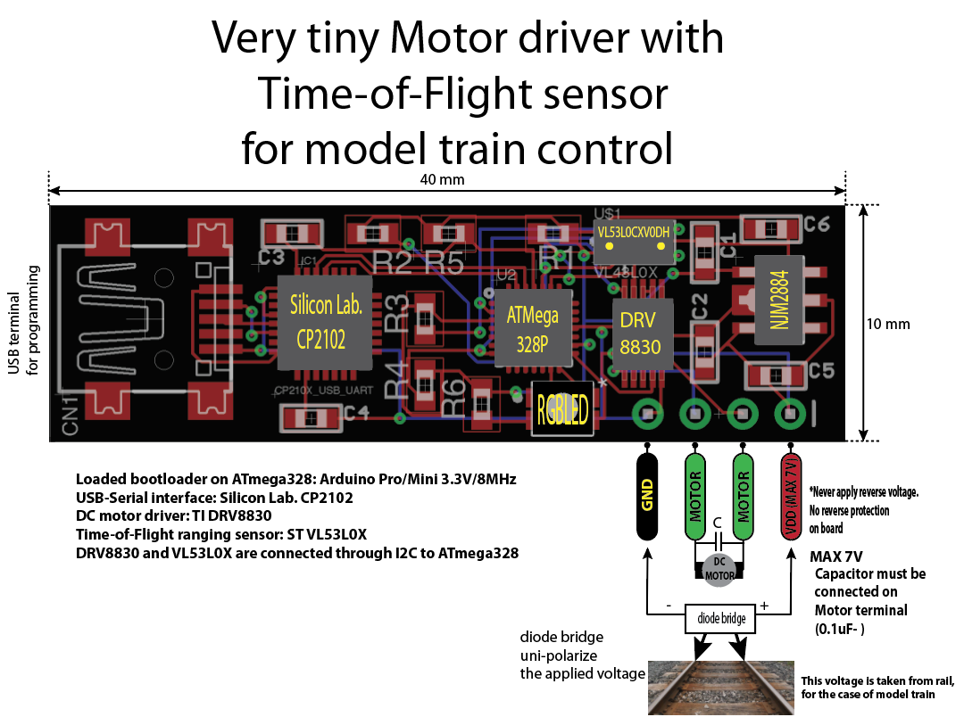
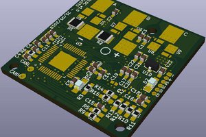
The above picture shows the whole schematic contains CP2102, ATMega, ToF sensor, motor driver DRV8830 and 3.3 V LDO. ToF sensor and DRV8830 are connected through I2C bus. For ease of use, Arduino bootloader is burned to ATmega328. RGBLED is connected to PB3(D11), PB4(D12), and PB5(D13) for operation indicator.
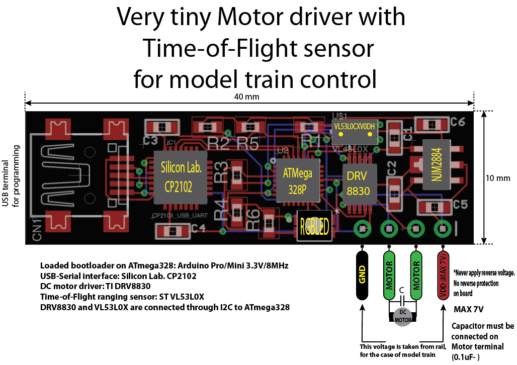
This is the pinout of the board. This board has just 4-terminals, VDD, GND and two motor terminals. CP2102 is USB-bus powered and not powered for standalone operation. VDD can be applied from "rail" of model train but maximum applicable voltage is 7V (not 12V). Generally max rating of N-gauge train is 12V and this means we can not enjoy "full-speed" operation but full-speed by 12 V will be around 5-600 km/h scale speed (1/150) and, I guess, 7 V operation is enough for most of the case. This maximum is limited by DRV 8830's max rating. One capacitor (around 0.1 uF to 1 uF) must be added to motor terminal as close as possible to motor, in order to avoid noise interference from motor to ATmega.
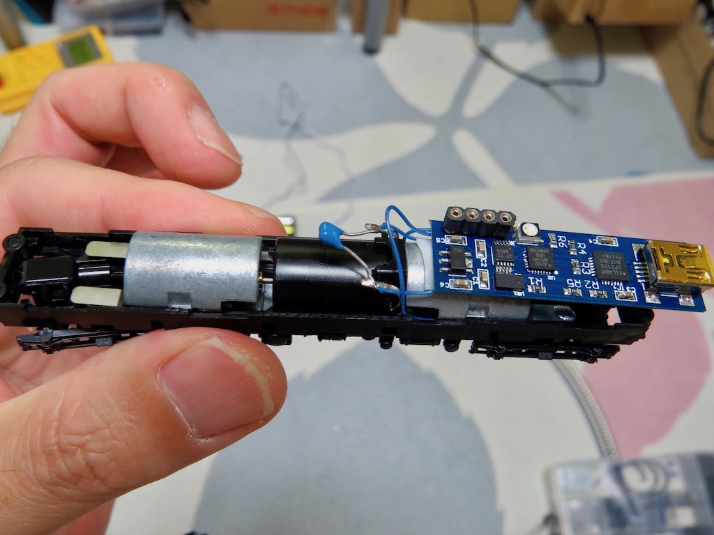
This is a "temporary shape" of the model train, without covering body. ToF sensor emit Infra-Red Laser beam and receive from object and will need to make two small holes on the top roof of train body. The large blue capacitor is the "noise killer" of DC motor.
The actual operation can be found in the following movie (indeed software is still premature..)
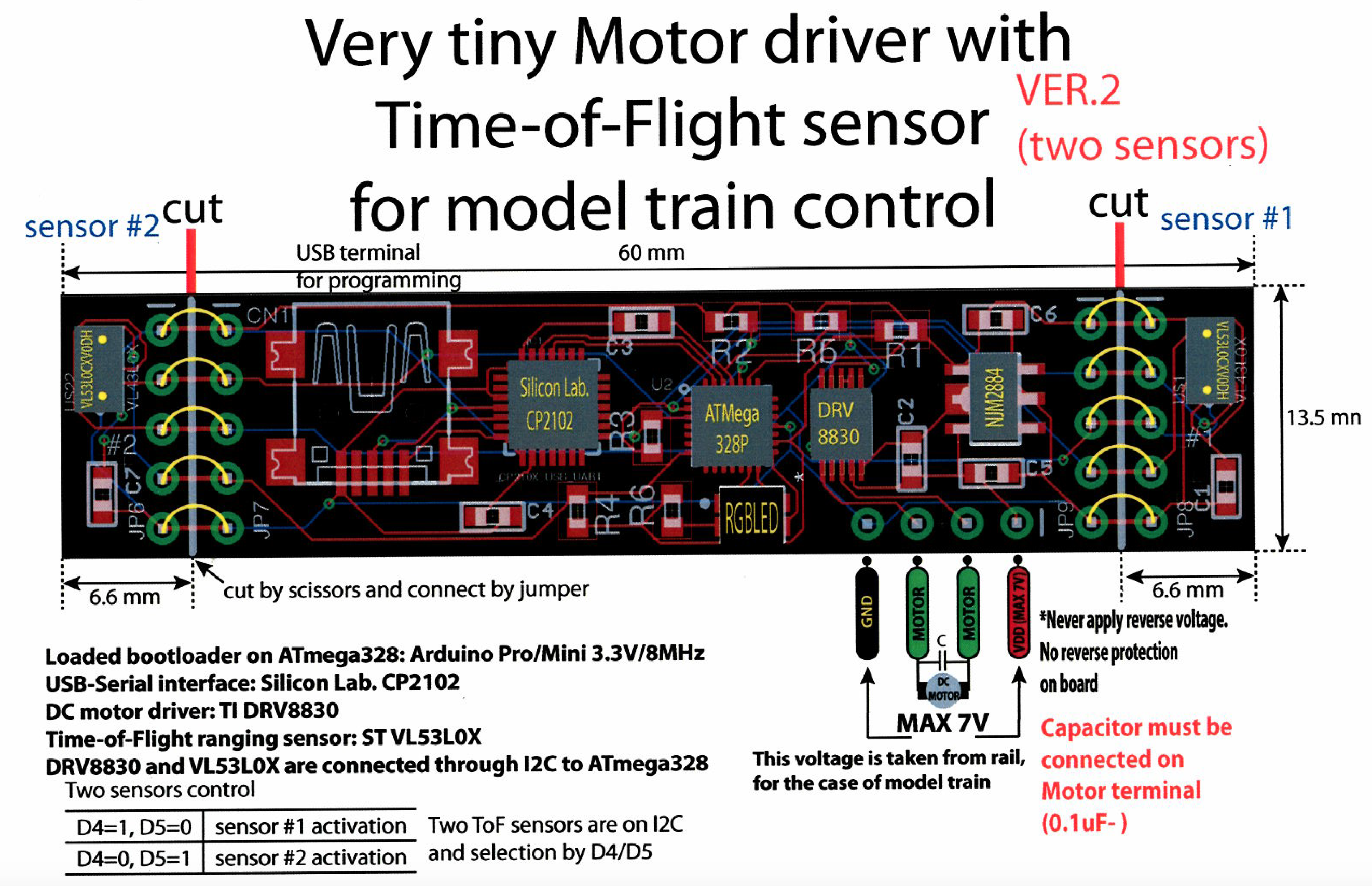
And now it will have revision #2, with two sensors!


 Ruediger F. Loeckenhoff
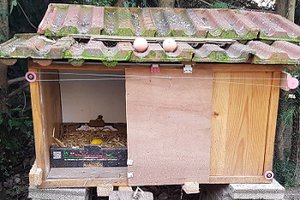
 Alberto
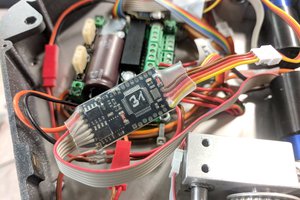
 Salah Missri
Oh... thank you for very nice information!!