 Maarten Janssen
Let's start taking apart the VideoWRITER and see what boards we will find. I won't go into too much detail on the boards in this log, just a quick first look at them.
After removing the cover let's start by discharging the CRT. It probably holds little to no charge since it's been switched off for a while, but I'd rather be safe than sorry. I have my trusty screwdriver connected to a length of thick wire and an alligator clip at the other end for this job. I connect the aligator clip to some of the metal frame and squeeze the screwdriver under the anode cup of the CRT. No clicks or pops from this one that suggest a charge, but I always repeat this process at least ones after a minute or so just to be safe.

Power Supply
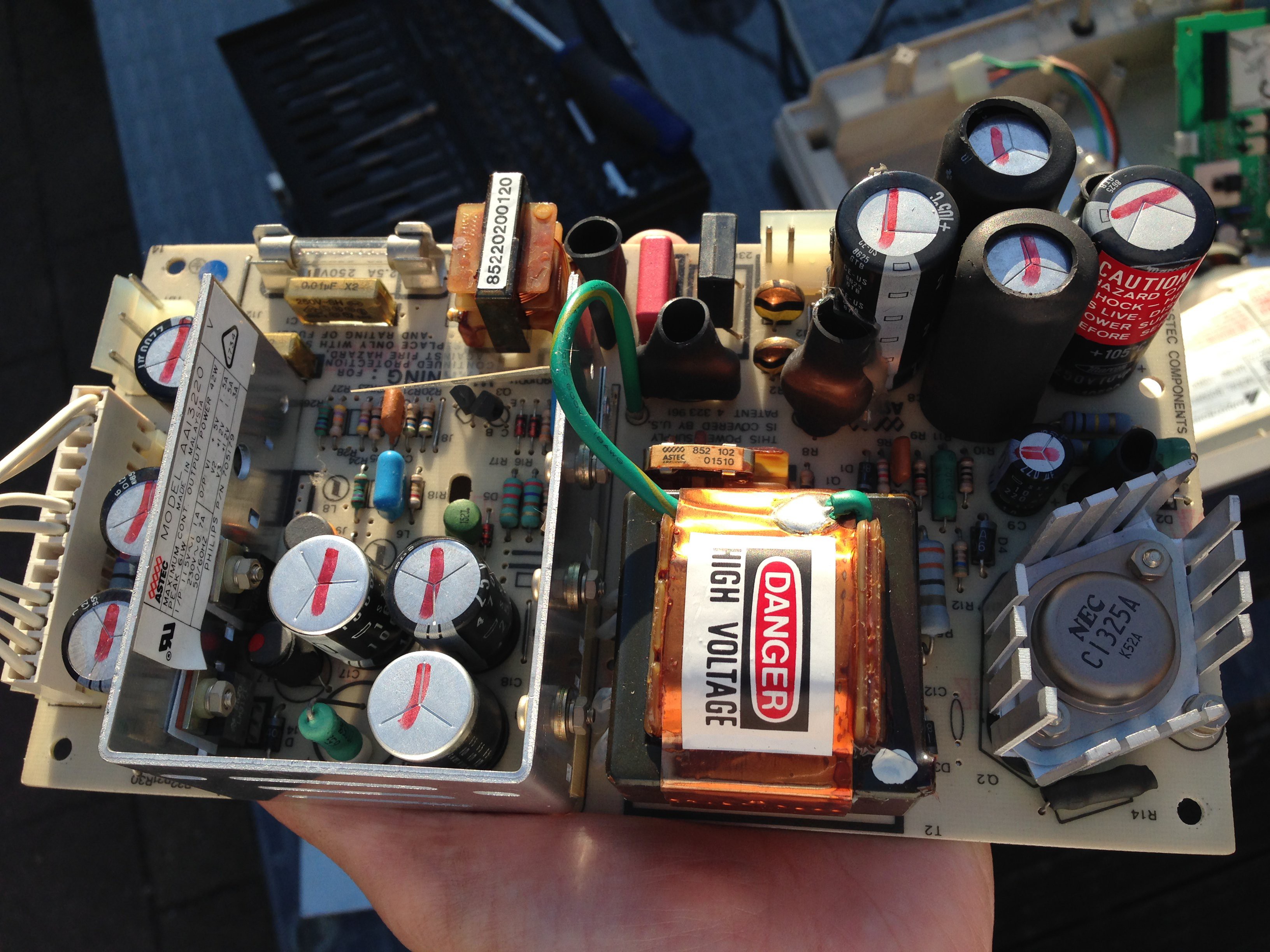
Ok now we can safely start touching things and taking the boards out. First up is the power supply. Just two screws to remove here and the PCB comes out. I should mention that this is the second time that I remove the power supply. When I was testing the VideoWRITER a couple of weeks ago before putting it up for sale one of the caps violently exploded. There was a lot of smoke and that special smell of burnt electronics. Luckily I had a spare cap in my parts bin so I was able to replace it (it's the red cap in the top middle of the board). The power supply was working again, but whether there are still other problems with this board that caused the cap to blow is still a mystery.
Monitor Chassis
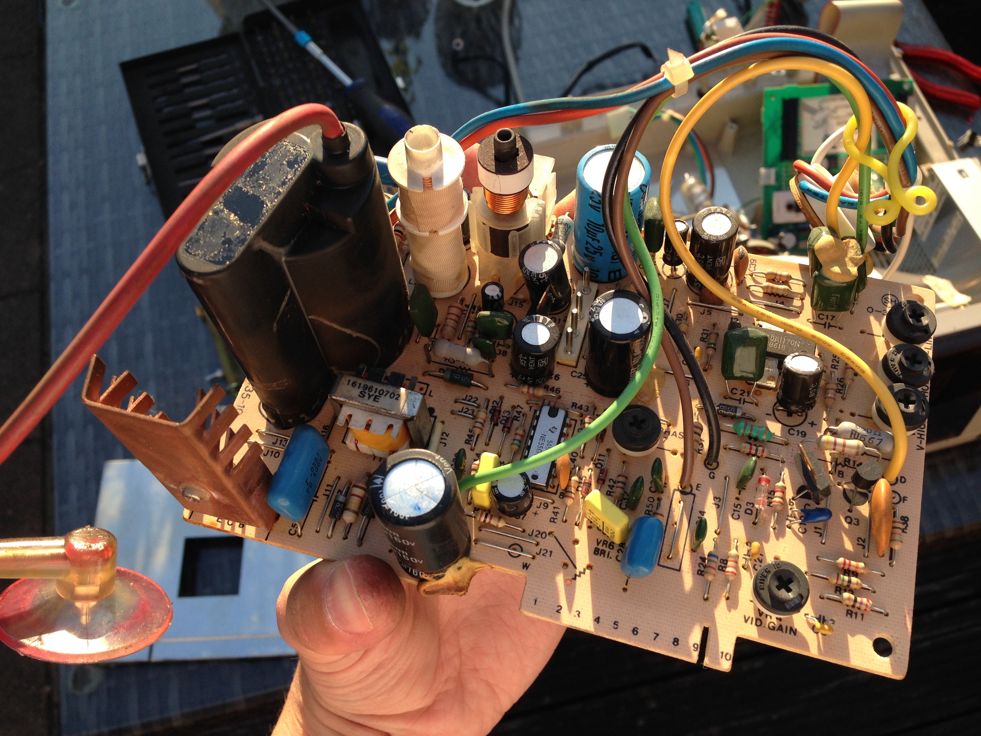
The monitor chassis almost made me go "aww that's cute" just because it's such a small and simple looking board compared to other monitor chassis's I've seen. Of course it's just a monochrome CRT, but for example up to now I've only seen assemblies where there is a neck board that plugs into the CRT instead of just a plug. Also all the common adjustment pots for the video signal are there. The board has a 10 pin edge connector that connects to the main board of the VideoWriter. It would be interesting to see what the pinout is of that one. What intrigued me was finding a 556 (dual 555) timer chip on the board. Maybe for some video signal timing?
Printer Interface
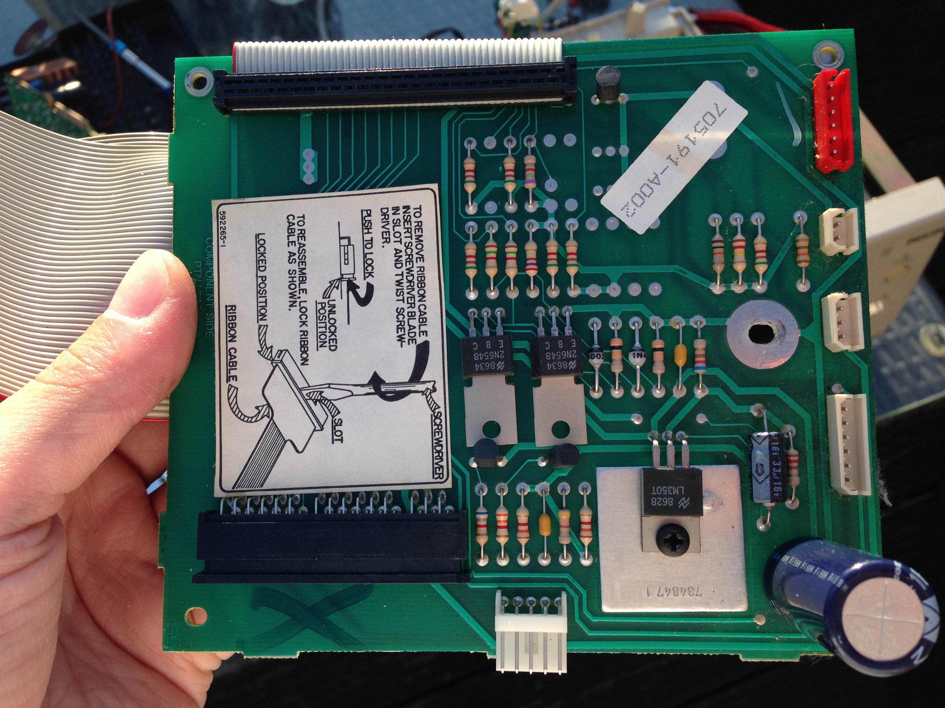
This board was actually not found under the cover, but directly under the printer mechanism. It's not very interesting I think. It connects from the main board through a big ribbon cable and from there goes to the motors, paper feed buttons, printing contrast slider, cartridge cradle, end stops and paper sensor. I'm just stalling for the best part...
Main board
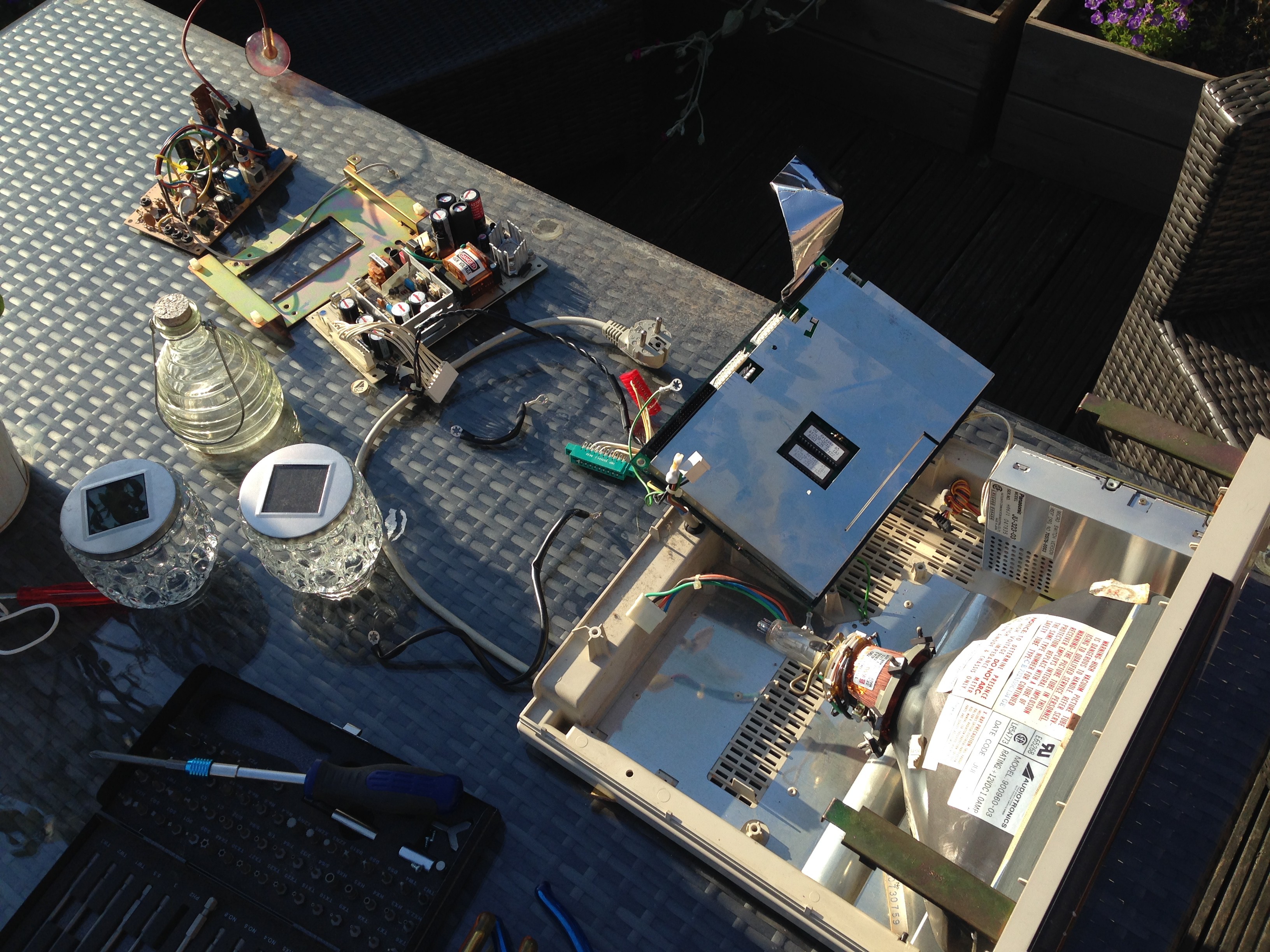
The main boad of the VideoWRITER is very interesting I think. I will spend the next logs on it. For now enjoy the board still covered by its shield and the other components spread over the garden table. But you can tell that there are at least two rom chips on the main board peaking throught the shielding. You can also see what remains in the unit: the CRT and the floppy drive.
Discussions
Become a Hackaday.io Member
Create an account to leave a comment. Already have an account? Log In.
You have to lift the top part behind the printer with a screwdriver. Unfortunately that part is one way and some little part will break on the inside. Next you see two screws left an right of the power cord. Then you have to remove a screw left of the printer motor that holds an earth wire covered in a black plastic tube. Lift the whole a bit, de-connect the flat cable towards the printer near the motherboard and you can remove the whole.
The reason I had to open my Videowriter was that I collected it yesterday and when I connected it to the main power it said POOF. I replaced the capacitor but to no good: completely dead. Power supply seemed to be OK but except a spinning floppy drive, nothing at all.
The previous owner bought it on a flea market in 1998 and stored it in an old shed. OTOH, I also collected three clone PCs, one 8088 and two 80286s, and they still worked fine.
Are you sure? yes | no
Removed the screws but still the back part didn't come of. And weird detail: those screw were 1/4 inch. What about Philips being Dutch ??? Took me quite some time to find the English tools, haven't needed them for years.
But: what are the holes in the bottom of the top photo? To be continued.....
Are you sure? yes | no
Same question but... Have a look at the three metal parts in the top of the case: two left and right of the monitor and the one left of the drive (seen from the back like the top photo). If you remove the dark cover of the printer and look inside, you'll see three screws. I think we have to remove them first. These are the only other screws I see so it probably won't leave us a choice.
Are you sure? yes | no
How did you removed the cover? I've removed 4 screws at the bottom of the machine but the cover still won't come off. Is there any clips involved? I'd rather not break anything
Are you sure? yes | no