Close
0%
0%

Connected Pool Monitor

The Connected Pool Monitor Measures the Water
Quality in Your Pool and Sends You Wireless Updates

Similar projects worth following
The Connected Pool Monitor continuously measures the water quality of your pool and tells you when you need to add pool chemicals eliminating the need for using test strips or guessing when your pool water is not clean.

The Problem

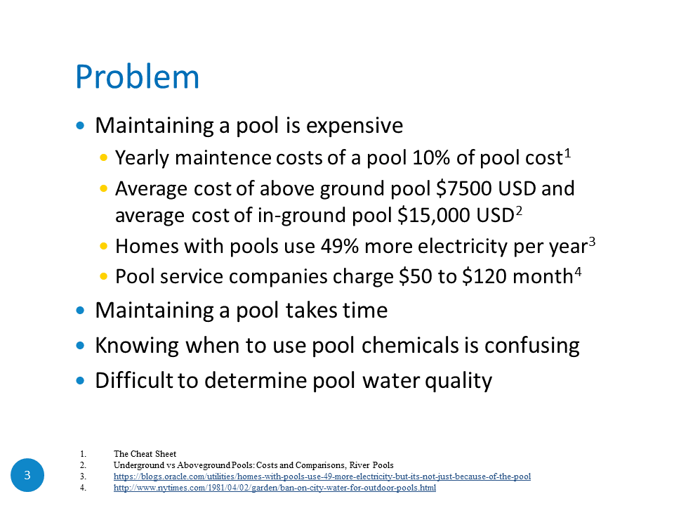
Knowing the chemistry of the water in a pool is vital to having clean and clear water. The pH of the pool water can tell you if you are having water quality issues. Adding a chemical like chlorine helps keep the water clean.

In order to know what the chemical levels are in your pool you need to manually measure them, often with test strips that give you difficult to interpret results. If you add too many chemicals at the wrong time you waste lots of money; add too few chemicals and your pool water quality won't be good enough to swim in.

The Solution

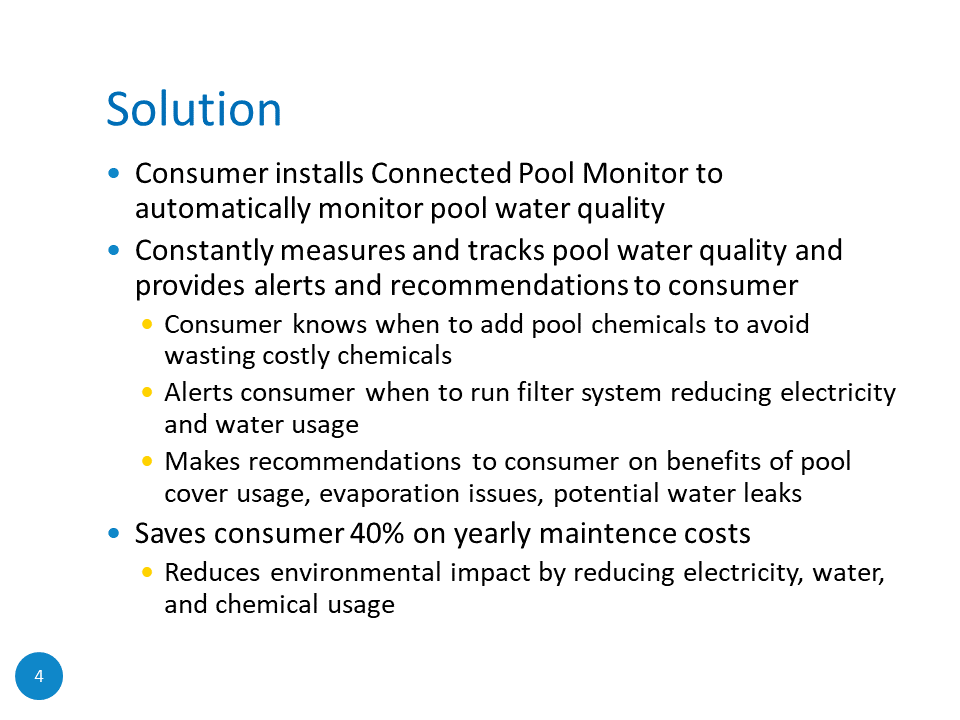
The Connected Pool Monitor solves this problem by constantly measuring and assessing the chemicals in your pool and sending you wireless updates when you need to add more chemicals. By adding chemicals at the right time to your pool you can save money and always have clean and clear water to swim in.

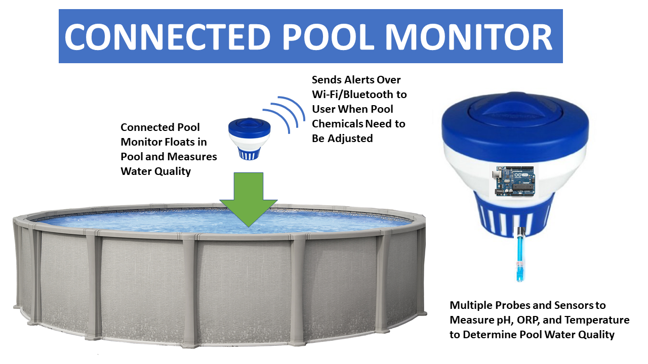
The Connected Pool Monitor uses a pH probe, ORP probe, and temperature sensor that are placed permanently in the pool to constantly measure and then assess when pool chemicals need to be added. Based on knowing the pH, ORP, and temperature different algorithms can be used to determine threshold levels of when the water quality is not optimal. Other environmental conditions such as air temperature are measured and reported as well. Future measurements could include humidity, turbidity, and UV exposure.

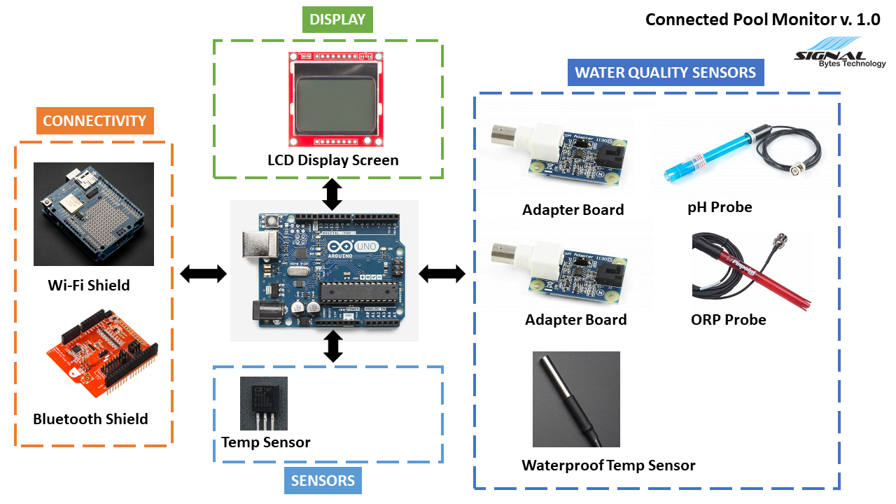
The system diagram above shows the different components of the system and how they connect together. An Arduino microcontroller is at the core of the system. The water quality sensors measure the pool water quality directly. The sensors are for environmental conditions like air temperature. The display will be for showing on the system packaging the current state of the pool water quality. Finally the connectivity is for sending wireless updates to the user either through Wi-Fi to a local web server or through Bluetooth to a mobile app.

Business Case

—Over 10 million residential pools in US
—25 million more potential pool owners in US
—More than 50,000 pool cleaning companies in US

Licensing - Software and Hardware

The following libraries are being used in this project:

- Sparkfun LCD functions library for Nokia display

- Adafruit libraries for CC300 Wi-Fi shield and DHT11 digital water temperature sensor

- Dallas Semiconductor and One Wire library for DHT11 digital water temperature sensor

- Arduino SPI interface library

Adobe Portable Document Format - 250.22 kB - 07/22/2017 at 04:16

Preview
Download

LCD_Functions.h

Sparkfun Nokia LCD display library for Arduino

plain - 18.28 kB - 07/15/2017 at 19:41

Download

nokia_lcd_temp_display.ino

Arduino sketch for displaying analog sensor to Nokia LCD display

ino - 3.76 kB - 07/15/2017 at 19:40

Download

sketch_temp_sensor_serial_out.ino

Arduino UNO R3 file

ino - 2.14 kB - 07/15/2017 at 17:06

Download

  • 1 × Arduino UNO R3 microcontroller
  • 1 × Graphic LCD 84x48 - Nokia 5110 display
  • 1 × Analog Temperature sensor - TMP36 Sensors / Temperature, Thermal
  • 1 × pH/ORP Adapter Sensors/Water Quality
  • 1 × ASP200-2-1M-BNC pH Lab Electrode Probe

View all 9 components

  • pH Pool Water Test

    Timothy Coyle07/23/2017 at 00:51 0 comments

    With my pH probe calibrated and working I took it all out to the pool and hooked it up.

    I have my Arduino with pH probe adapter board and analog temperature sensor to measure air temperature along with the LCD display to show the measured air temperature and pH of the pool water.

    I have the pH probe in a modified pool chemical floater connected to the Arduino with a cable.

    The measured result is close to 7.3 which is the pool water pH so the proof of concept works!

  • Measuring pH and ORP with Arduino

    Timothy Coyle07/23/2017 at 00:48 0 comments

    Using the phidgets pH probe and adapter board connected to the Arduino UNO R3.

    Arduino Connection

    From the user guide the adapter pin out is simply GND, 5V, and Analog Input:

    I connected the adapter cable to 5V and GND on the Arduino and I used the analog input pin A1.

    Programming the Arduino to read pH

    From the user guide there are formulas you can use and modify to calculate the pH.

    From phidget user forum site on adapting equation for Arduino connection:

    Does it means my formula will be 0.0178*(Vin*200)-1.889 as my input is (0V-5V)?

    For obtaining exact ph – sensor value equation you need two standard buffer solutions( buffer 7 and buffer 4).

    First put the electrode in buffer 7 then read the sensor value 7 then wash the electrode dry it and put it in buffer 4 solution and read sensor value 4.

    With this two point you can write the exact equation for pH -sensor value .

    From this project site they try to use linear equation to fit 2 data point calibration and phidgets site has basic information on calibrating sensors:

    2 Point Calibration using pH 4 and 7 buffer solution measurements

    m = ((7-4)/760-534)) = 3/226 = 0.0133

    b= 4 – 0.0133*534 = -3.1022

    Final Equation

    pH(cal) = 0.0133(RawSensorValue) – 3.1022

    Temperature Calibration

    You need to know the water temperature in order to properly due to the calibration. In our case I’m using the waterproof DS18B20 from Adafruit.

    Connection is 5V, GND, and a digital input pin but you also need to put a 4.7K pullup resistor between VCC and the data pin.

    Found some code for reading just the DHT11 water temp sensor (no humidity) on a different pool monitor project site or you can use the Adafruit library example.

    Programming the Arduino to read ORP

    From the user guide there are formulas you can use and modify to calculate the ORP value from the ORP probe:

    There’s no required temperature calibration for measuring ORP and can be directly calculated on the Arduino using the same equation.

    Reading pH Probe and ORP Probe with Temperature Calibration on Arduino

    Putting this all together I ran some tests first with just the pH probe with calibrated temperature coming from the water temperature probe. (*Probe not working properly so used manual temperature measurement of water for calibration)

    Below is the setup that I used with pH buffer solutions of 4, 7, and 10. I also have filtered water.

    Using pH and TDS meter following results for pH and temperature:

    You can calibrate the pH meter by adjusting a trim:

    Example measuring the pH and temperature of one of the solutions:

    Example of putting the pH probe in one of the solutions:

    Running the Arduino code I output the pH values to the serial monitor screen for debugging:

    Example serial out :

    Used a thermapen fast thermometer (digital) to measure temperature of solutions to calibrate for pH and verify TDS meter that also measures temperature is working properly:

    Using temperature compensated equation for original Pool Monitor result and then also tried the 2 point calibration for the Pool Monitor result

    Filtered Water Test

    pH meter result: 7.0

    TDS temperature result: 22 C/ 72 F

    Thermapen temperature result: 71 F

    Pool Monitor result (2 point calibration): 780(raw)/7.27 pH

    pH Buffer Solution 7.0

    pH meter result: 7.0 (after trim calibration)

    TDS temperature result: 21 C/ 71 F

    Pool Monitor result: 760 (raw)/8.8 pH

    Pool Monitor result (2 point calibration): 754(raw)/6.93 pH

    pH Buffer Solution 4.0

    pH meter result: 4.0

    TDS temperature result: 20 C/ 70 F

    Pool Monitor result: 534 (raw)/5.19 pH

    Pool Monitor result (2 point calibration): 504(raw)/3.61 pH

    pH Buffer Solution 10.0

    pH meter result: 10.0

    TDS temperature result: 21 C/ 71 F

    Pool Monitor result: 965 (raw)/12.4 pH

    Pool Monitor result (2 point calibration): 990(raw)/10.06 pH

    I found that I had to do my own 2 point calibration in order to get an accurate result. Also both the pH and temperature meter seem to be very accurate.

    With the pH probe calibrated I then...

    Read more »

  • Displaying Temperature on Nokia LCD Display with an Arduino

    Timothy Coyle07/15/2017 at 19:40 0 comments

    I’m going to start off by reading the analog temperature sensor on pin

    A0 and displaying to the serial monitor. Then I will add the Nokia LCD

    and display the temperature to the Nokia display.

    Here’s the pin connections and setup of the analog temperature sensor with the Arduino UNO R3:

    Running the code the measured temperature in my house is 70.8 F:

    Using a thermapen thermometer it says the air temperature in my house is 73 F:

    Okay now onto the Nokia LCD display.

    I’m using the Nokia 5110 LCD display from Sparkfun that will connect to the Arduino over the SPI interface:

    Sparkfun has a good guide up on how to connect and program the display to an Arduino.

    Here’s the LCD pinout for hookup from Sparkfun:

    The LED backlight supply connection doesn’t have a current limiting resistor so if you hook this up to the supply on the Arduino directly it will pull a lot of current so you should put a limiting resistor in there if you’re going to backlight the display.

    The connection of the display to the Arduino from Sparkfun:

    It’s not a bad idea to add some limiting resistors in your data connection paths as alternative hookup shown below:

    Below are some photos of my hook up:

    Running the example Sparkfun example code you can see how bitmaps are loaded, shapes drawn etc.:

    Using the Sparkfun LCD functions library and their example code I combined my analog temperature sensor code and can now read and display the sensor temperature to the display screen:

    Below is the Arduino sketch:

    /*

    Date: 7/15/17

    Version: 1.0

    Attribution:

    For Nokia LCD Display Code:

    Nokia 5100 LCD Example Code

    Graphics driver and PCD8544 interface code for SparkFun’s

    84×48 Graphic LCD.

    https://www.sparkfun.com/products/10168

    by: Jim Lindblom

    adapted from code by Nathan Seidle and mish-mashed with

    code from the ColorLCDShield.

    date: October 10, 2013

    license: Officially, the MIT License. Review the included License.md file

    Unofficially, Beerware. Feel free to use, reuse, and modify this

    code as you see fit. If you find it useful, and we meet someday,

    you can buy me a beer.

    Comments:

    This sketch reads an analog temperature sensor and writes the temperature in F to

    a Nokia LCD display

    Hardware Connections:

    Analog Temperature Sensor Connection:

    Vout Pin: Connect to analog input 0.

    LCD Display Connections:

    Graphic LCD Pin ———- Arduino Pin

    1-VCC —————- 3.3 V

    2-GND —————- GND

    3-SCE —————- 7 (digital)

    4-RST —————- 6 (digital)

    5-D/C —————- 5 (digital)

    6-DN(MOSI) —————- 11 (SPI)

    7-SCLK —————- 13 (SPI)

    8-LED – 330 Ohm res — 9 (PWM)

    */

    #include <SPI.h>

    #include “LCD_Functions.h”

    // Setting up temperature sensor

    // The AREF pin is tied to the 3.3V output pin to be used as an external reference for the ADC

    #define aref_ext_voltage 3.3

    // Assign Arduino analog input pin to be connected to temp sensor

    int tempPin = 0;

    // Assign a variable to hold the temperature sensor reading

    int tempVal; // the analog reading from the sensor

    void setup()

    {

    // Setup serial monitor to send temp readings to for debugging

    Serial.begin(9600);

    // This will setup the LCD pins and initialize the LCD

    lcdBegin();

    // Command to clear the screen

    clearDisplay(WHITE);

    // Trial and error values 40 to 60 to get right contrast on screen

    setContrast(50);

    // Need to tell Arduino that we are using an external voltage reference for ADC

    // Always have to set this first before calling analogRead() or else you could short out your board

    analogReference(EXTERNAL);

    // Allow voltage on ADC to settle out before reading

    analogRead(0);

    }

    void loop()

    {

    // Read the temperature sensor and store the value

    tempVal = analogRead(tempPin);

    // debug – print raw along reading to serial monitor

    //Serial.print(tempReading);

    // Convert the digitized number 0-1023 from the ADC into a voltage based on the reference voltage

    // For an external reference voltage of 3.3V => (ADC value) * (3.3V/1024)

    float voltageConvert = tempVal * aref_ext_voltage;

    voltageConvert /= 1024.0;

    // debug – print out the voltage

    //Serial.print(” – “);

    //Serial.print(voltageConvert); Serial.println(” volts”);

    //...

    Read more »

  • Week 2 Update

    Timothy Coyle07/15/2017 at 17:08 0 comments

    Follow along with me in this video series as I build an IoT product from start to finish – check out the project page!

    This Week’s Summary

    Here’s a summary of what happened last week on my “Designing an IoT Product” video series:

    • Entered the Hackaday Build Contest – see my project entry here. Also updated the project page with some new graphics and BOM (bill of materials).
    • Overview of Connected Pool Monitor

    • System Diagram

    • Current Bill of Materials

    • Got an analog temp sensor working with Nokia LCD display to show air temperature on Arduino. This will be the base setup for reading probe sensors next.
    • Was planning on setting up and testing Bluetooth Arduino shield.(do it next week)
    • Did some research and wrote up some stuff on how pH probes work and understanding water quality measurements. Should discuss that making probes would be out of scope of production – need to define your limits when making a production part and leave some things up to other companies that you can buy from or partner with. I could however (and probably will) make my own probe adapter circuits for better integration and smaller PCB foot print down the road.
    • Talk about pool water quality:

    Design Notes and Current Challenges

    • Probes: Will I need Alkalinity and maybe other probes to get more accurate results? This would increase cost a lot.
    • Features 2.0: Right now only telling user when to add chemicals – what if system did it for you? Could start by just adding shock since it’s most common one that needs to be added every couple of weeks. Then would also have to control the pool filter when to turn on/off and maybe add remote options for controlling it and setting on timer. Would definitely add complexity to the project but make more useful and maybe next level product compared to available competing products.

    Business Notes and Current Challenges

    • Going to attend free webinar “Getting Your Hardware Startup Ready for Investment” hosted by Startup BootCamp IoT on July 6 to see what they have to say about trying to take your hardware prototype to market.
    • Read an article about a hardware accelerator called Hax and signed up for their newsletter.

    Plans for Next Week

    • Get pH probe and conversion board up and running with Arduino board with LCD display. Compare results to commercial stand-alone pH meter to test accuracy.
    • Test Bluetooth shield with Arduino.

  • Air Temperature Analog Sensor Reading With Arduino

    Timothy Coyle07/15/2017 at 17:05 0 comments

    One of the sensors I'll be using in the connected pool monitor is an analog sensor (Analog Devices TMP36) to read the air temperature and display to the user.

    Analog Devices TMP36 Temperature Sensor

    The TMP36 is an integrated circuit from Analog Devices (datasheet here)that provides an output voltage that is linearly proportional to the temperature in Celcius. It can measure the temperature from -40C to +125C with a resolution of 10mV/C degree and can be powered from a 2.7V to 5.5V supply. The output voltage is 750mV at 25C with an offset voltage of 500mV to account for negative temperatures.

    lcd arduino

    Since the TMP36 outputs an analog voltage you will use the built-in Analog-to-Digital Converter (ADC) of the Arduino. The TMP36 is a 3 lead device and has 3 pins: VCC, GND, and VOUT where you will connect VOUT to one of the analog input pins of the Arduino Uno.

    lcd arduino

    Looking at the graph above you can see the linear relationship between the sensor output voltage and temperature which makes writing the code to figure out the temperature pretty easy to do.

    Using the ADC

    In order to use the ADC properly we first need to understand how it works. An ADC will take an analog voltage and then convert it to a digital value by continually sampling the signal. The accuracy of an ADC depends on the resolution. The Arduino Uno has a 10bit ADC so that means you can subdivide or quantasize the signal into 2^10 values or 1024 values. So when you read an analog voltage from a sensor it will translate the voltage on a scale from 0 to 1023 where the upper limit (5V in Arduino case) will be 1023.

    To get better accuracy you can use the external reference voltage for your ADC measurements. By default the Arduino Uno uses the 5V internal power supply for the ADC reference voltage. This is fine if your sensor outputs voltage values up to 5V but what if it doesn't? For example the TMP36 outputs 750mV at 25C but the Arduino is still using 5V as the 100% voltage range. The step size returned from reading the ADC on the Arduino is 1024/5V giving a step size of 4.88mV. Instead you can apply a lower voltage the AREF pin which will result in a smaller step size and better overall accuracy of your sensor. Different Arduino boards have internal and external references that you can use and it's best to consult the Arduino website and look at the examples.

    Hardware Setup

    In this example I hook up the TMP36 sensor to one of the analog input pins on the Arduino Uno and then I tie the 3.3V output supply from the Arduino to the AREF pin using it as an external reference for the ADC to get better accuracy. (When I used the default 5V supply for reference I did notice a bigger temperature difference by about 6 degrees compared to using the external reference) I am also using the LCD from a previous example to display the measured temperature.

    lcd arduino

    Temperature Sensor Sketch

    For the code you need to read the analog input pin and then convert the value to voltage from the ADC. Then you need to convert the voltage to the temperature based on the TMP36 datasheet.

    The sketch below reads an analog pin connected to the sensor and displays the result to the serial monitor.

    //
    //Date: 6/16/17
    //Version: 1.0
    //
    //Comments:
    //This sketch reads an analog temperature sensor and writes the temperature in F to the serial monitor
    //
    // Analog Temperature Sensor Connection:
    // Vout Pin: Connect to analog input 0.
    //


    // The AREF pin is tied to the 3.3V output pin to be used as an external reference for the ADC
    #define aref_ext_voltage 3.3


    // Assign Arduino analog input pin to be connected to temp sensor
    int tempPin = 0;


    // Assign a variable to hold the temperature sensor reading
    int tempVal; // the analog reading from the sensor


    // The setup runs once when you press reset or power on the board
    void setup() {


    // We'll send debugging information via the Serial monitor
    Serial.begin(9600);

    // Need to tell Arduino that we are using an external voltage reference for ADC
    // Always have to set this...

    Read more »

  • Week 1 Update

    Timothy Coyle07/15/2017 at 16:58 0 comments


    Follow along with me in this video series as I build an IoT product from start to finish – check out the project page!

    This Week’s Summary

    Here’s a summary of what happened last week on my “Designing an IoT Product” video series:

    Design Notes and Current Challenges

    • Probes: There are some cheaper probes available but some of them are not intended to be left in liquid for a pro-longed period of time so need to be careful what I purchase. Also some specifically state that they are not for use in salt water – probably because they will corrode quickly. I bought a pH and ORP probe that should be good to leave in my pool to test for extended period of time. I have a sand filter so don’t have to currently worry about salt systems yet.
    • Going to focus on using Arduino board with probes and sensors submerged in pool to get first prototype working. Most important question to answer is can the probes be used to accurately predict overall water quality? Can this data be translated to customer in a way they understand it i.e. it’s time to add chlorine to your pool etc.
    • Espressif ESP8266 only has one analog input so may not be enough for number of analog probes/sensors I want to use. The ESP32 would be perfect but as of to date it’s not quite ready for mainstream use. Sticking with Arduino is fine for time being but adding Wi-Fi and Bluetooth to it is more cumbersome and expensive potentially.
    • Don’t like the screen options available on market for Arduino. Mostly character LCD screens or basic graphic LCD displays – neither option seem to be good fit for end product. Need to see what else is out there. I know 32 bit microcontrollers from ST Micro and Microchip have really good graphics options.

    Business Notes and Current Challenges

    • Final product will need high end (more expensive) probes that can withstand salt.
    • What’s the breakdown of sand to salt to other pool filtration systems in the US? Need to get some numbers on this.
    • How important is the physical display screen to end product? Will an LCD text display be good enough? Do I need a more advanced graphics display like color? Important decision to make after working prototype is proved out.

    Plans for Next Week

    • Get pH probe and conversion board up and running with Arduino board with LCD display. Compare results to commercial stand-alone pH meter to test accuracy. [Doesn’t look like I will be getting the probes until end of next week]
    • Need to do more research on how to use measured pH and ORP to predict pool water quality. Chlorine levels? Try to compare to pH strips that report 6 or 7 chemicals.
    • Need to start thinking about packaging and how to put probes in pool and how to make a quick prototype.

View all 6 project logs

Enjoy this project?

Share

Discussions

Catalyst wrote 02/09/2022 at 05:53 point

I cannot see the images

  Are you sure? yes | no

Similar Projects

Does this project spark your interest?

Become a member to follow this project and never miss any updates