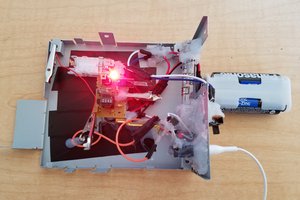
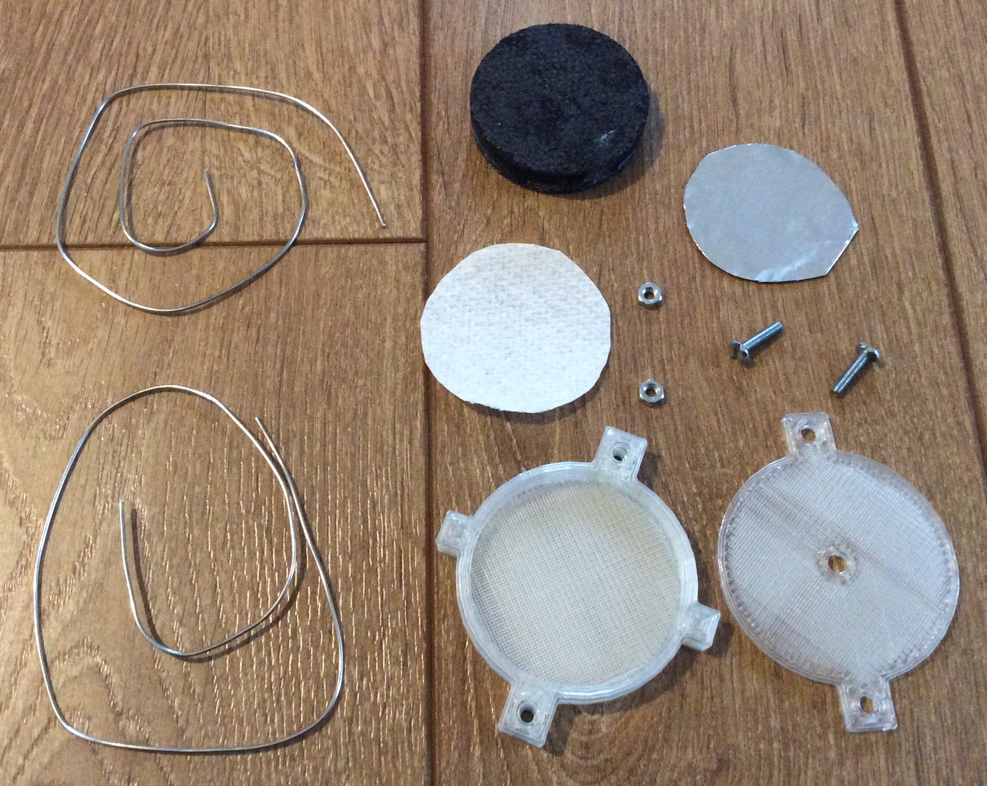
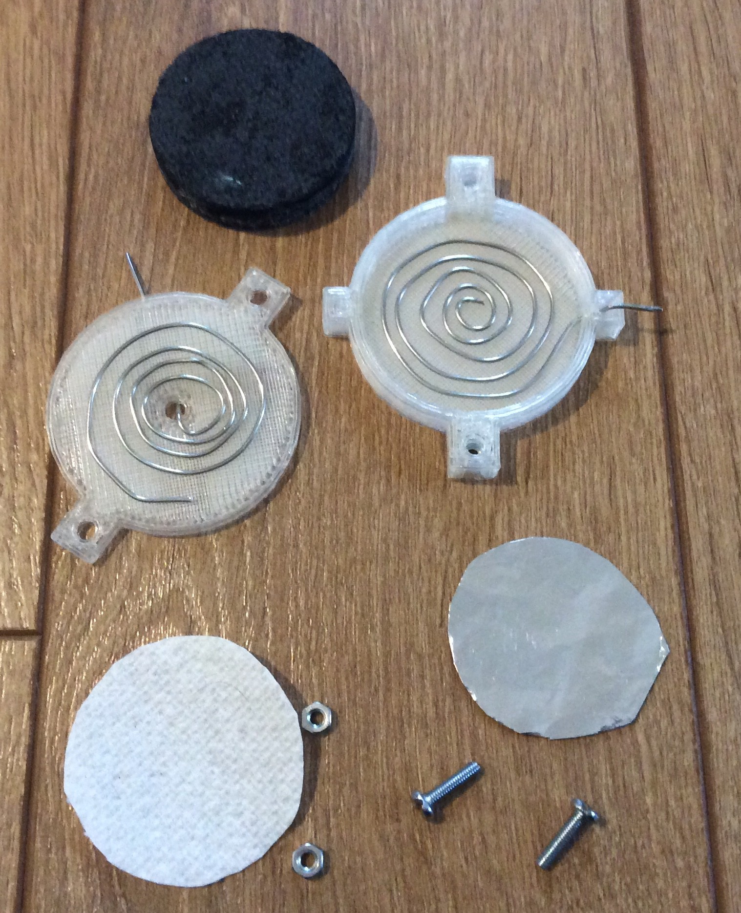
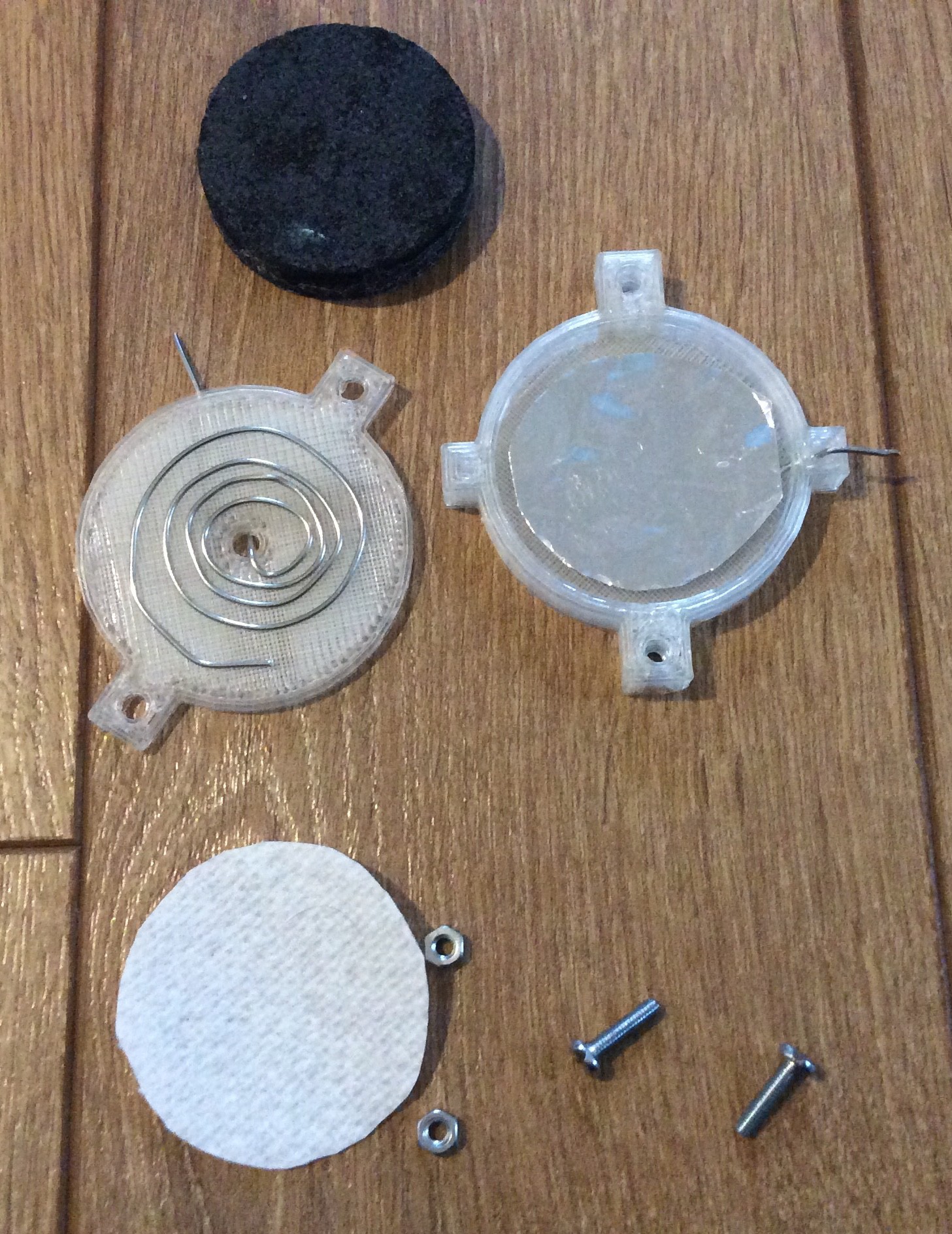
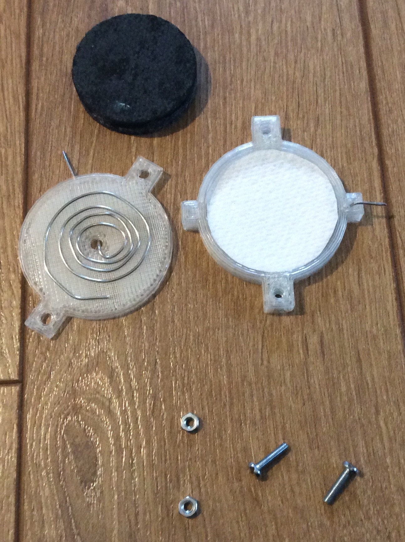
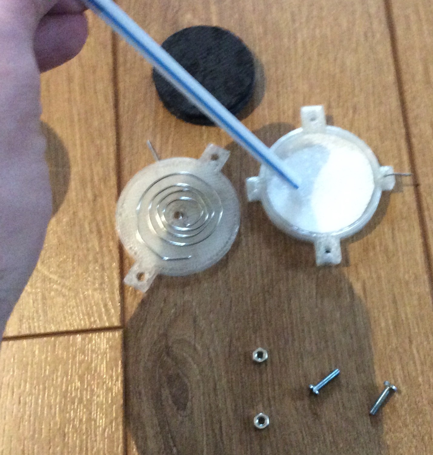
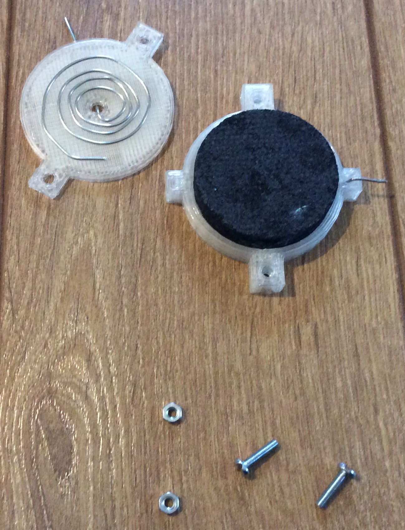
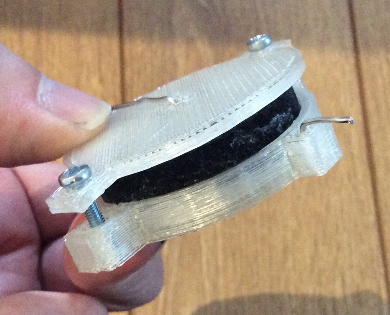
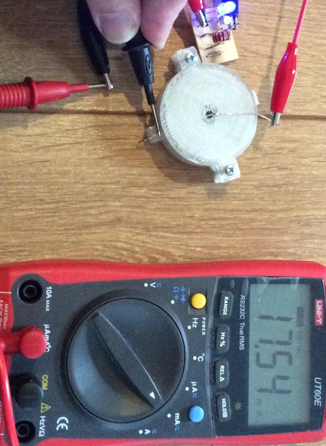
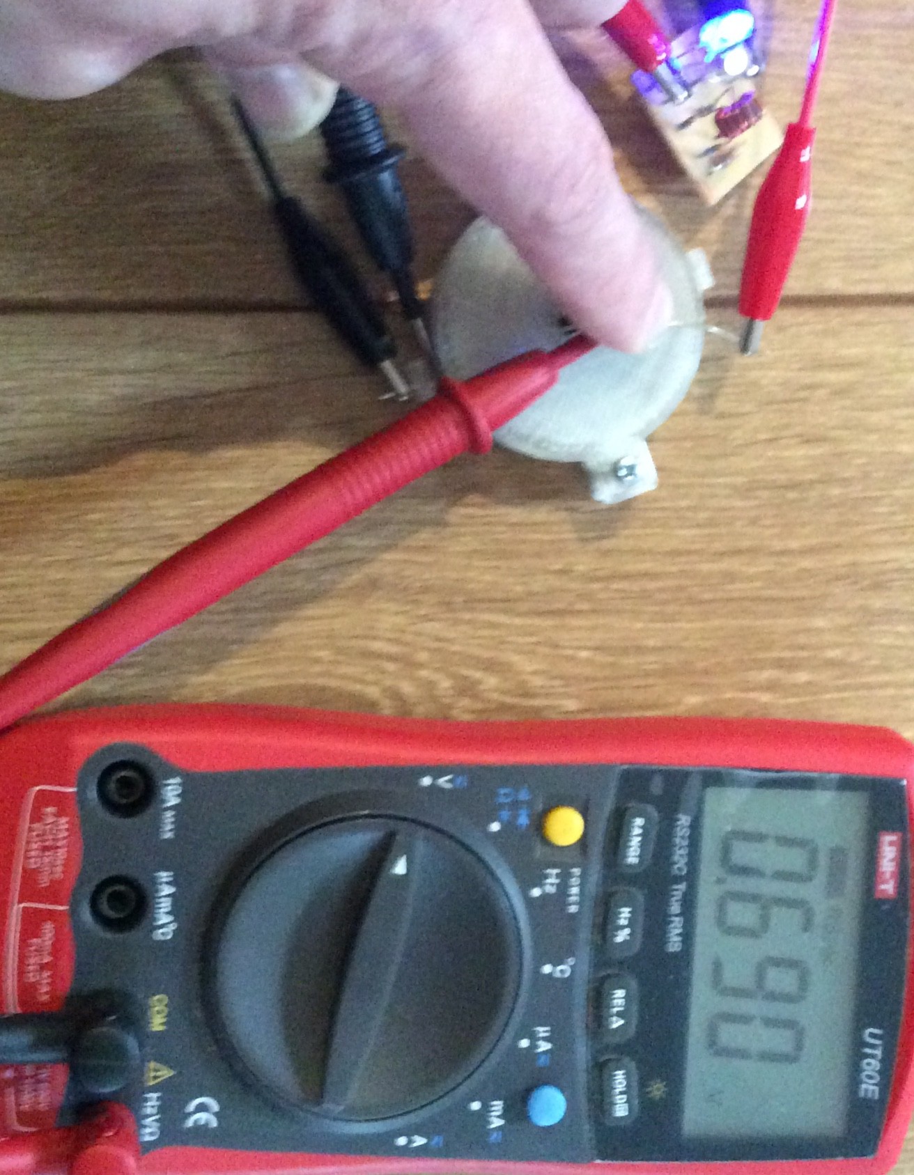
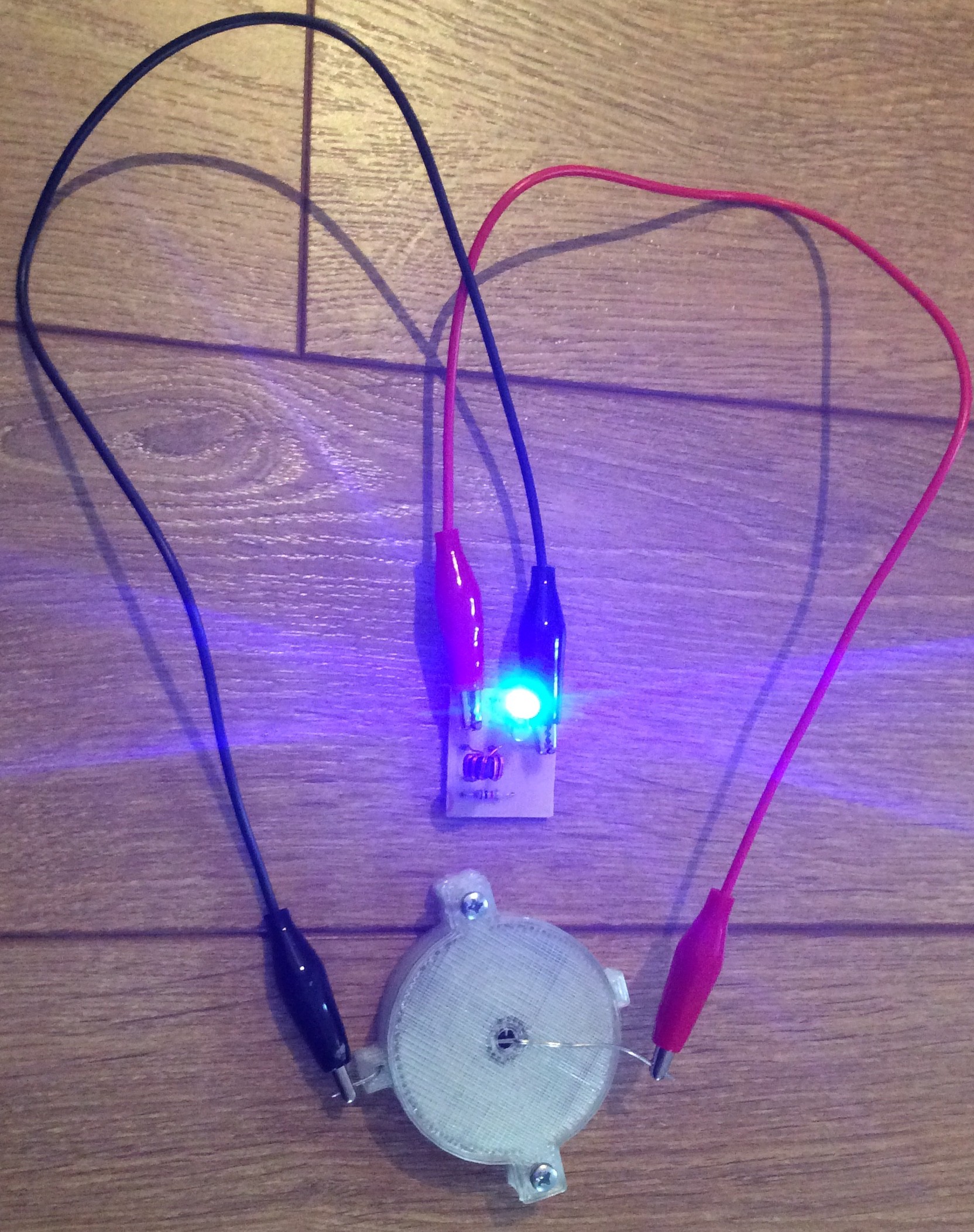
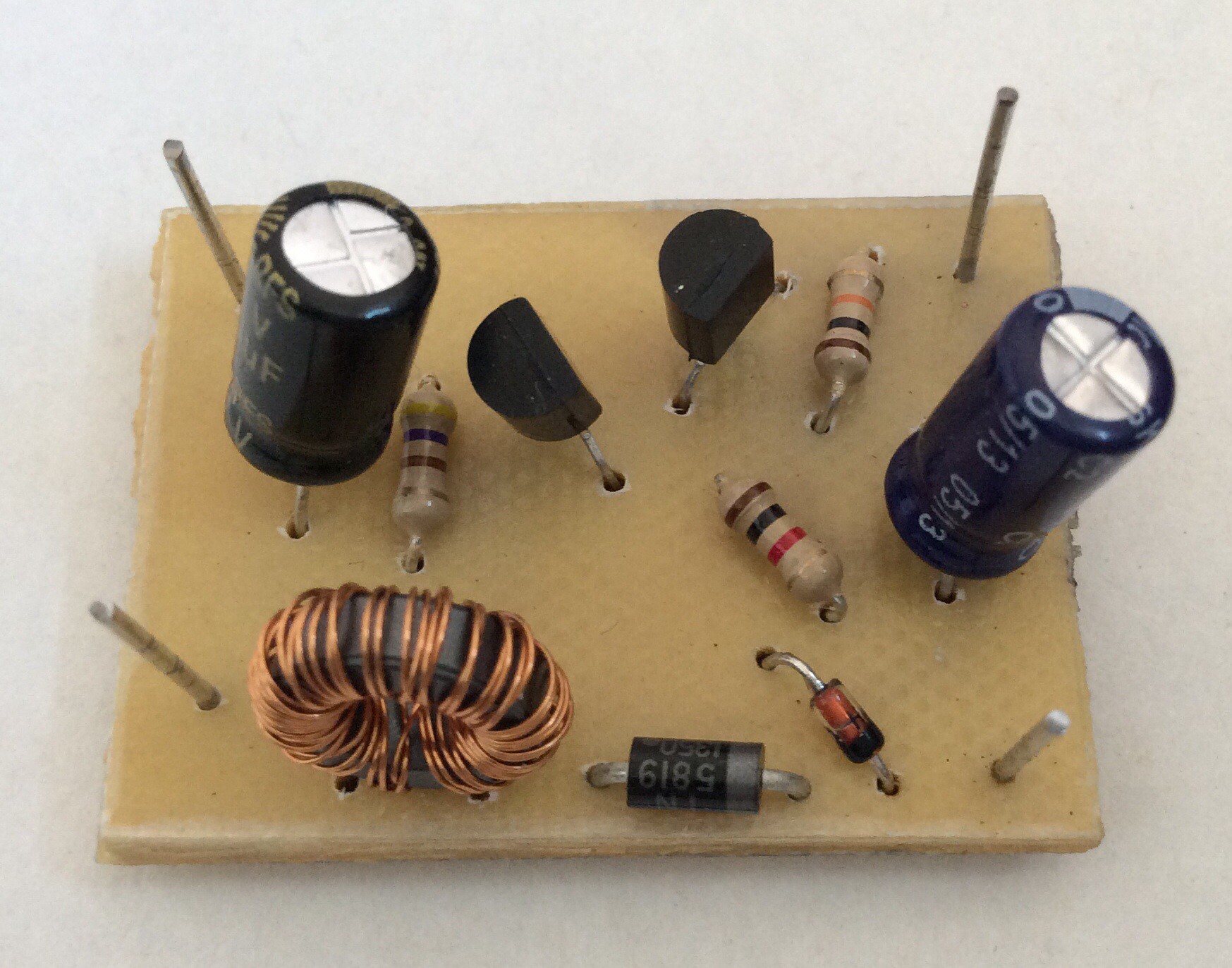
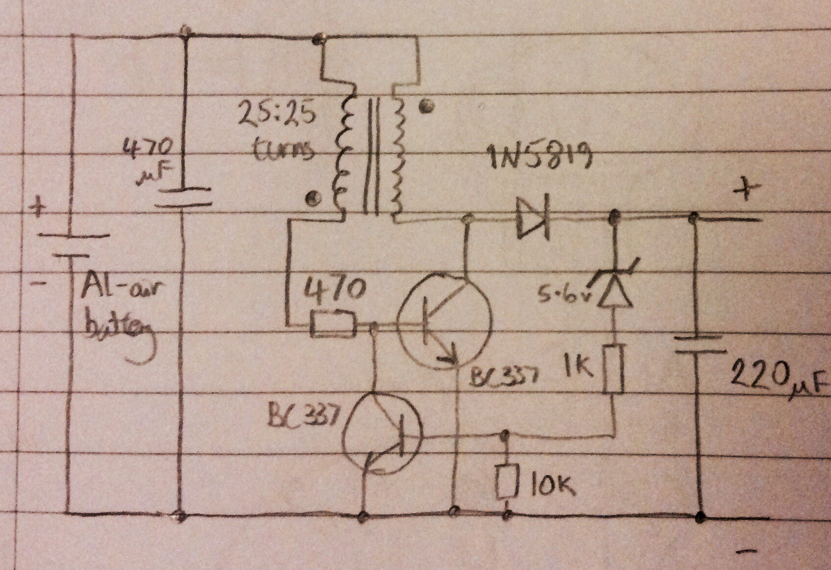
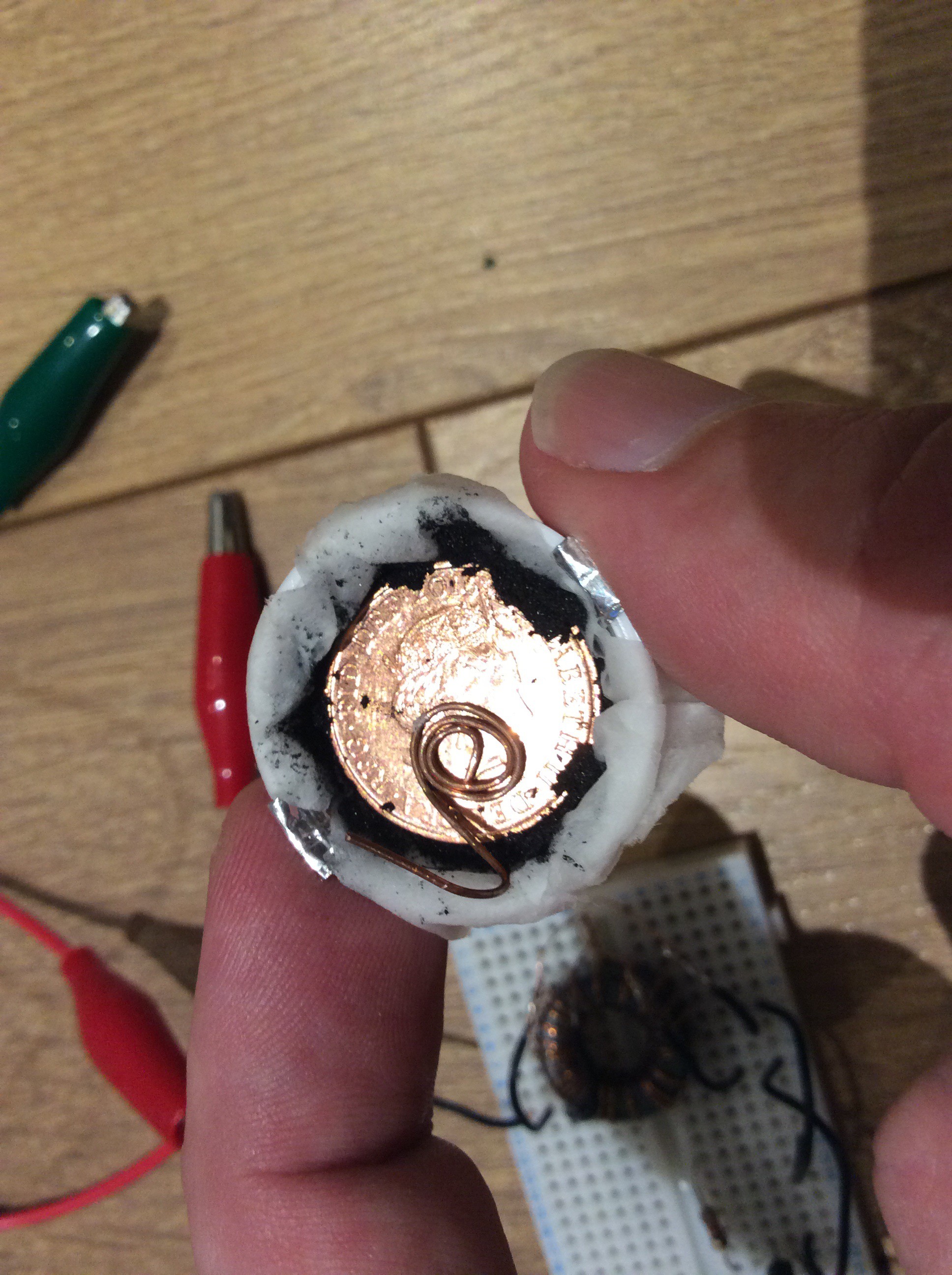
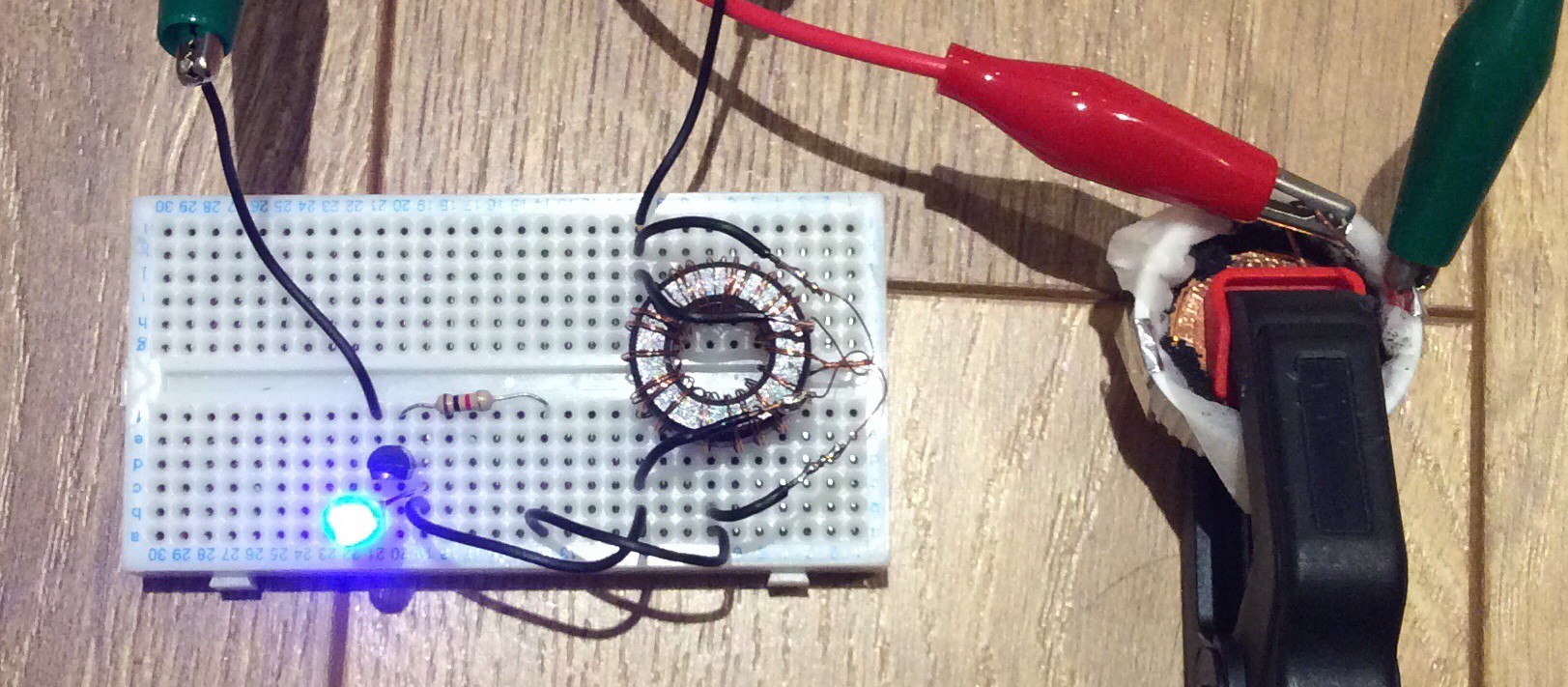
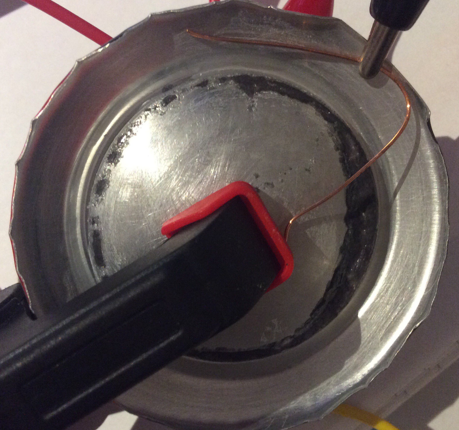
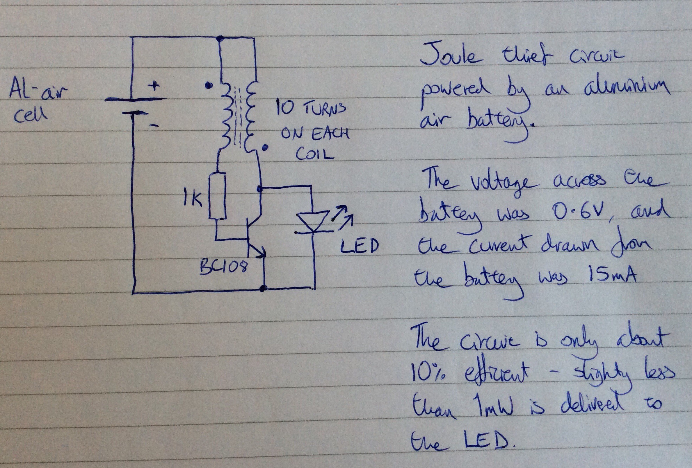
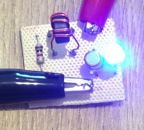
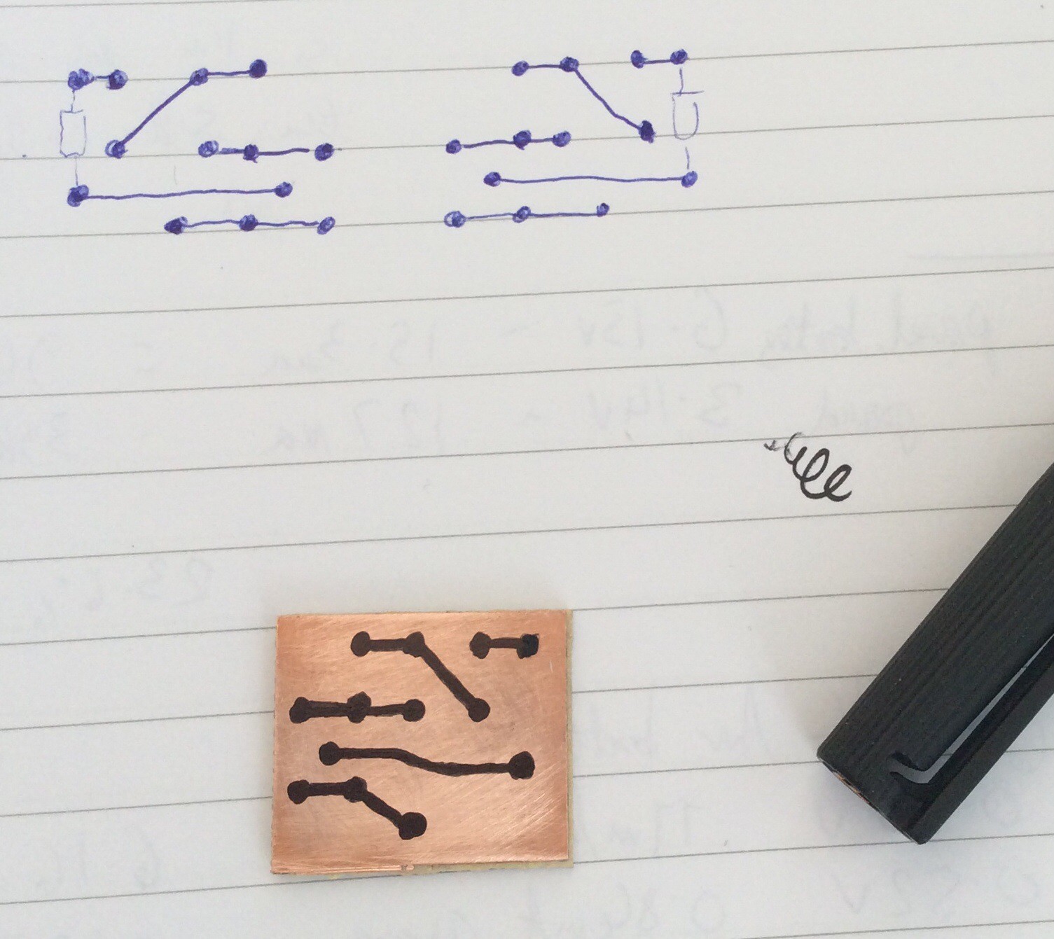
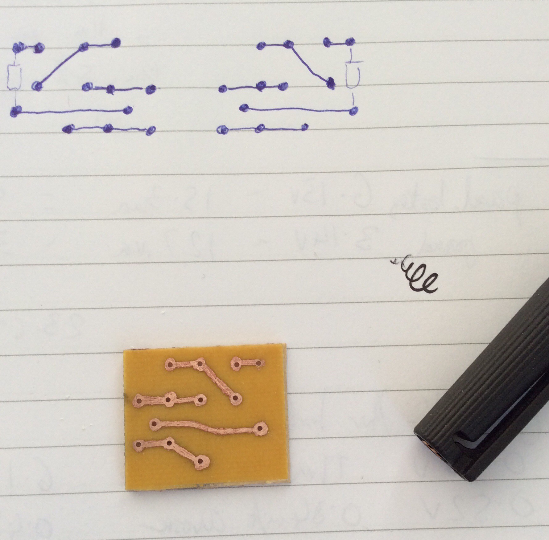
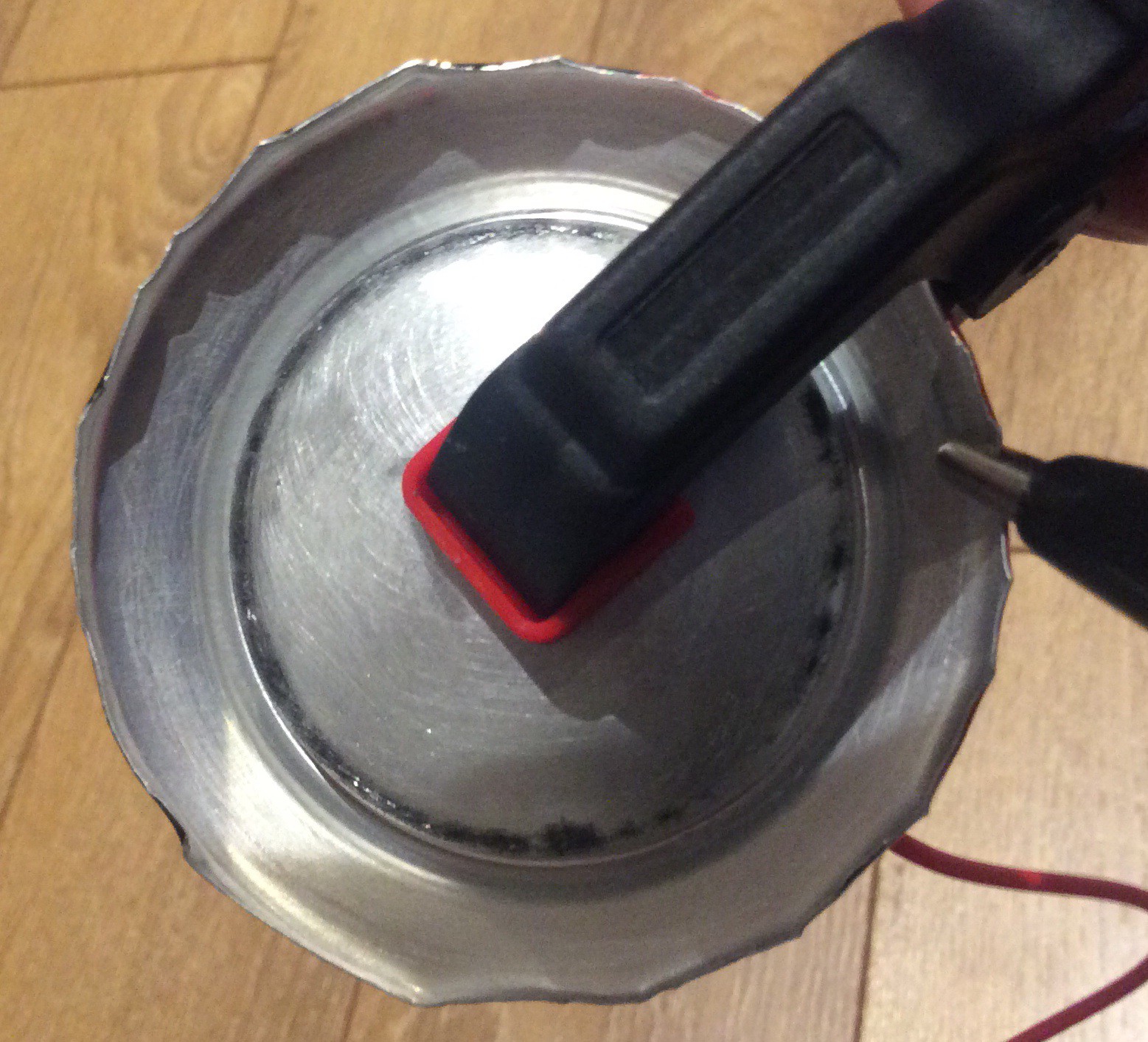
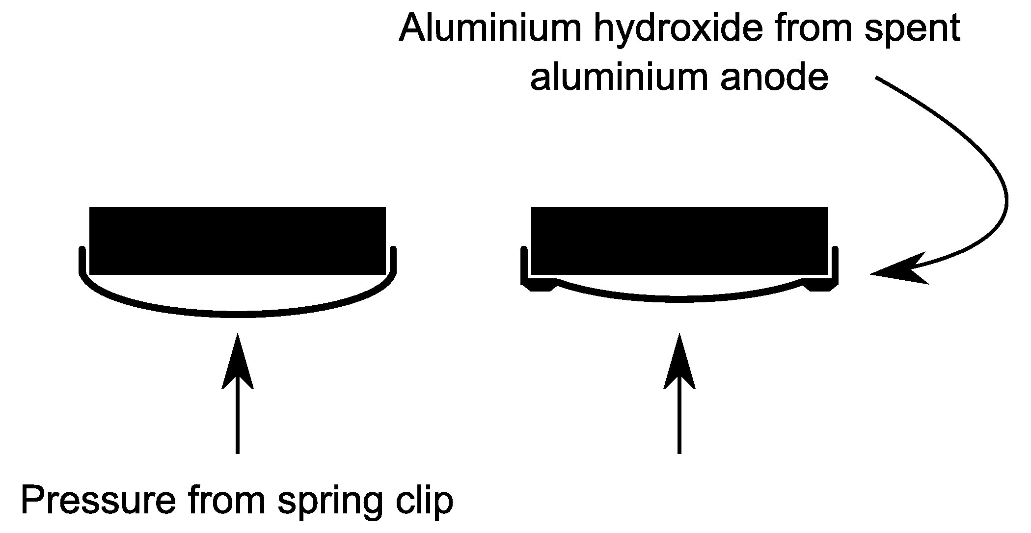
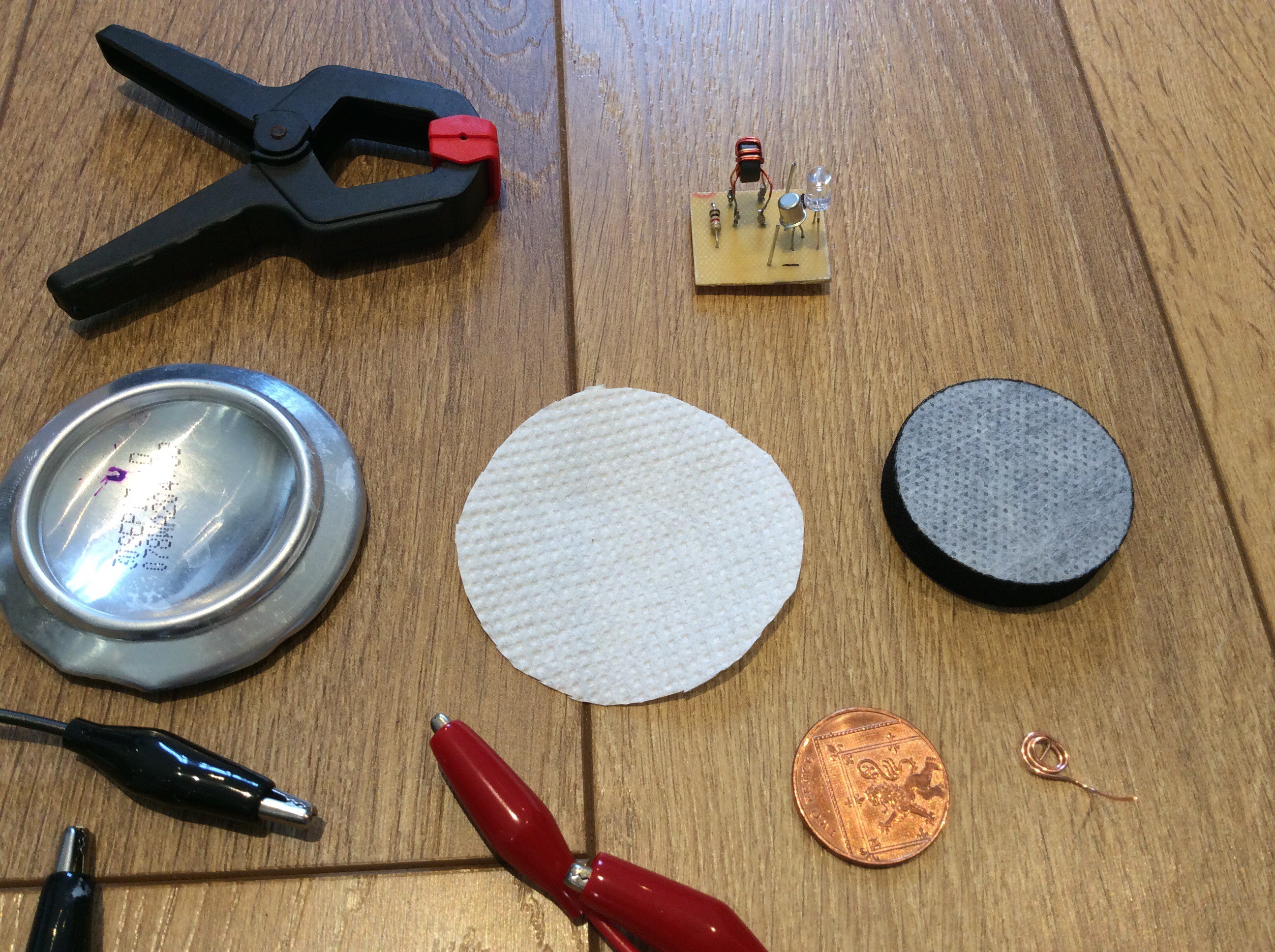
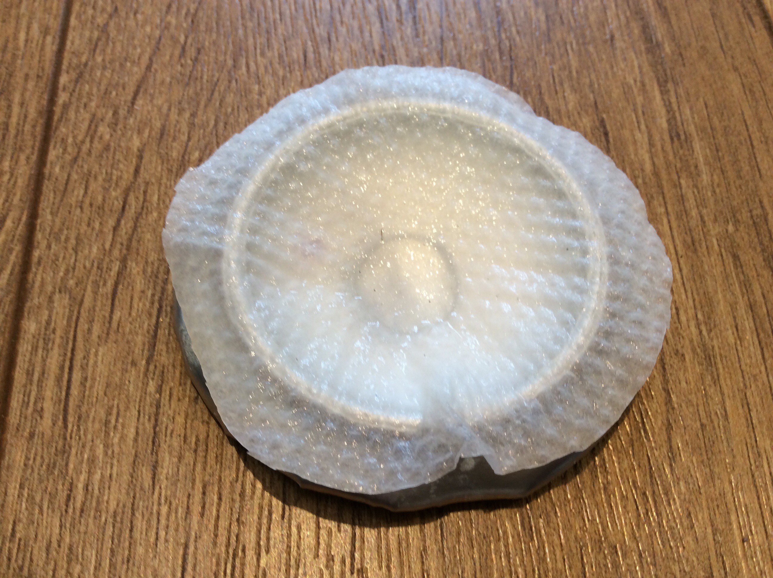
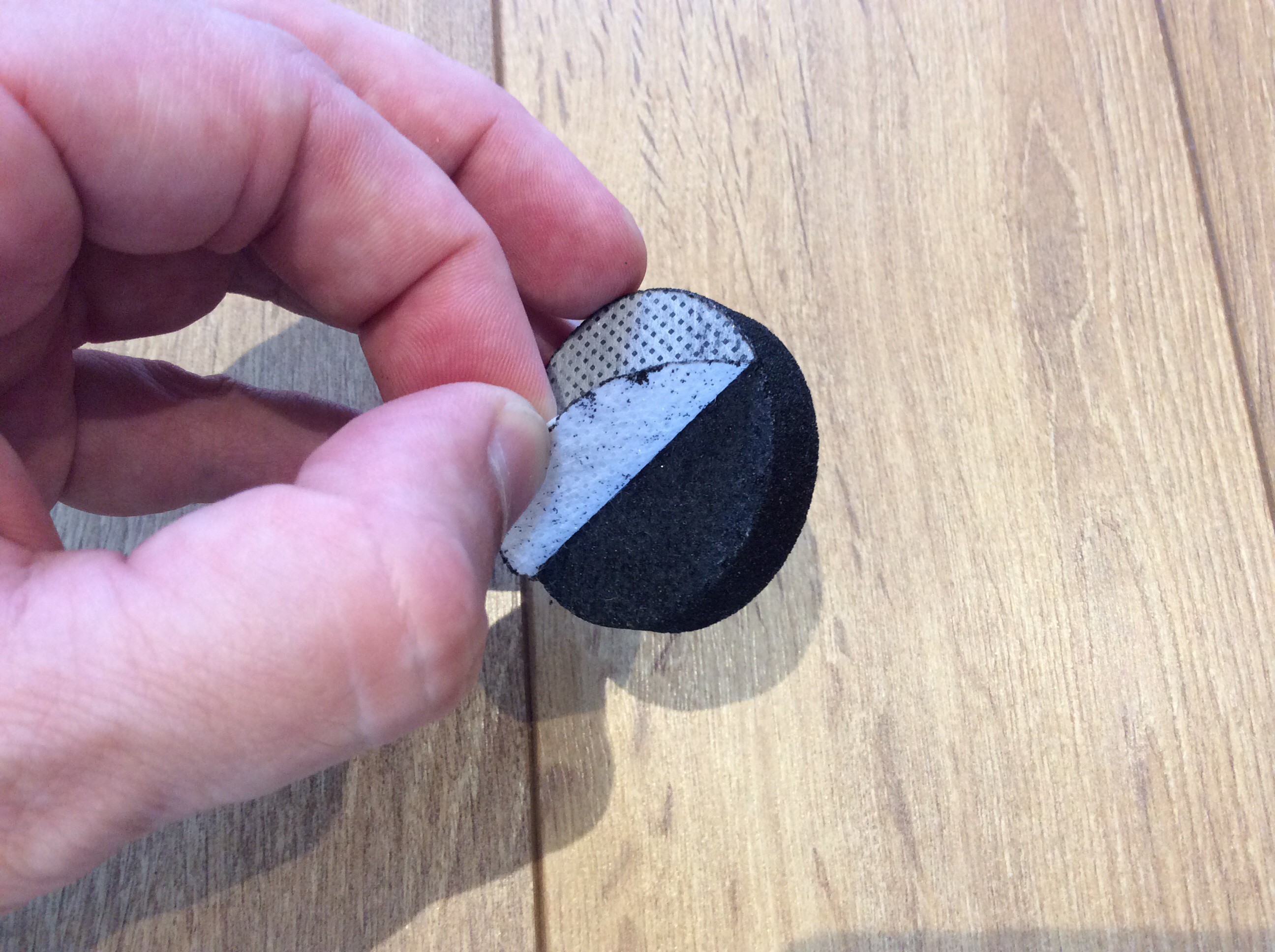
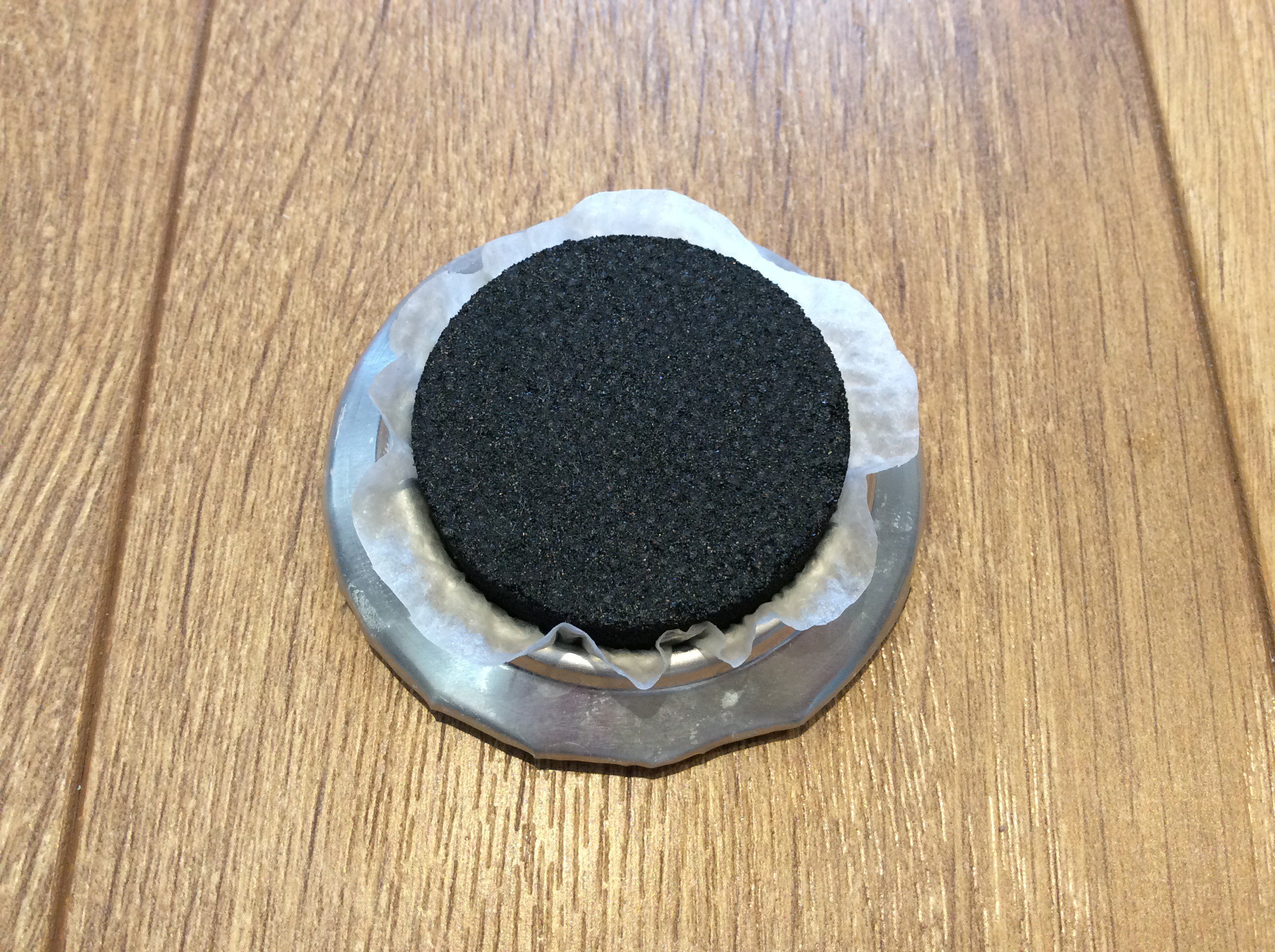
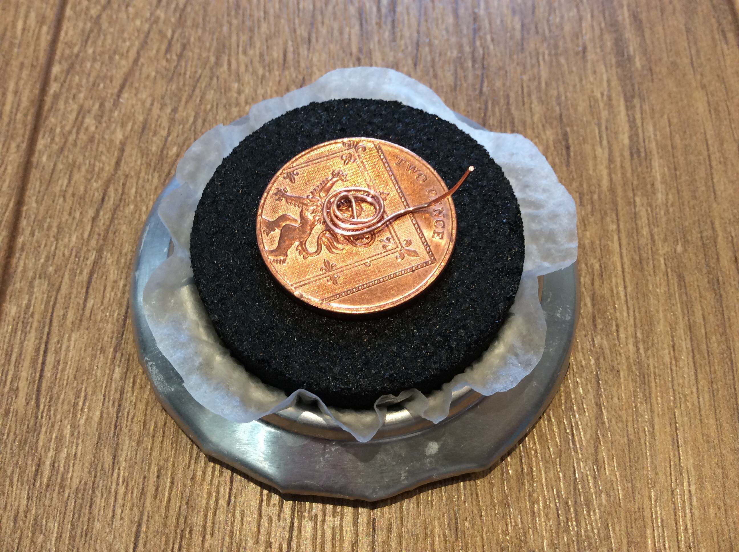
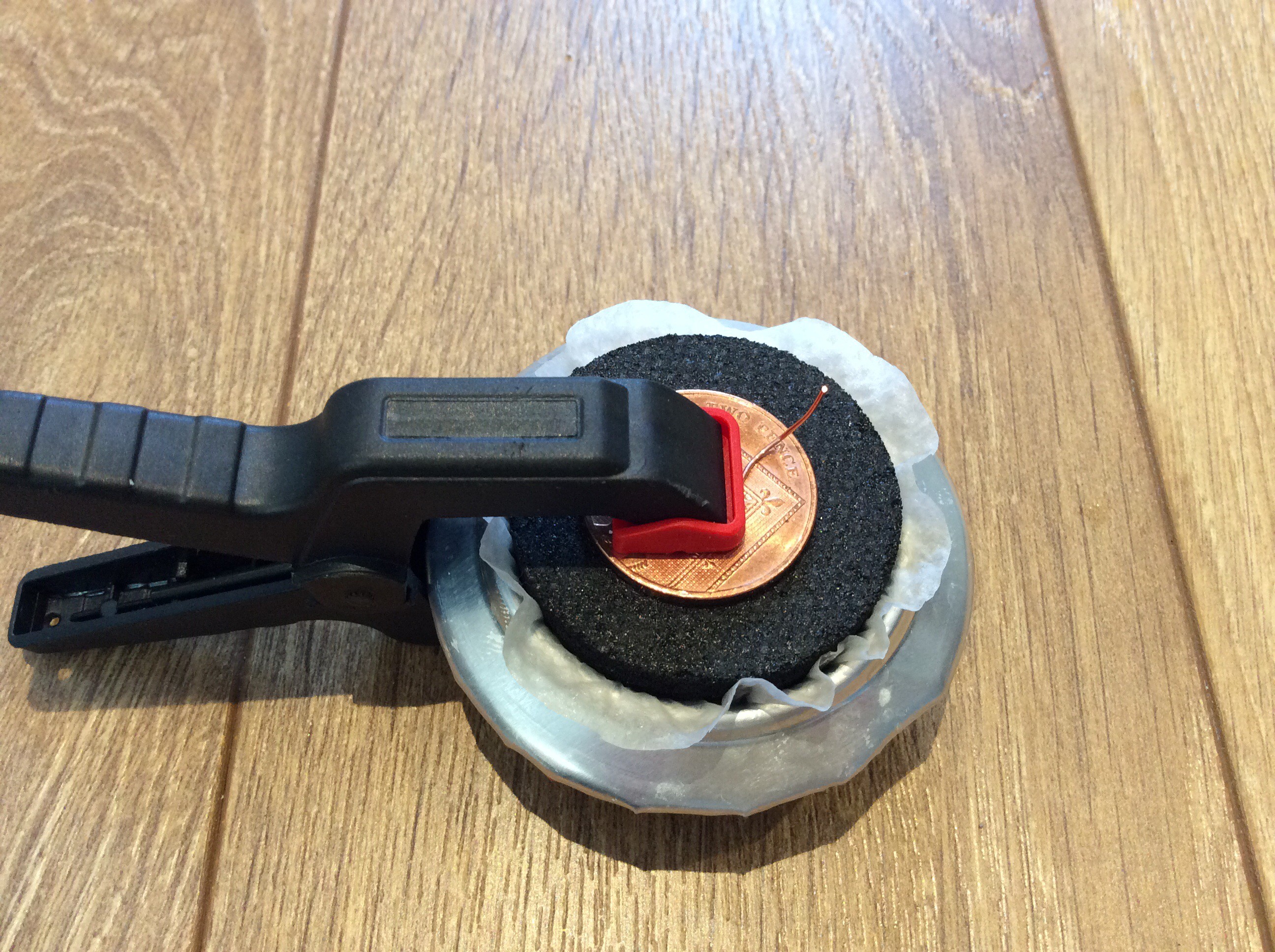
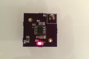
• A battery case

    will.stevens01/05/2018 at 12:32 0 comments

    I decided to 3D print a case for an Al-air cell. The diameter of the case is just large enough to hold a charcoal water filter disc. Ideally I would use a thinner disc, but the size that I am using happens to be available cheaply. The photos below show how the battery is put together. Note that the photos show two 12mm M3 bolts, but I ended up using 20mm bolts, not 12mm. The bendy wire shown in the photos is lead free solder with a tin content of 99.3%, chosen because it is unreactive. I used aluminium foil folded over four times and cut into a disc shape as the energy source. In the fourth step, 4 drops of saturated salt water solution are dropped onto the tissue paper.

    After it was assembled, the cell produced 12mW when powering a joule thief, as shown below:


  • Joule thief with regulated output

    will.stevens09/07/2017 at 21:15 7 comments

    This is a more efficient joule thief than my first attempt, shown in an earlier log entry. The efficiency of this circuit (i.e. power output from circuit / power output from Al-air battery) is about 60%. (My first attempt was only about 10% efficient. I believe that either the choice of transistor was incorrect on my first attempt, or I didn't have enough turns of wire on the transformer).

    The voltage produced by the circuit is regulated - the Joule thief discharges into a capacitor, and the Zener diode effectively turns the joule thief off when the target voltage is reached, and on again when the voltage begins to drop. Initially I used a 5.1V Zener diode, and found that this resulted in 4.6V at the output. A 5.6V Zener diode gives 5.5V at the output. After making this I found an almost identical circuit here: http://www.electro-tech-online.com/articles/the-scavenger-a-joule-thief-inspired-boost-regulator.594/ 

    (The circuit in the link has a couple of extra components which I believe are to help prevent potential transistor damage damage and to smooth out ripples at the output).


  • Some other cell designs

    will.stevens07/11/2017 at 20:58 0 comments

    Here are two more aluminium air cell configurations. In the photo below a disc of aluminium from a can is cut out and used for the anode. Separated from it by a disc of saltwater-soaked toilet paper is an activated charcoal disc from a water filter sliced in two. On the other side of the charcoal is some copper tape (from a garden centre, normally used to keep slugs off plants). A spring clip holds it all together, and holds the terminal wires in place. This battery can provide enough power to drive a small motor. The motor draws 11mW.

    The second configuration is smaller and fits in a bottle lid. A small disc of aluminium sits on top of a strip of aluminium foil in the bottom of the bottle lid. Toilet paper soaked in salt water sits above this. Half a teaspoonful of powdered activated charcoal is placed on top of the toilet paper, and a coin is placed on top of this. A spring clip holds it together and holds a wire terminal against the coin. This battery supplies 1.5mW at startup - enough to power the joule thief. The activated charcoal in this battery is homemade (a piece of pine charcoal from a camp fire).

  • After 1 week

    will.stevens07/09/2017 at 20:24 0 comments

    The aluminium can base is now very eroded. Electrolyte has begun to leak out. Because there is aluminium hydroxide dissolved in it, the electrolyte is sticky. The cell is still producing 2mW - enough to light the LED.

  • Further erosion of the aluminium anode

    will.stevens07/06/2017 at 20:43 0 comments

    In this photo you can see that after 4 days the anode has eroded even further, and that the erosion is not even. Why the right hand side is eroding more than the left is not clear. It could be because of the position of the crocodile clip, it could be that the coin on the other side of the charcoal disc is off centre, or it could be for some other reason. In this photo you can see the copper wire mentioned in an earlier log entry that will prevent the centre of the anode becoming electrically isolated from the rim.

    The cell seems to be able to produce a steady 5mW, and has done so for 4 days. So far it has provided about 4*24*3600*0.005 J = 1728 Joules of energy. For comparison, a Zinc Carbon AA cell (the lowest capacity primary AA cell available) can provide about 5000 Joules.

  • Joule thief

    will.stevens07/06/2017 at 20:11 0 comments

    The joule thief is a very simple circuit to make. The Wikipedia article about the joule thief describes the circuit and how it works. This page has a helpful description of boost converters, which helps with understanding the joule thief circuit.

    Below is the circuit diagram for the variant that I made:

    And here is a photo of the circuit:

    Any general purpose NPN transistor should work. The ferrite ring transformer that I've used was salvaged from an old computer circuit. It has 10 turns per coil, but I believe that a larger number of turns (20 say) would result in a more efficient circuit.

    The power being input to the circuit from the Al-air cell is about 5mW, and the power being supplied to the LED is about 0.5mW, so the efficiency of the circuit is only about 10%. The power output from the cell varies over time. Initially it was 9mW. It slowly declines, in part because the water in the electrolyte both evaporates and gets used up in the anode reaction. The water needs to be topped up periodically (once a day). Whenever the water is topped up the power output increases again.

    The PCB was produced by hand-drawing the tracks, as shown in the before and after etching photos below. For small circuits like this hand-drawing is quick. I find it helpful to first draw the tracks on paper as if viewed from the component side, then draw the mirror image, then draw onto the copper-clad board.

  • Aluminium anode

    will.stevens07/03/2017 at 23:03 0 comments

    The circuit has been running for about 30 hours, and it's interesting to see how the aluminium anode is being eroded. The photo below shows a dark ring where the aluminium has been eaten away (converted into aluminium hydroxide) in the reaction that generates the electrical energy.

    Aluminium is probably being consumed elsewhere too, and the dark ring shows the places where it has been consumed the most. It is already evident that the pressure of the spring clip gradually brings more of the can base into closer proximity to the charcoal disc. The diagram below illustrates this (the tissue paper barrier between the charcoal and aluminium is not shown in this diagram).

    It's convenient to have the anode "fed" towards the cathode like this. A potential problem is that the connection from the anode to the circuit (crocodile clip in the photo above) is outside the dark ring, and will eventually (quite soon by the looks of things) become separated from the inner part of the anode. To resolve this I've inserted a piece of copper wire under the spring clip and put it into the jaws of the crocodile clip.

  • Aluminium-air cell

    will.stevens07/02/2017 at 20:30 0 comments

    This cell is made from the base of an aluminium soft drinks can, a disc of tissue paper soaked in saturated salt solution, and an activated charcoal disc for a water filter. The image below shows these components.

    The charcoal disc is soaked in salt solution for 10 minutes before assembling the battery. The tissue paper is placed over the can base, then a few drops of salt water solution are dripped onto it, as shown below.

    The two thin fibrous membranes attached to the charcoal disc are peeled off, then the disc is inserted into the hole in the can base. Coincidentally, it is a snug fit. Take care not to tear the tissue paper.

    The can base serves as the negative terminal of the cell. The positive terminal is a coin and piece of wire pressed against the charcoal disc by a spring clip, as shown below.