Close
0%
0%

Solder Reflow Hot Plate

Reflow solder PCBs with a temperature controlled hot plate

Similar projects worth following
Got an old kitchen burner? The ones with circular heating 'pucks' that sit on the kitchen counter? With this project I am going to find out if I can turn one into a good temperature controlled solder reflow hot plate for making simple PCBs at home.

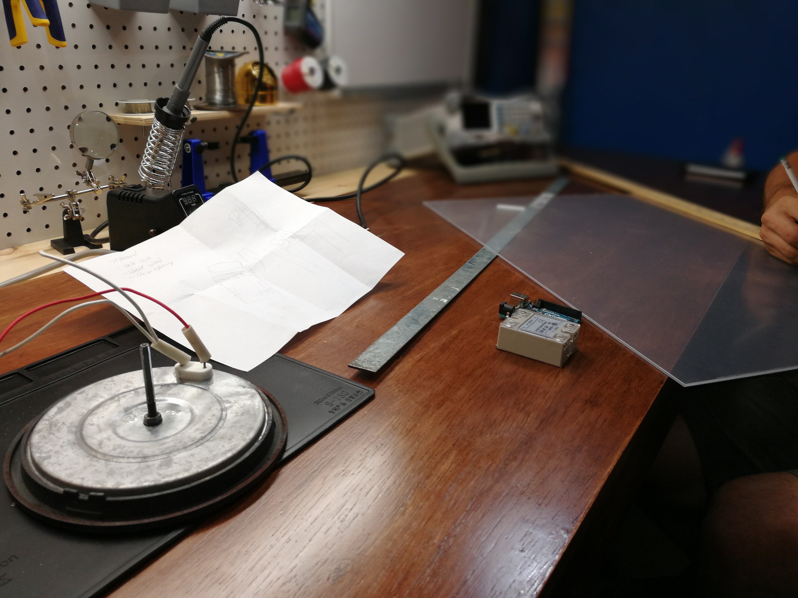
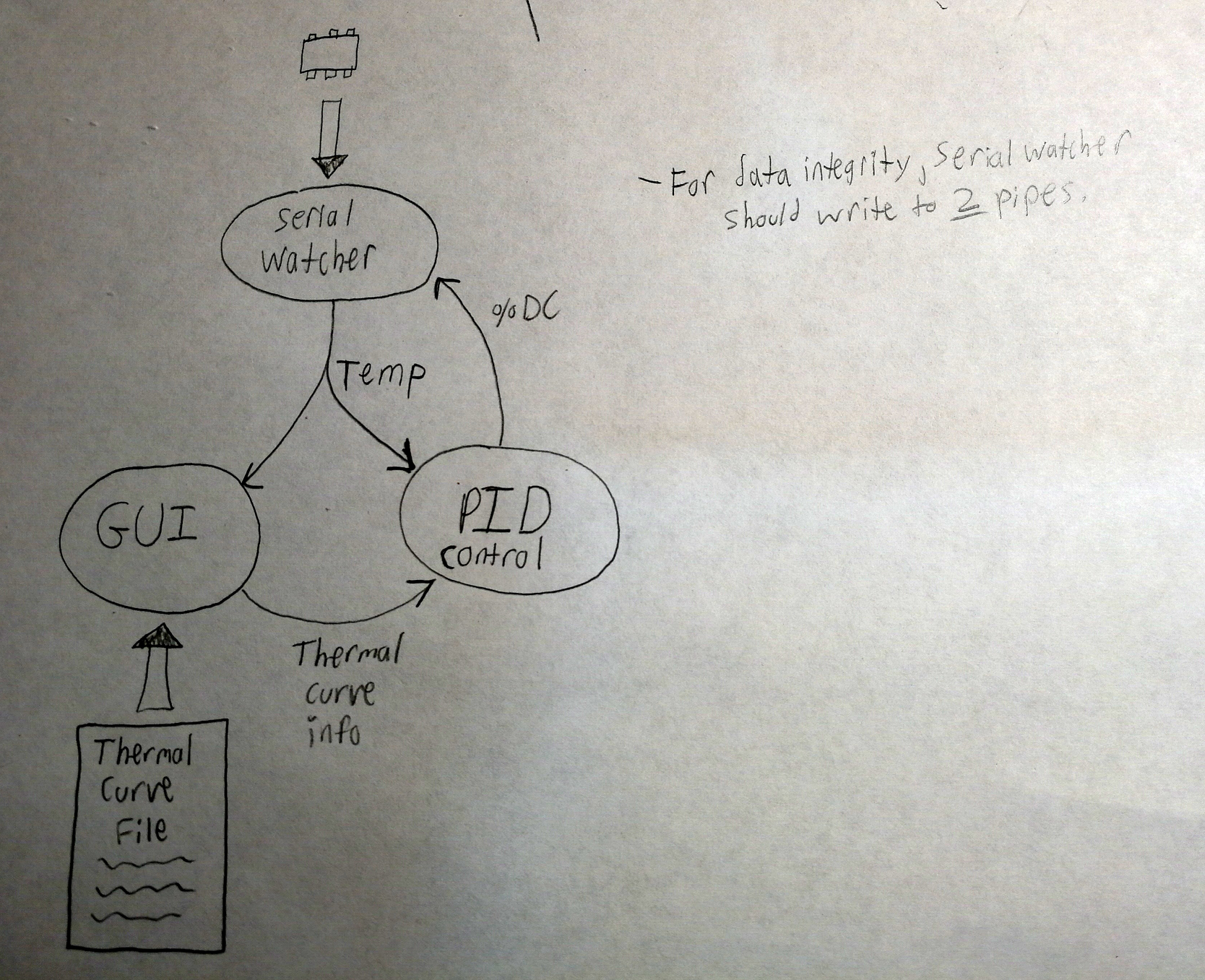
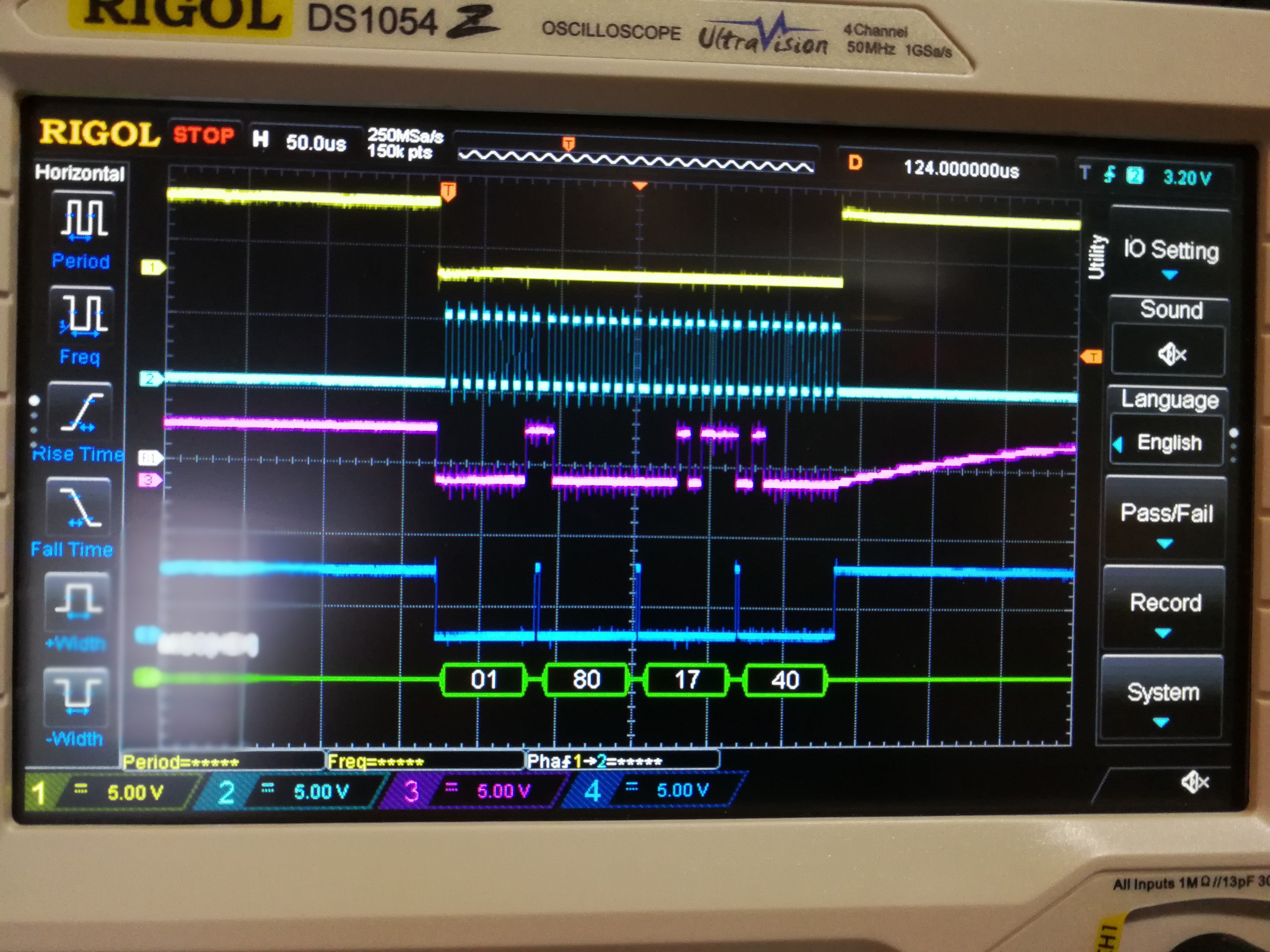
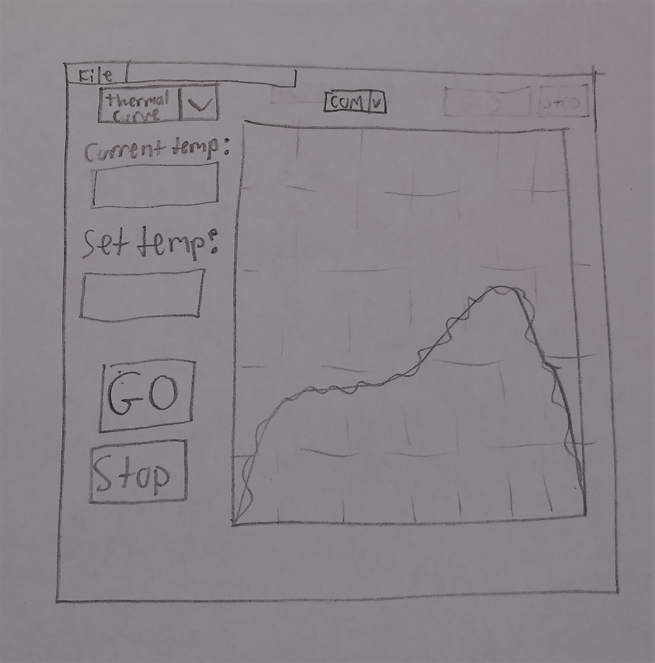
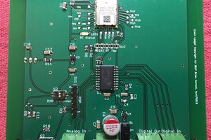
The plan is to use a small AVR microcontroller (ATtiny14?), K-type thermocouple with an Adafruit MAX31855 breakout board, an SSR, and a Python GUI linked to the ucontroller to have a stable temperature controlled hot plate that can have programmable temperature curves to match the solder paste/components to be soldered.


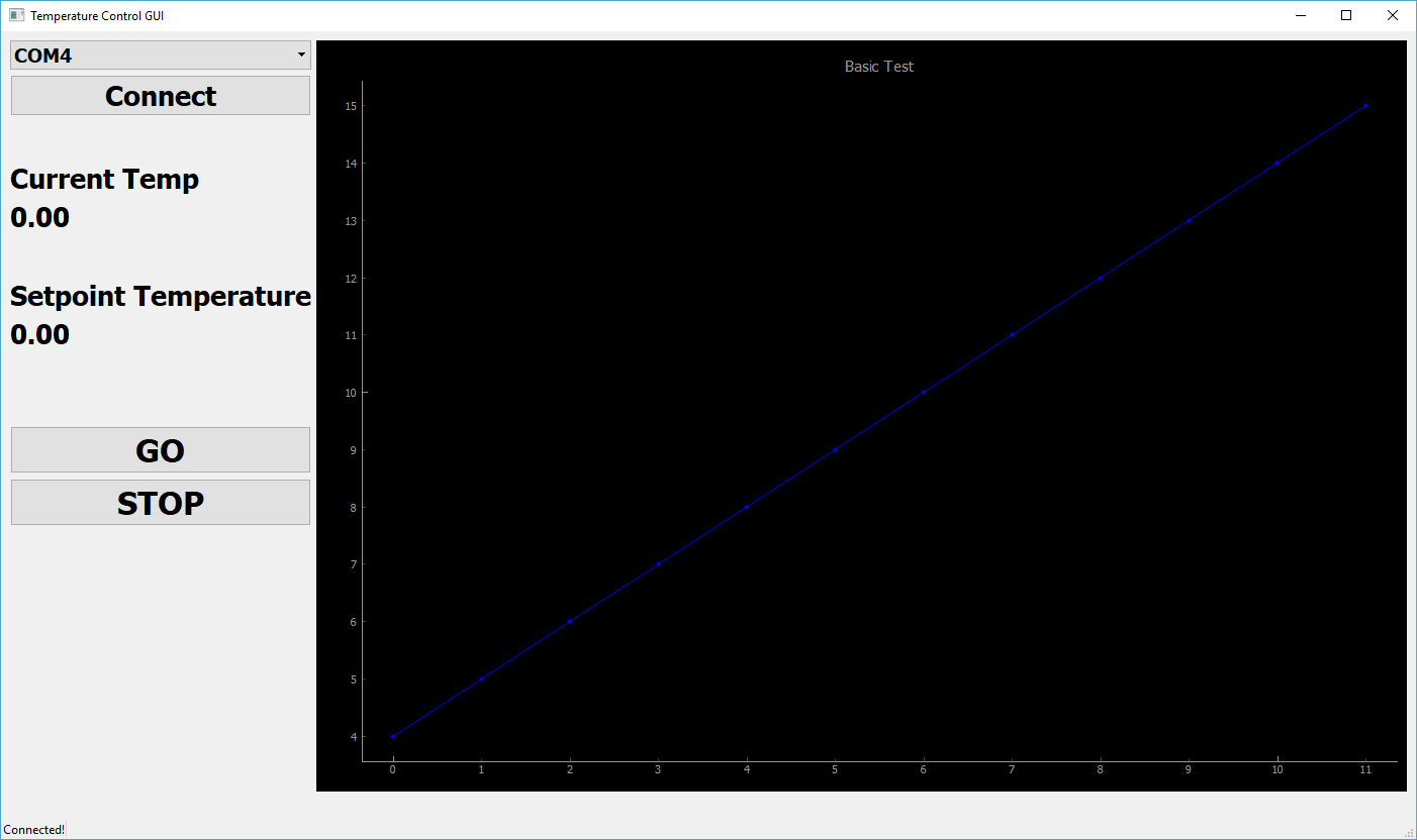
One thing that I think will be different in this project from other DIY reflow hotplates I've seen is that there will be no interface on the reflow oven itself - all the control and brains will be in the GUI on the PC. The ucontroller will really just turn on and off the SSR and read back temperature to the GUI, along with some safety fallbacks such as shutting down the system if things start getting to hot, ucontroller loses communication with the GUI, etc.

The reason behind not having an interface in the oven is several fold. A) I just don't want to deal with buying, soldering and interface programming to an LCD and various buttons. I kind of want this project to be quick and this is my way of doing that. B) I've been interested in getting better at GUI programming and thread programming. This could be a very very basic introduction to those concepts. C) From what I've seen offloading the temperature curve handling to a PC will allow for much diverse and easy selection of thermal curves and profiles. Want to switch over and perform a chemical reaction that needs exact temperature following? Well the idea is you could simply load up a different CSV file and go, rather than tinkering with two buttons for 10 minutes. It remains to be seen if such complex temperature profiles will ever be needed of course...

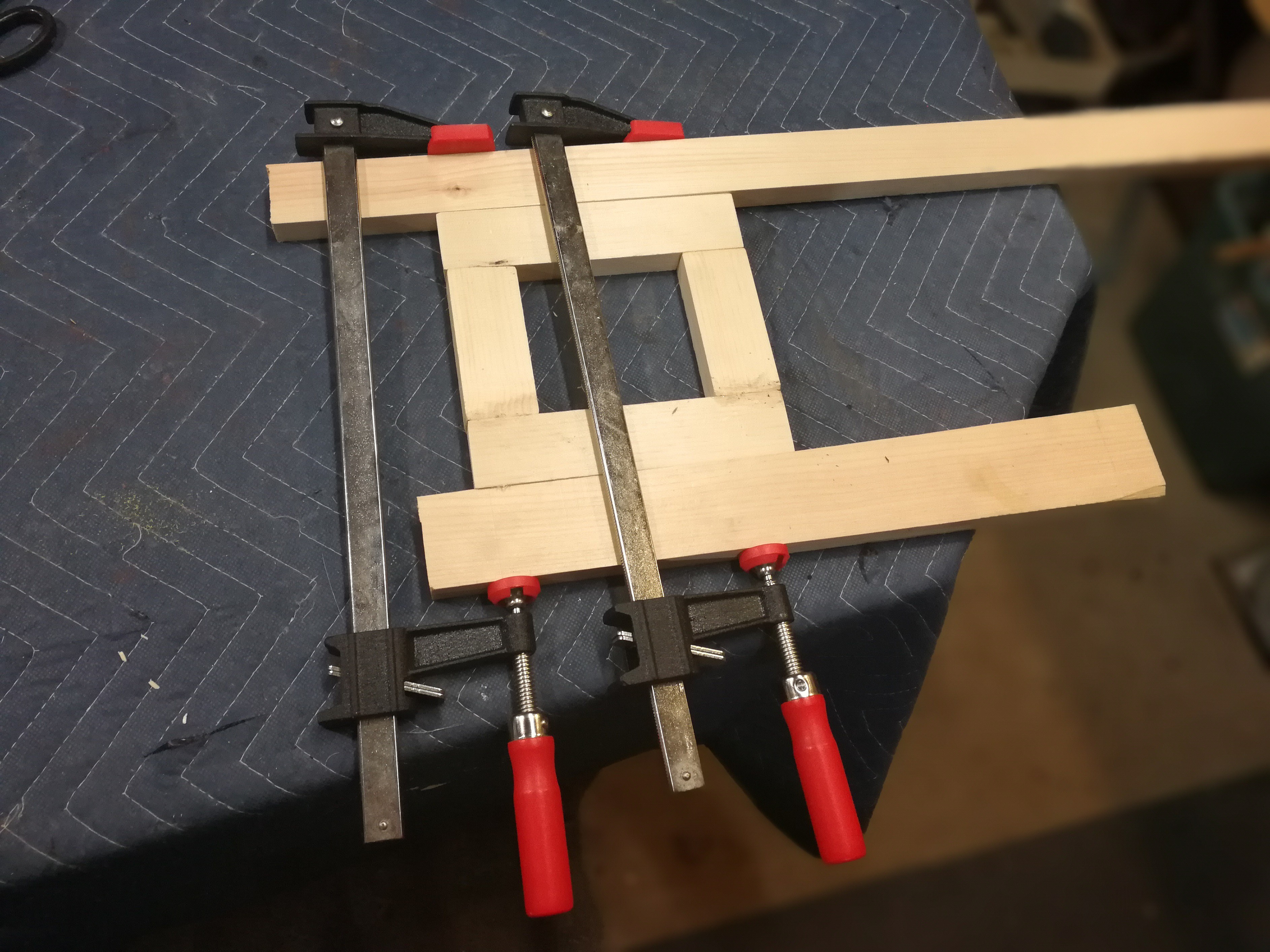
Hopefully the end result will be a cheap and versatile temperature controlled hot plate that can mainly be used to reflow small PCBs for projects at home.

  • 1 × FarberWare Electric Hot Plate Or any hot plate really. I like the ones with circular 'pucks.' They are self contained and durable. The one I got is 900W, plenty of heat output.
  • 1 × SSR-40 DA A solid state relay from Sparkfun that claims a 40A rating for 120VAC. Doubtful of that, but I only really need 7.5 amps.

  • Python Program Progress and Starting Heater Contruction

    Matt Dombroski07/16/2017 at 23:19 0 comments

    The Python side of the project is coming along, with the GUI now able to reliably receive Temperature updates from the µC and plot them in real-time using pyqtgraph. So far the themocouple seems accurate and it is very responsive. I get a 0.25 °C resolution and what seems to be +- 2 or 3 degree accuracy. Overall the MAX31855 has proven to be a pretty reliable thermocouple unit.

    For the µC code I have made UART receive interrupt driven and non-blocking so that everything operates more smoothly and there are less bind-ups. The UART receive works by serving an ISR each time a new byte is put into the UART data register on the ATMEGA328p. The ISR puts the byte into a large buffer that is expected to be larger than any anticipated message and then checks if the received character is a newline. If so it raises a global flag saying that a new string is ready to service by the main program logic, and it is read on the next main() loop iteration. This is definitely not the most robust solution, given the buffer could be overflowed, the termination character may not be a newline given some circumstances, etc. I am debating on adding a circular buffer instead of a linear buffer to stop potential overflows. For termination watching I may expand the set of characters it recognizes as termination indicators, such as carriage return and tab for example.

    For sending temperature data the main loop is delayed every iteration by a set number of milliseconds, at the moment 250 ms. This more or less sets a constant output rate of temp data. Given that temperature control for such a large thermal mass as a 900W heating element isn't particularly fast, extremely precise timing control is not necessary. As long as messages get to where they need to go within about a second, I should be happy.

    One interesting bug I found while programming is that Python multiprocess Pipes seem to need a consumer using the .recv() function to work properly. Ie. if data is being put into the Pipe and not being read, this will go wrong eventually. I discovered this when testing the temperature plotting. I would have 150 sample be plotted, then everything would stop. The program would still be connected to the µC and receiving bytes off the serial port, but they wouldn't go from there to other parts of the program. I finally localized the issue to the where the program put data into the Pipe - the write() function would start blocking after 150 samples and not complete. Putting something on the other end and calling recv() solved the problem. As long as data flows into and then fairly quickly out of the PIpe everything works fine. Perhaps something I will read up more on.

    Changing gears from software, I also began work on the actual enclosure for the hot plate. At the moment the plan is to have a wooden inner frame made from 1x2" pine covered in Plexiglas for walls. The whole thing will be a 7x7x7" cube with the heating puck sticking from the top. In addition the top of the cube, but below the heating puck will be a thin piece of metal plate to act as a heat shield and also for a cleaner look. biggest challenges right now are how to get a fan mounted onto the side of the unit and how to provide access through the plexiglas for an AC plug and a micro USB connector. I do not really have the tooling for plexiglas so cutting a slot or such will be difficult. I have half a mind of raising the cube another inch and just dropping cables through the center and out a side. More details on the frame construction will come in future logs.

    In the meantime here are some photos of the frame construction:

    Measuring plexiglas cuts.

    Cutting the plexiglas with good old razor blades.

    Crude and fairly dangerous, but a really fast way of getting all the edges to be equal.

    So this will be a reference of what the bottom and top wooden frames will look like. Having just pulled this from the clamps I realized I didn't quite make sure everything was flat and true, so it has a horrible...

    Read more »

  • SPI success and Better GUI

    Matt Dombroski07/14/2017 at 01:55 0 comments

    In the past few days I've gotten more progress down with the GUI, finally sitting down and figuring out a data flow pattern for the different parts of the PC based program. The overall architecture consists of three programs running concurrently - a serial watcher process that handles UART communication with the µC, a PID/control process which takes in data from the serial watcher and the GUI and figures out what the µC should be doing in terms of heater element duty cycle and the optional fan state. Then the GUI process which handles the user input and file i/o for the temperature curves (those details of which are still being worked out). A diagram is shown below of the rough idea of how the program will talk to itself and the world:

    The GUI itself got a good face lift, now juust starting to begin to look like a usable program. I also hooked it up with pyqtgraph for realtime graphing of serial data from the µC. It so far works a charm, just want to play around with the colors a little bit. Definitely if you want an easy to use quick-and-dirty and most of all fast plotter to use in python, I don't think you can beat pyqtgraph. There are a lot of features built in without needing a lot of your attention and the overall use is intuitive. It also comes with some superb example scripts that give you all the groundwork you could want. Without further ado, here is the GUI:

    In addition to the PC side, I finally cracked the SPI bus problem I was having and got data rolling from the max31855thermocouple amplifier. A big part of getting this to work was the Rigol DS1054z oscilloscope that I just received yesterday. An excellent scope for the price, and it includes a demo (and permanently hackable) SPI decoding feature. The problem was the SS pin on the Arduino was not falling fast enough to trigger the MAX31855 chip select pin and have it start listening when the arduino started clocking in data. I cut the small RST_EN trace thats a bit below the RX LED but maybe I didn't cut it completely enough, the SS pin still takes a good amount of time to fall and the trace looks identical to a capacitor discharge. Kind of a weird thing I found in addition to this though is that it would seem you need to use the SS pin for selecting a slave or the SPI module won't start clocking data. I switched to a different IO pin for CS select instead but then didn't have any clock pulses. Re-enabling the SS pin and I got clock pulses again. Perhaps this would be something to investigate more if one wanted to get really deep into the functionality of the ATMEGA328p. At the moment my solution is to toggle both the SS pin and have it go nowhere, and also toggle another IO pin which is actually connected to the MAX31855 CS pin. Ugly but is working a charm. And just because, here is a picture of the scope with SPI traces and some decoded data:

    Probably look to the weekend for some more updates and hopefully more results!

  • Python GUI

    Matt Dombroski07/07/2017 at 01:40 0 comments

    I've temporarily put the µC coding on hold due to problems with the SPI coding which I will get back to - so more details on the µC side later. In the meantime I have started coding the Python GUI for controlling the heater - in reality this is the meat of the program as the Python program will be computing the PID outputs and really doing all the heavy lifting.

    For the GUI itself I am using PyQt5. The planned layout will perhaps look like something below (apologies for hand written diagram...) :

    I already have a super basic window ready to go:

    While underwhelming visually underneath the hood I have most of the groundwork ready for the program. For kicks I am using the multiprocessing() library to branch my program into a few different processes running concurrently. One process talks to the µC over a serial port, putting messages from the µC to a Queue and taking messages the PID wants to send from another Queue and sending them over the serial port. The PID runs in another process, receiving messages from the serial process and processing them into a new PID duty cycle output. It will also generate any other messages and processing necessary to control the hotplate. I really shouldn't be calling this process 'PID', controller would be more apt. Maybe I will change that in the code soon. Finally the GUI runs in a process showing the data and commands being sent around and getting user input, along with controlling the overall state of the system.

    Hopefully over the weekend I will get more time to develop the GUI into something more fleshed out.

    In addition, I just received an ATEMEL-ICE debugger. Hopefully this will give me a more in-depth look into what is going on inside the SPI bus.

  • Heating Element

    Matt Dombroski07/05/2017 at 01:23 0 comments

    This is a retroactive post. I have already obtained heating element for the hot plate. It comes from a $30 FarberWare hot plate that I got a few years ago when I was into chemistry projects. It has two circular puck elements of different sizes. I took the larger one out of the unit and did some basic measurements for heating time. From 150 C to 220 C it can heat at or above a 1 degree C per second rate, which is pretty ideal for solder reflow during the actual reflow stage. It's also about 8" in diameter which should be sufficient for fairly large PCBs (at least for what I'll be making).

    In addition I have already started on the microcontroller code for the project. For this project instead of using basic Arduino libraries I decided to go with register level programming. First time I have done this with AVR chips and am doing it simply for the experience. The requirements for the ucontroller code are as follows:

    • Send data over UART port to PC including:
      • Temperature data - which comes in 32-bit packets
    • Receive UART data from PC including
      • PWM duty cycle for driving the SSR
      • (optional) Duty cycle for a cooling fan to quickly cool the system down
    • 16-bit PWM driver on Timer1 (for ATMEGA238P) for low frequency PWM (~1Hz) to the SSR
    • (Optional) PWM channel for the fan
    • SPI communication to the MAX31855 to read the temperature of the hot plate from K-type thermocouple
    • Safety fallbacks including:
      • Watchdog timer on UART communication - if no new command after a few seconds shut down the system until communication re-established

    So far I have the UART communication down and low frequency PWM for the SSR. I am currently working on SPI communication to the MAX31855 which is so far proving difficult. Mostly because I do not have a logic analyzer so I have no clear idea about what bits are actually being sent around on the system.

    I will have code posted soon on Github.

View all 4 project logs

Enjoy this project?

Share

Discussions

Similar Projects

Does this project spark your interest?

Become a member to follow this project and never miss any updates