 Matt Dombroski
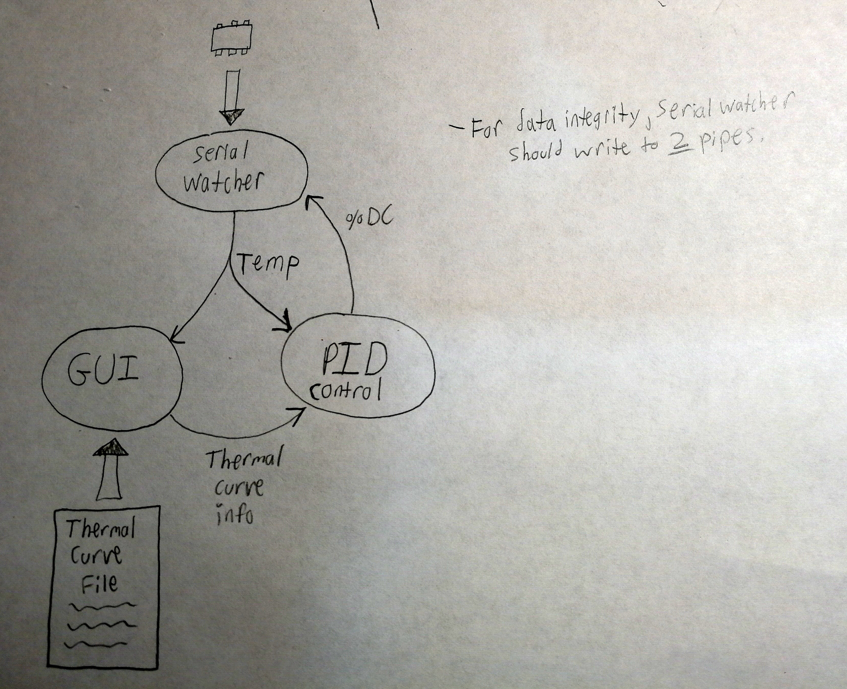
In the past few days I've gotten more progress down with the GUI, finally sitting down and figuring out a data flow pattern for the different parts of the PC based program. The overall architecture consists of three programs running concurrently - a serial watcher process that handles UART communication with the µC, a PID/control process which takes in data from the serial watcher and the GUI and figures out what the µC should be doing in terms of heater element duty cycle and the optional fan state. Then the GUI process which handles the user input and file i/o for the temperature curves (those details of which are still being worked out). A diagram is shown below of the rough idea of how the program will talk to itself and the world:
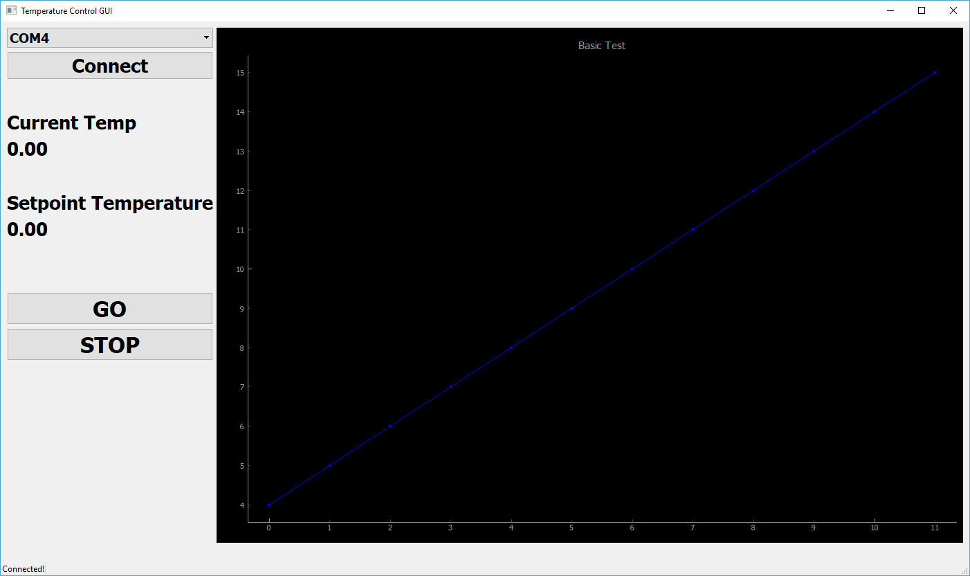
The GUI itself got a good face lift, now juust starting to begin to look like a usable program. I also hooked it up with pyqtgraph for realtime graphing of serial data from the µC. It so far works a charm, just want to play around with the colors a little bit. Definitely if you want an easy to use quick-and-dirty and most of all fast plotter to use in python, I don't think you can beat pyqtgraph. There are a lot of features built in without needing a lot of your attention and the overall use is intuitive. It also comes with some superb example scripts that give you all the groundwork you could want. Without further ado, here is the GUI:
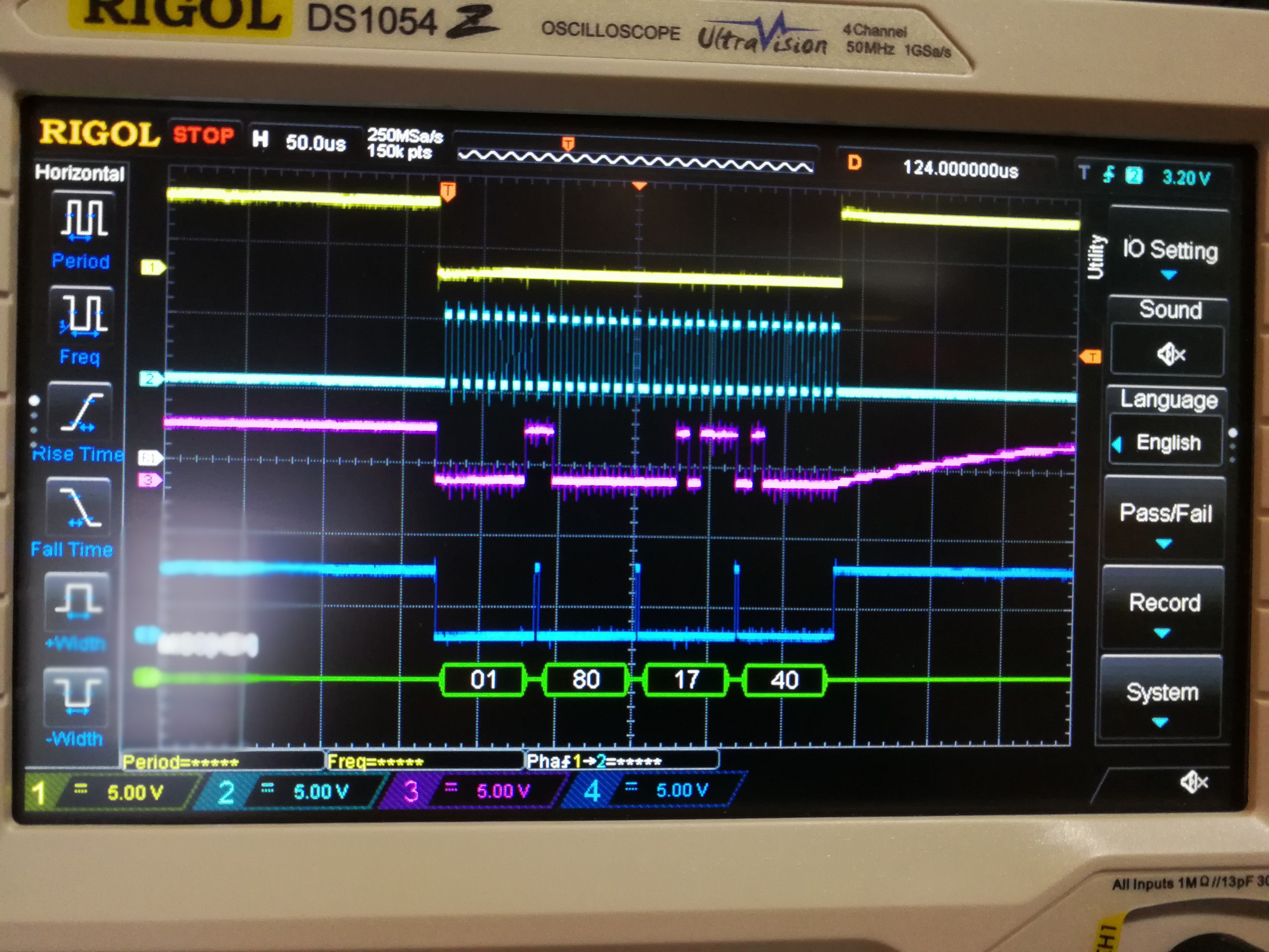
In addition to the PC side, I finally cracked the SPI bus problem I was having and got data rolling from the max31855thermocouple amplifier. A big part of getting this to work was the Rigol DS1054z oscilloscope that I just received yesterday. An excellent scope for the price, and it includes a demo (and permanently hackable) SPI decoding feature. The problem was the SS pin on the Arduino was not falling fast enough to trigger the MAX31855 chip select pin and have it start listening when the arduino started clocking in data. I cut the small RST_EN trace thats a bit below the RX LED but maybe I didn't cut it completely enough, the SS pin still takes a good amount of time to fall and the trace looks identical to a capacitor discharge. Kind of a weird thing I found in addition to this though is that it would seem you need to use the SS pin for selecting a slave or the SPI module won't start clocking data. I switched to a different IO pin for CS select instead but then didn't have any clock pulses. Re-enabling the SS pin and I got clock pulses again. Perhaps this would be something to investigate more if one wanted to get really deep into the functionality of the ATMEGA328p. At the moment my solution is to toggle both the SS pin and have it go nowhere, and also toggle another IO pin which is actually connected to the MAX31855 CS pin. Ugly but is working a charm. And just because, here is a picture of the scope with SPI traces and some decoded data:
Discussions
Become a Hackaday.io Member
Create an account to leave a comment. Already have an account? Log In.