 Bud Bennett
This is a completed project.
The HX711 has all of the necessary components to process the output of a velocity sensor: 24-bit resolution with nominal sample rates of either 80Hz or 10Hz, a programmable gain pre-amplifier with gain values of 32, 64 and 128, and a fully differential bridge-type interface. I ordered a pre-built module from eBay for about $1. After a few hours of “tinkering” with it I realized it’s potential as a seismometer interface, but I had to toss out the eBay module to unleash it.
The HX711 datasheet shows an application using its internal/external regulator to provide a quiet analog supply for the ADC. It also says that if the on-chip regulator option is not used, the two supply pins can be connected to a separate regulated supply. Using a 3.3V LDO regulator is a better option for use with the Pi because the Pi GPIO interfaces operate at 3.3V. The HX711 supply range is specified over 2.6V - 5.5V.
I also found that the HX711 internal clock generator was more than 20% low on the eBay board. This may be why it only costs a buck. This is not really acceptable for a seismometer — the seedlink server software is a bit sensitive to variable sampling rates. But the HX711 provides for a crystal controlled clock (not an option on the eBay board, which is hard-wired at the slow sample rate.)
The HX711 ADC requires its inputs to both be within a certain common mode range but the eBay board did not provide any circuitry to accomplish that.
Lastly, the HX711 has a weird serial communication protocol that requires a bit-bang on two GPIO pins. The HX711 is designed to go into a low-power sleep mode if the PD_SCK input goes high for more than 50µs. This is a difficult requirement for the Raspberry Pi because of the Linux housekeeping. There is a HX711 interface for Python, using PIGPIO, but it kept quitting after a few seconds or minutes of operation. I suspect that eventually the Raspian kernel would clobber the code and it stops for some reason. I just implemented a 1µs one-shot to control the PD_SCK input, which prevents the HX711 from sleeping and solved a lot of the interface issues -- sometimes software can’t fix everything. Since the one-shot frees the code from having to keep the PD_SCK high time less than 50us I can limp along with the generic GPIO interface. Every once in a while the data is clobbered by the kernel, but I have a pulse swallower that detects this condition and just sticks the previous “good” data into the current sample and proceeds merrily along. I can get away with this because the system is oversampled by 10x. Since a seismometer requires 24/7 operation the sleep function is not required or desired.
So here’s the final schematic for a seismometer velocity sensor:
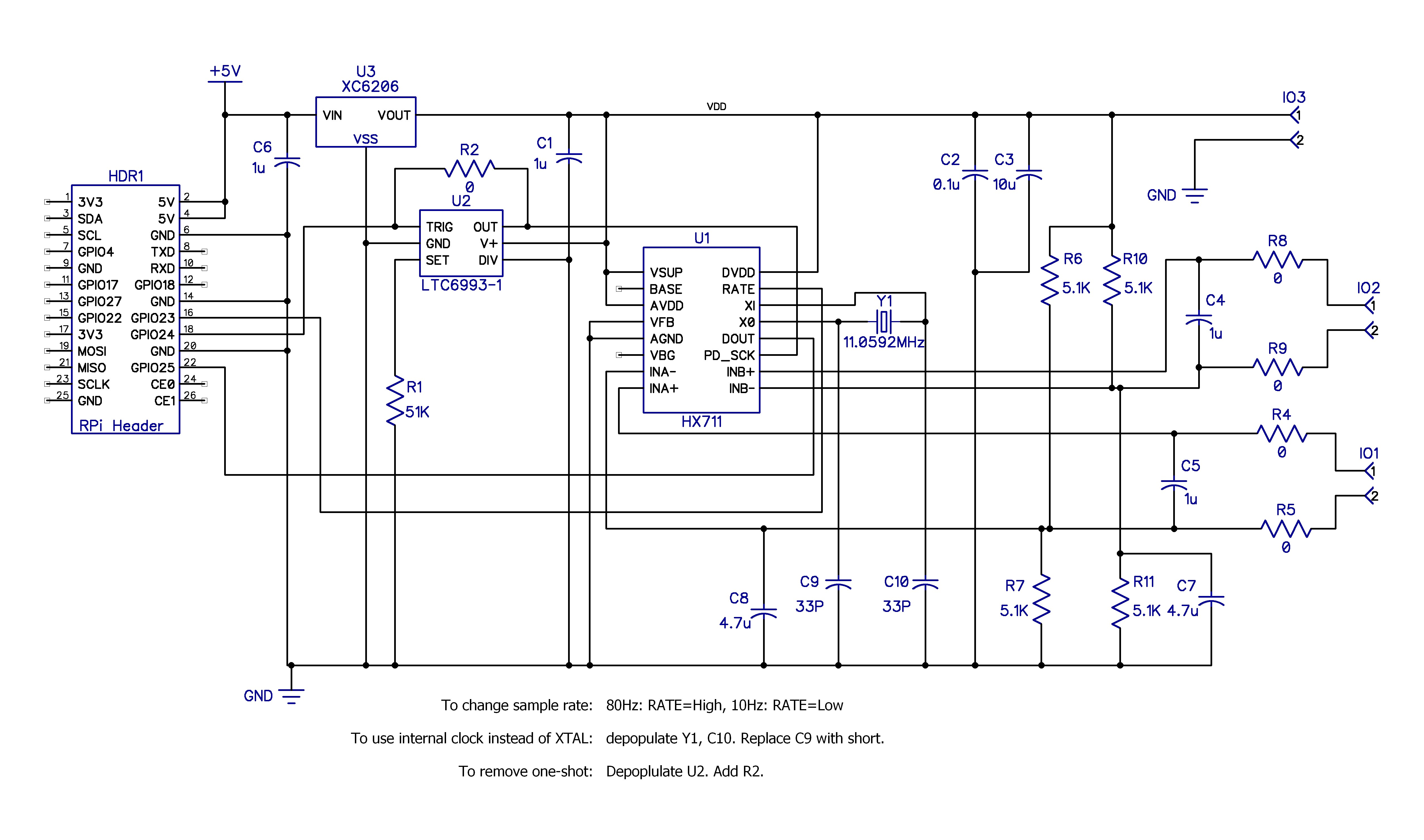
U3 is a cheap ($0.06) LDO regulator that puts out 3.3V +/- 2% and is stable with small ceramic capacitors. All of the circuitry operates from the 3.3V VDD and makes the digital interface to the Raspberry Pi much easier.
U2 is a 1µs one-shot. It prevents the PD_SCK pin from ever setting the HX711 into sleep mode. The one shot can be removed from the board and R2 (a short) can be used to directly connect the Pi to the HX711, if desired. This is a much cheaper solution, since the LTC6993-1 is the most expensive component by far at $3.35 in low quantities. But it is a cute part and provides a low component count solution to the sleeping HX711 problem.
The Pi can set the sample rate to Fcrystal/138240 or Fcrystal/1105920, which yields 80Hz or 10Hz when using a 11.0592MHz crystal. The HX711 is specified to function with crystal frequencies from 1MHz to 20MHz. You can also configure the board to use the HX711 internal oscillator if desired. I found the 80Hz rate a bit too fast for a seismometer application: it generates a large amount of data storage per day and the RPi has problems keeping up. So I am using a 4MHz crystal to get a sample rate of about 29Hz with the RATE pin set high.
The rest of circuitry is signal conditioning and can be modified for the application. R6/R7 and R10/R11 bias the inputs in the middle of the supply range -- the sweet spot for the HX711. If you are using a bridge sensor then hang it between VDD and the input terminal blocks and depopulate R6/R7 or R10/R11 depending upon which channel you use.
The PCB is custom from OSH Park — $5.50 for three prototypes (shipped). Total BOM/board comes to about $7 (~$3.50 without the LTC6993) after sprinkling in nine 0603 resistors and ten 0805 capacitors, $0.50 for a 26-pin female header, and $0.10 for a crystal from Tayda Electronics. Everything is surface mounted except the header and the crystal. Yes, it's more than the $1 for the eBay board, but it's a much cleaner solution that offers more customization that plugs right onto the Raspberry Pi header.
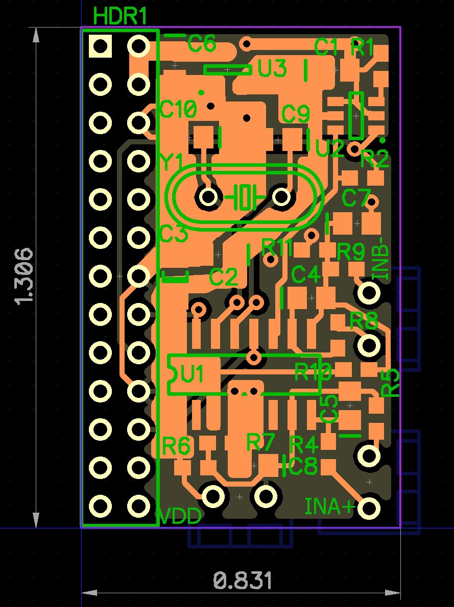
There is not much that I can say about the layout. I attempted to keep all of the sensitive analog stuff at the bottom of the board and put the XTAL, one-shot, and LDO near the top -- as far away from the analog as possible. I think that it is possible to hand-solder the layout, but it might be pretty ugly, depending upon your soldering skill. I use a hot-air rework station for all of the surface mount soldering. The header and the three terminal blocks are mounted on the bottom side. It saves a lot of board area to have the terminal blocks underneath. For my application, I only need one terminal block for INA since I don't require channel B or VDD for the sensor.