 WJCarpenter
This is some notes and pictures for how I finally decided to stack things together with the microprocessor board and the display board. (And the power supply board, but it's not really any kind of issue.)
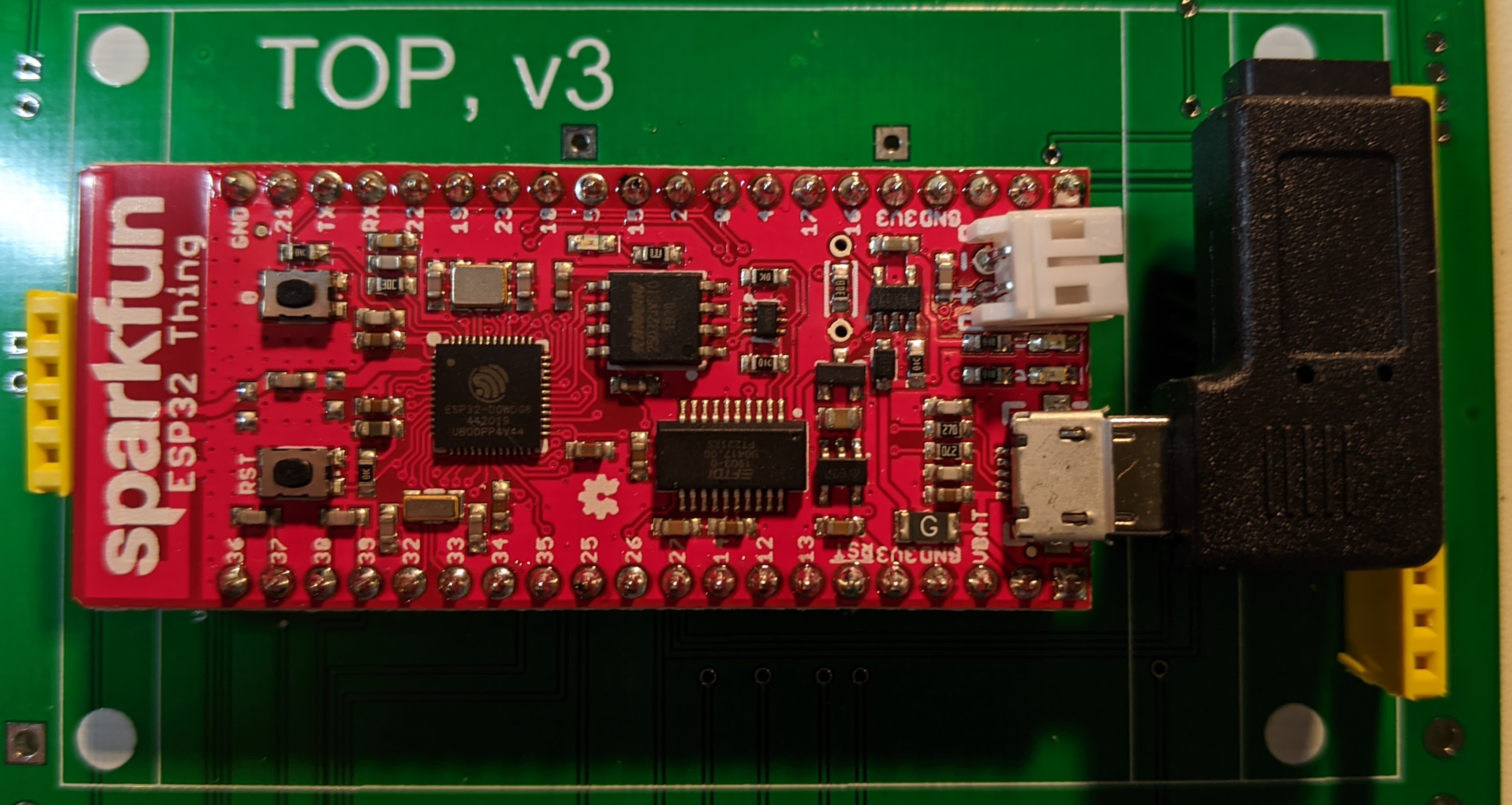
Here is the microprocessor board in place with the header pins soldered on. As a reminder, and as you will see in some later pictures, the header pins are shorter than standard and are inserted into a 40-pin DIP socket that is soldered to the main PCB. You can also see that I left the battery connector intact, and the micro-USB right-angle connector is attached. (It is clear of the yellow connector on the right side, though the angle of the photo creates the illusion that they interfere).
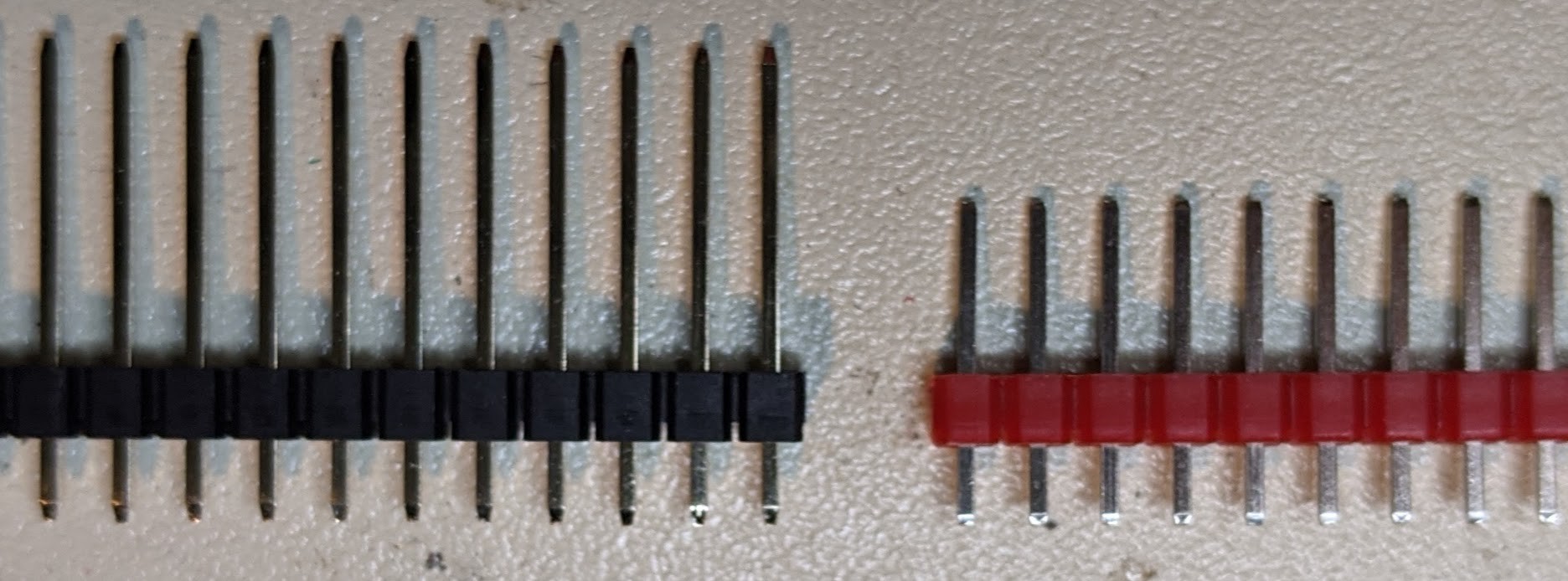
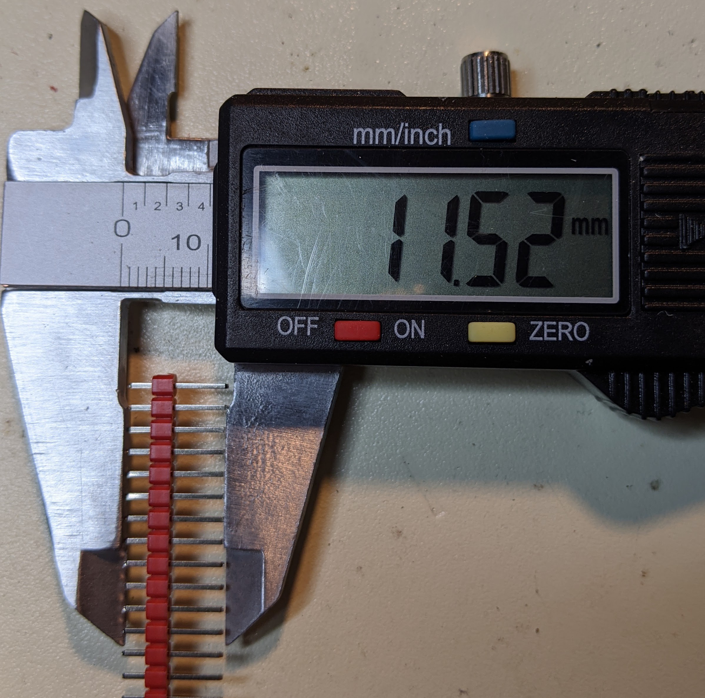
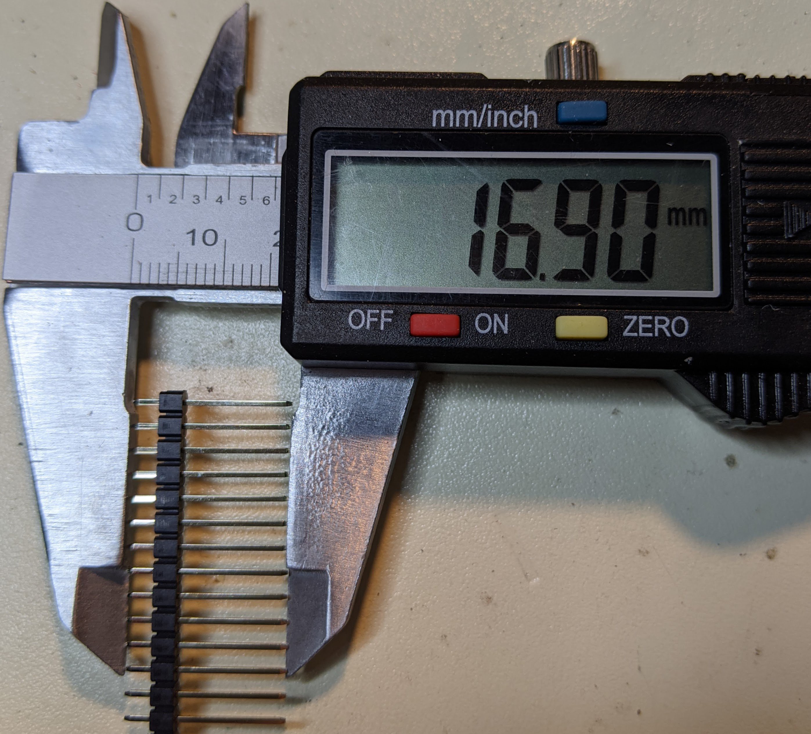
The 17mm male pin headers turned out to be just right for mounting the display board. Here are some photos comparing them to the run-of-the-mill standard male pin headers.
The display board with the 17mm pins mounts with plenty of clearance over the microprocessor board, except that it just barely touches the battery connector. There is a sliver of vertical space between the display board and the micro-USB right-angle connector.
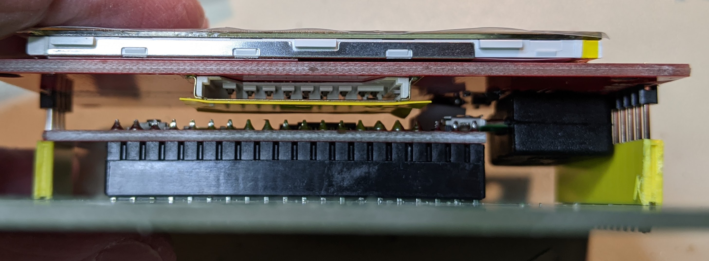
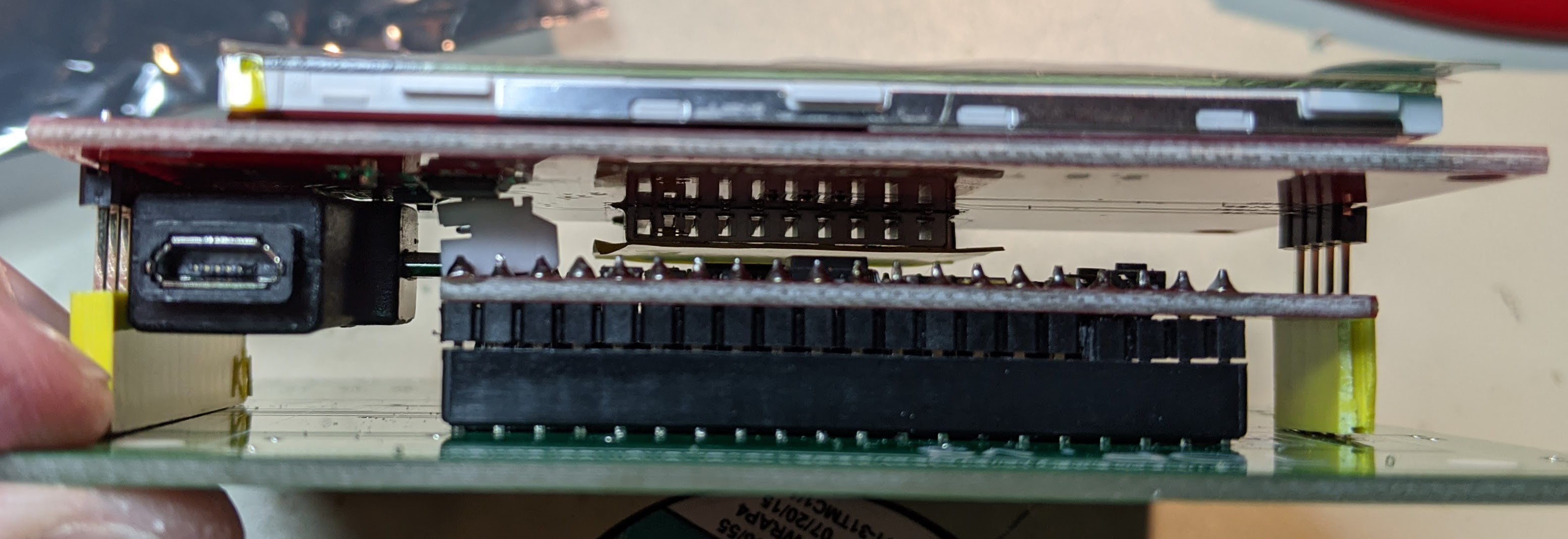
I'm not sure yet, but I guess I will probably remove the battery connector just to avoid future problems. It's easy to remove since it's a right-angle connector. I can just pry it up from the edge of the microprocessor board and either snip the two pins or fatigue them until they snap from bending the connector back and forth.
Here's the back side of the display board with the 17mm pins soldered in place. The display boards came with the 14-pin strip already soldered in place, so I had to remove that first. (If you don't have a good desoldering tool, removing a long header can be a pain. I have such a tool, so it wasn't too bad.)
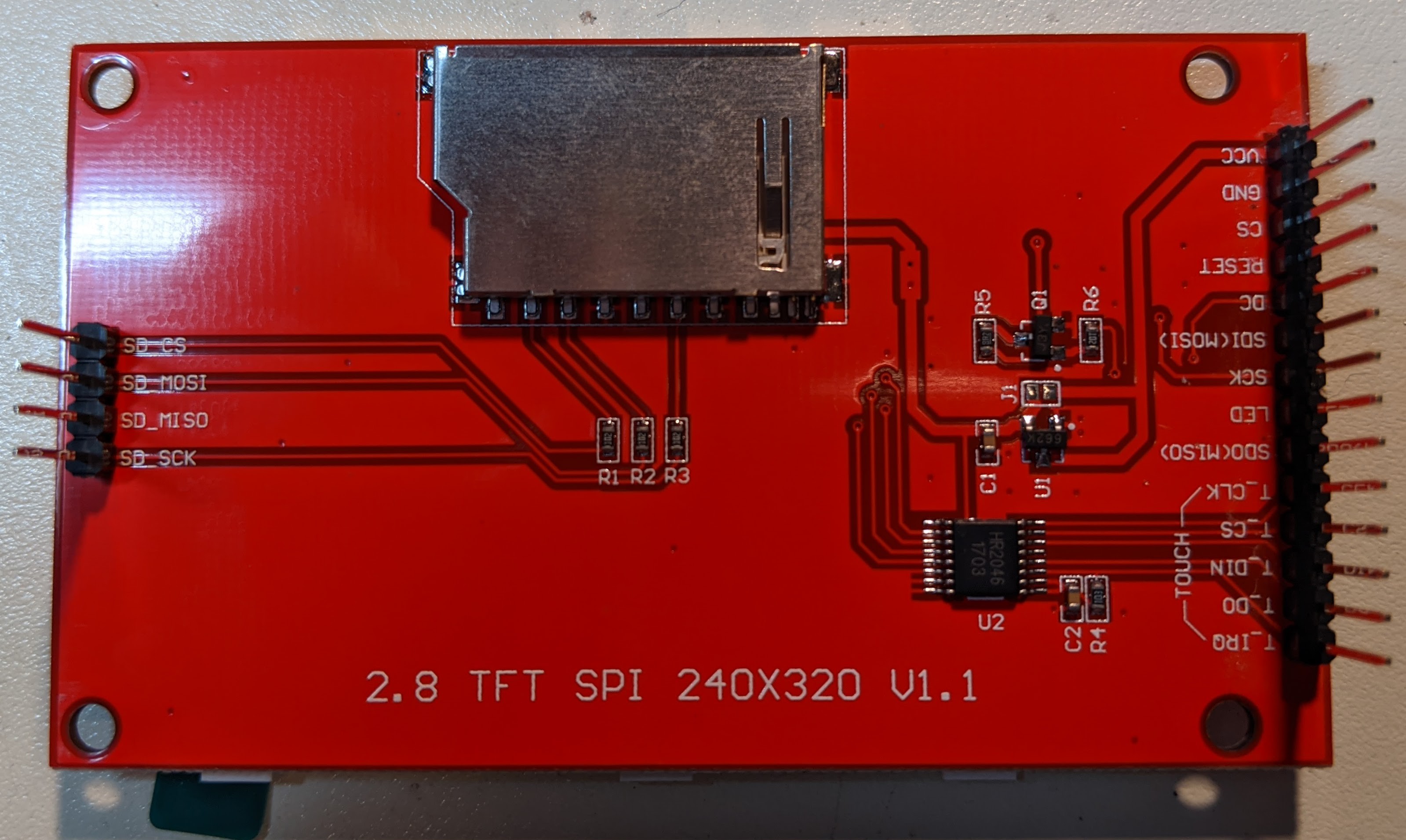
The metal can at the top of the photo is the socket for the SD card. As a precaution, I covered it with (yellow) electrical tape, which you can see in the earlier photos.
I have a few of these display boards, and I noticed that some of them come without the chip at location U2. That's the touchscreen controller chip. I don't know why some of the boards don't have it. I used a board that has it for this project even though I don't think I'll be able to use it due to how I plan to mount the circuit in a box. I just like to have options.
In hindsight, maybe I should have included some stand-off posts in the design, just for physical stability. The positions are shown on the main PCB silkscreen, but I didn't avoid them in the PCB layout.
Discussions
Become a Hackaday.io Member
Create an account to leave a comment. Already have an account? Log In.