 Yann Guidon / YGDES
Logs:
1. References
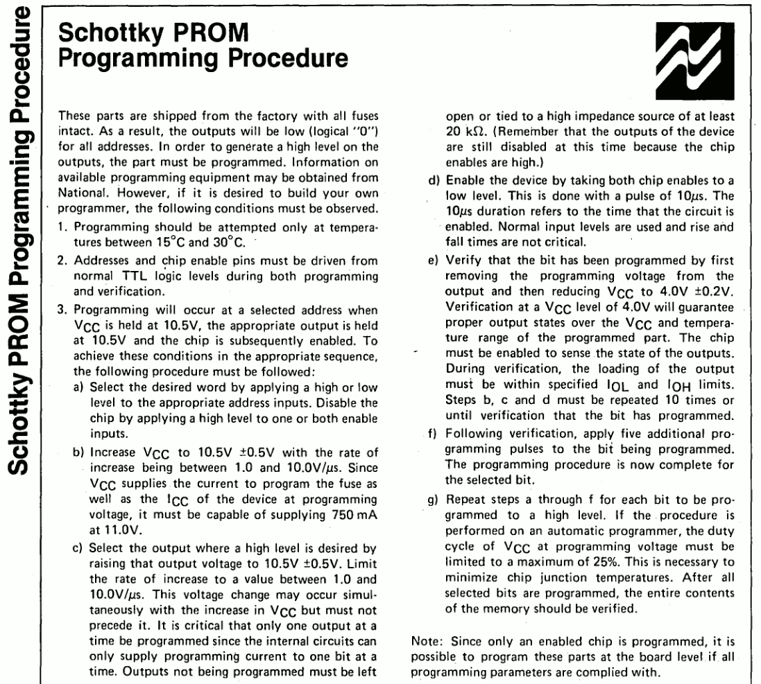
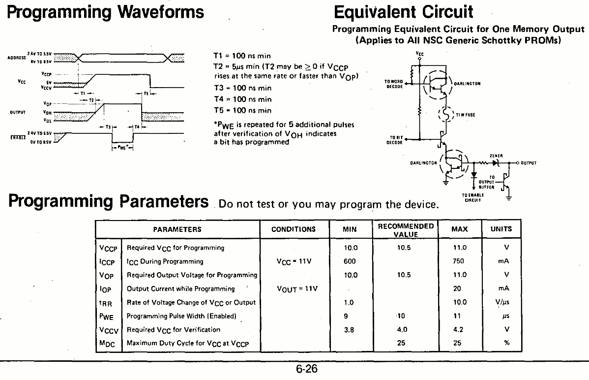
2. First casualties
3. Design considerations
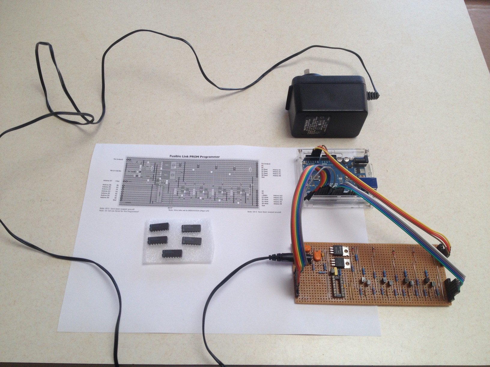
4. Firing up an old PROM Programmer
5. BLANK
Decoding hexadecimal to 7 segments has been a long story, that has been brought back to life with the #Discrete YASEP and gave life to the #PICTIL and #DYPLED ... but it was still not satisfying because they are really modern.
Hexadecimal decoding chips are not easy to find but a smart guy solved this :
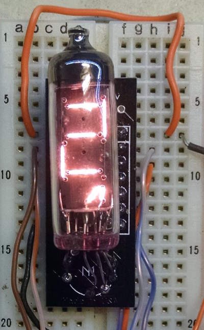
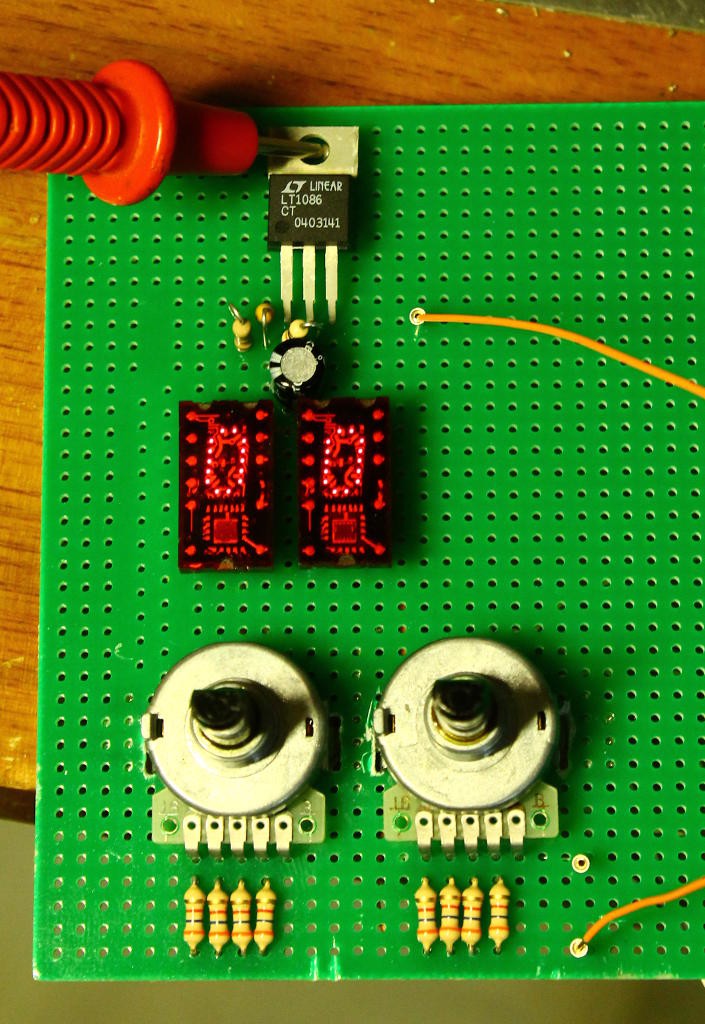
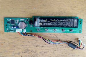
I had been interested in Numitron displays lately and this one gave me a critical hint with one of the pictures:
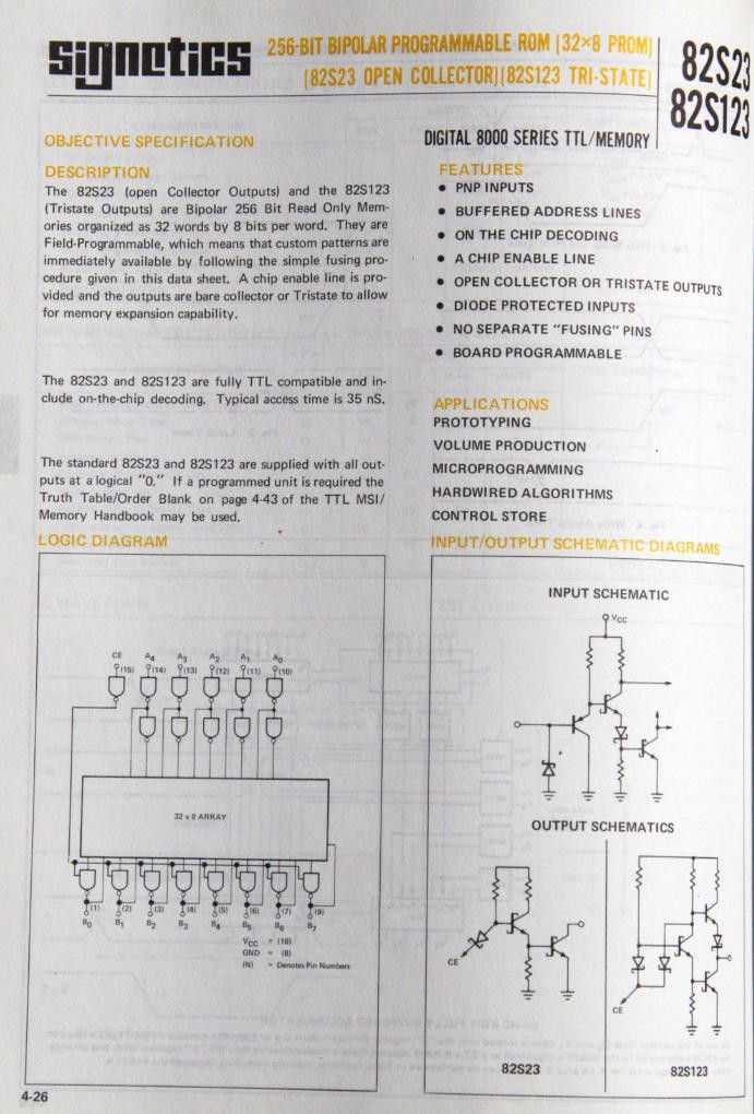
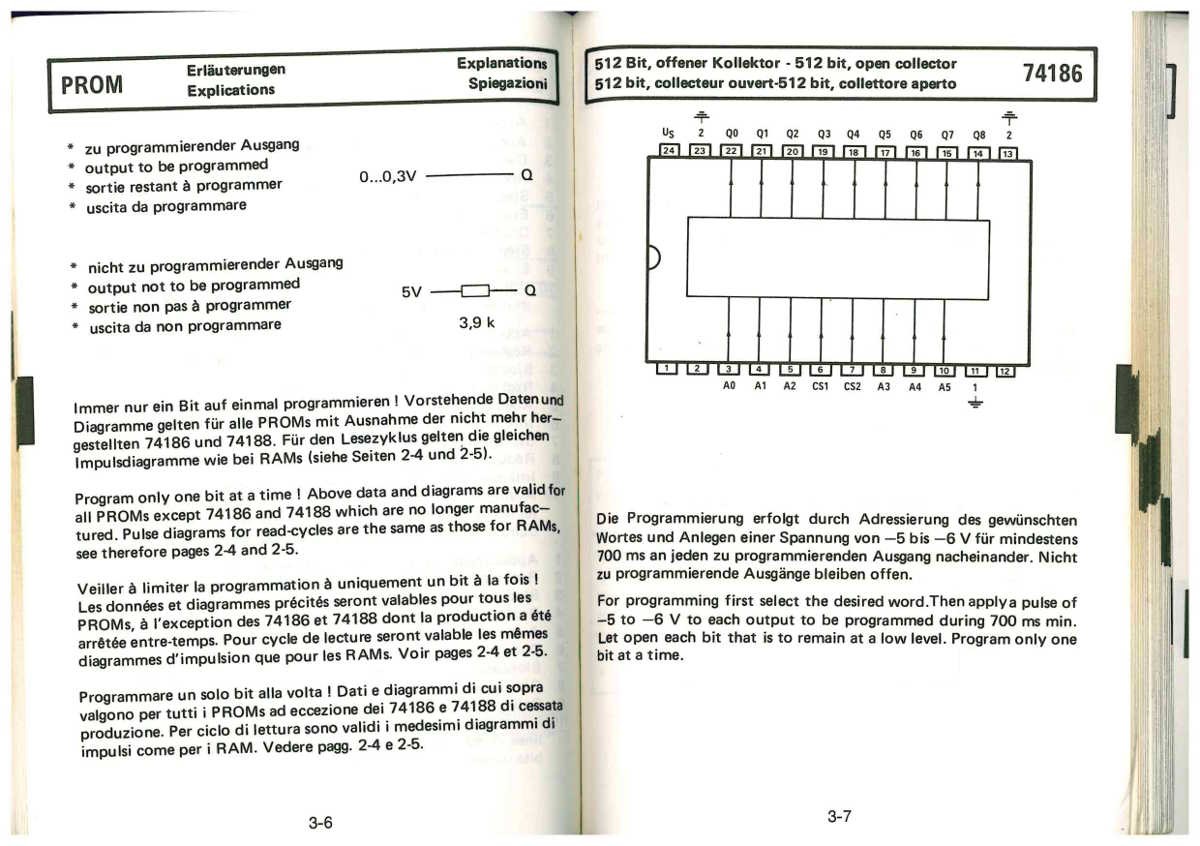
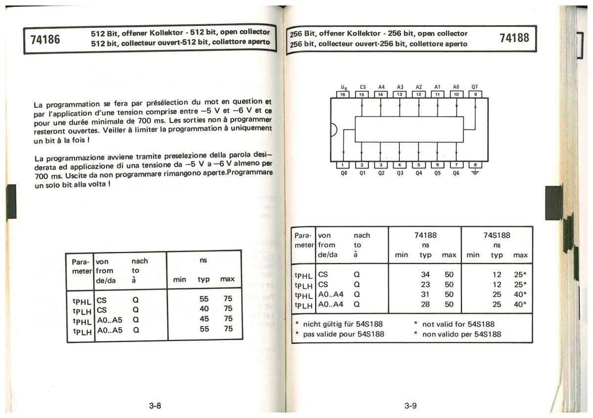
The decoding chip is actually a PROM : the K155RE3 is a Russian equivalent of the SN74188. Each segment draws up to 20mA but can work at a slightly lower current, so this is close to the circuit's limit but still manageable.
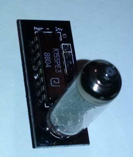
The 5 address lines are enough for a hexadecimal decoder. The extra line could be used for "reverse polarity", as hinted by the jumper labelled by the silk screen "Non-Inv". Another use would be a backup area if the first half contains an error (errare humanum est). No idea how the 8th data bit can be used though. (log 5 says leading-0 cascading)
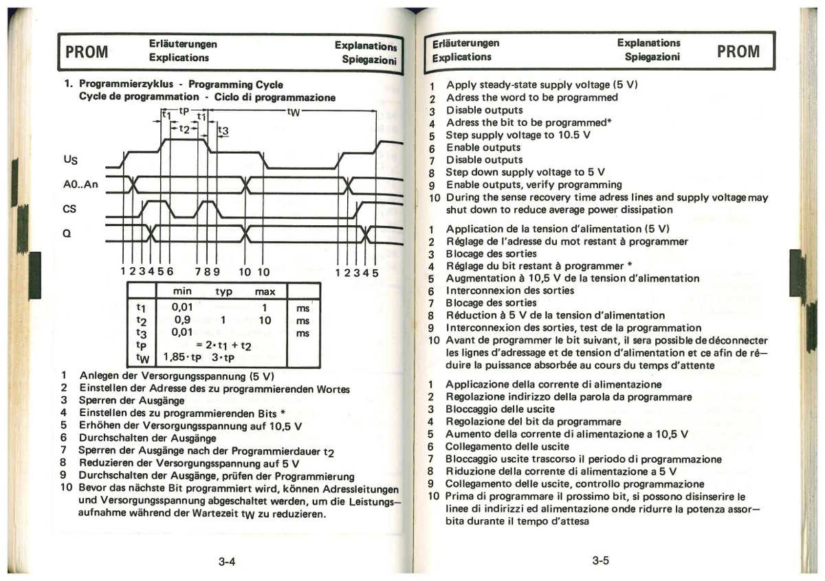
I could find some of these parts AND information about the programming procedure, thanks to several people who did it as well !
One awesome advantage of having custom decoder chips is the ability to extend the "vocabulary" as well as remapping the pins to ease routing of the PCB traces.
Small and fast PROMs are useful for quite a few other purposes, such as small FSM, address decoding, translation of register number (in the #YGRECmos ), so having my own burner is pretty handy. I have a number of PAL22V10 but they are often overkill and it's not easy to generate the JEDEC programming files... My MiniPRO TL866A can flash the PAL but without a JEDEC file, they are quite useless.
.
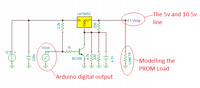
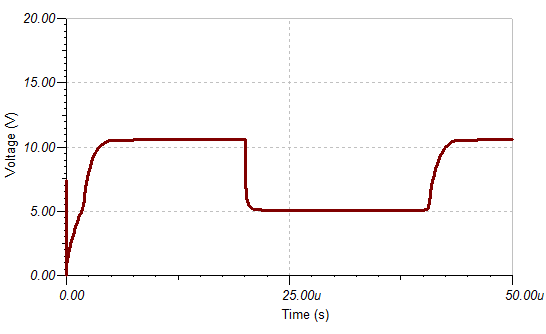
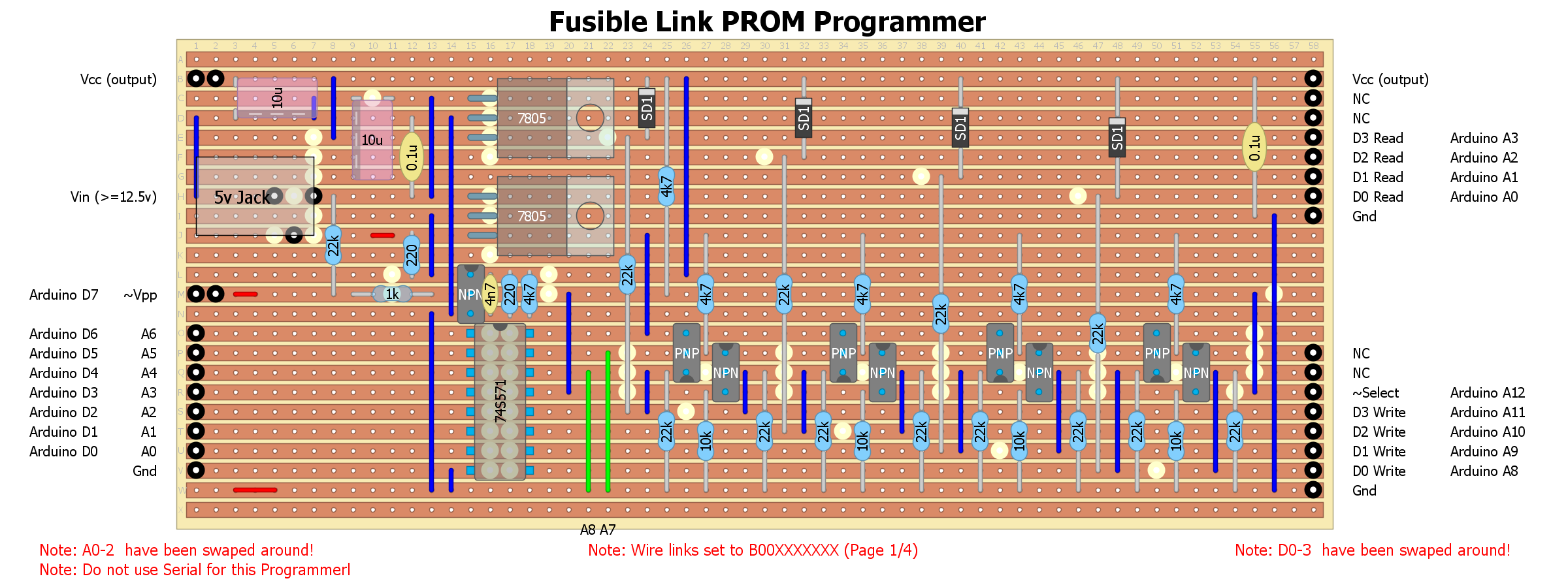

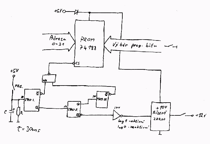
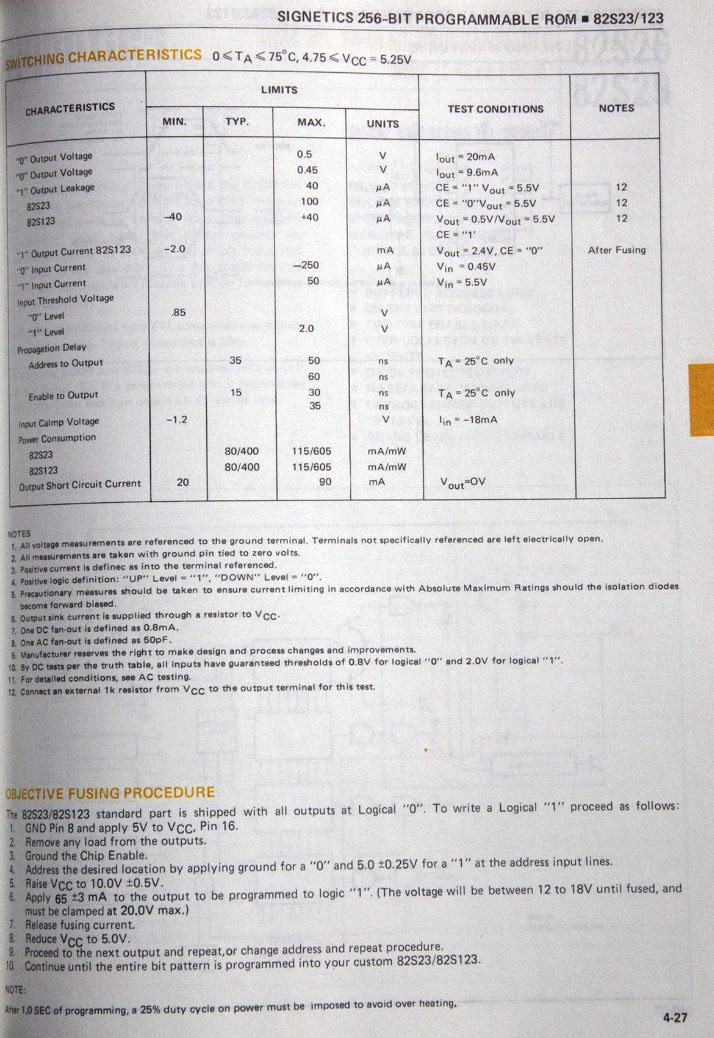
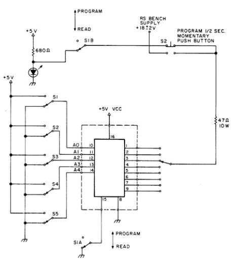
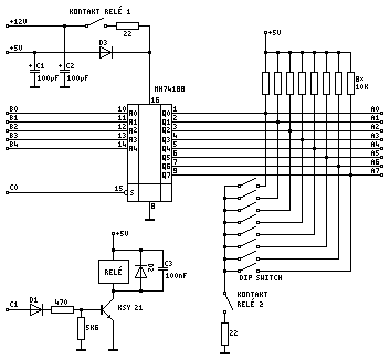
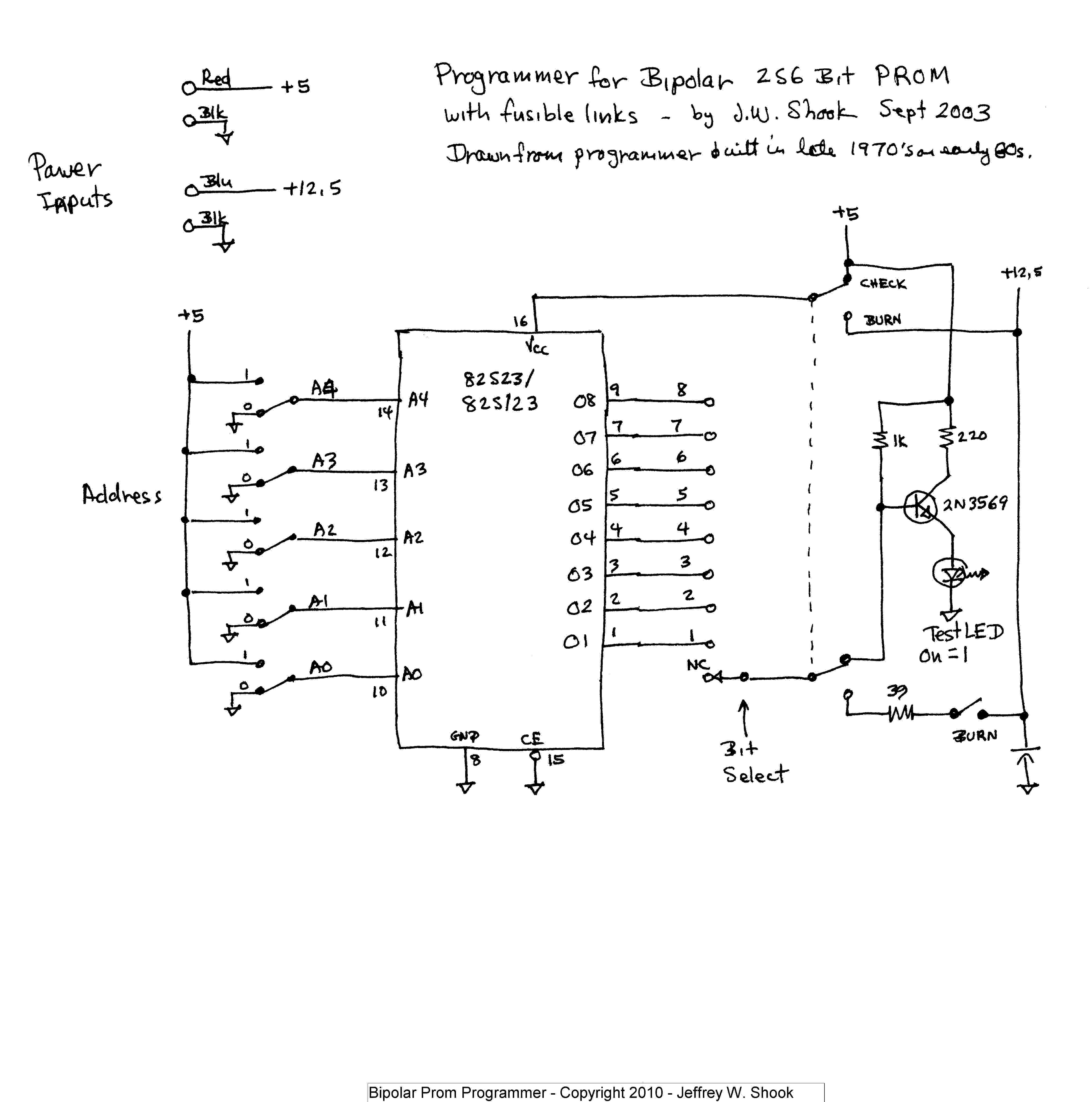 Note: this schematic applies to the 82S23 which has a particular, slower programming cycle, with a 1s pulse, limited to about 65mA (hence the series resistor and the push button), as found at
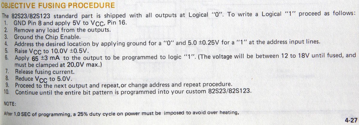
 Lauri Pirttiaho
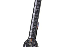
 Florian Baumgartner
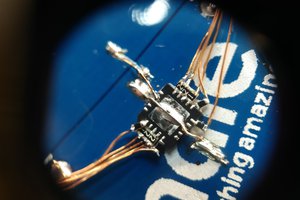
 zakqwy
 Jarrod