 sisam
sisamLicense
All images and linked files are licensed under a Creative Commons Attribution-NonCommercial-ShareAlike 4.0 International License.
Construction
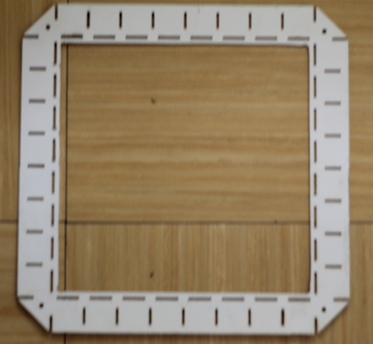
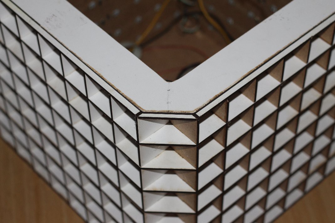
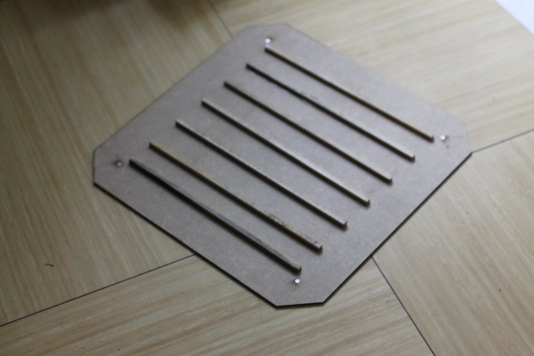
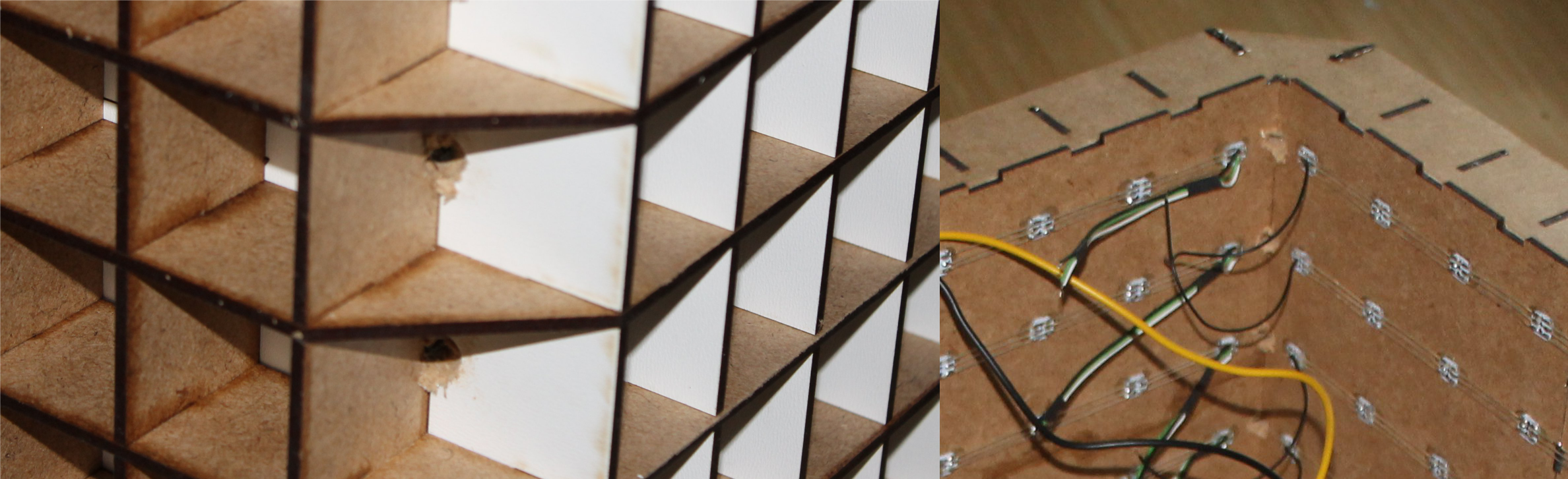
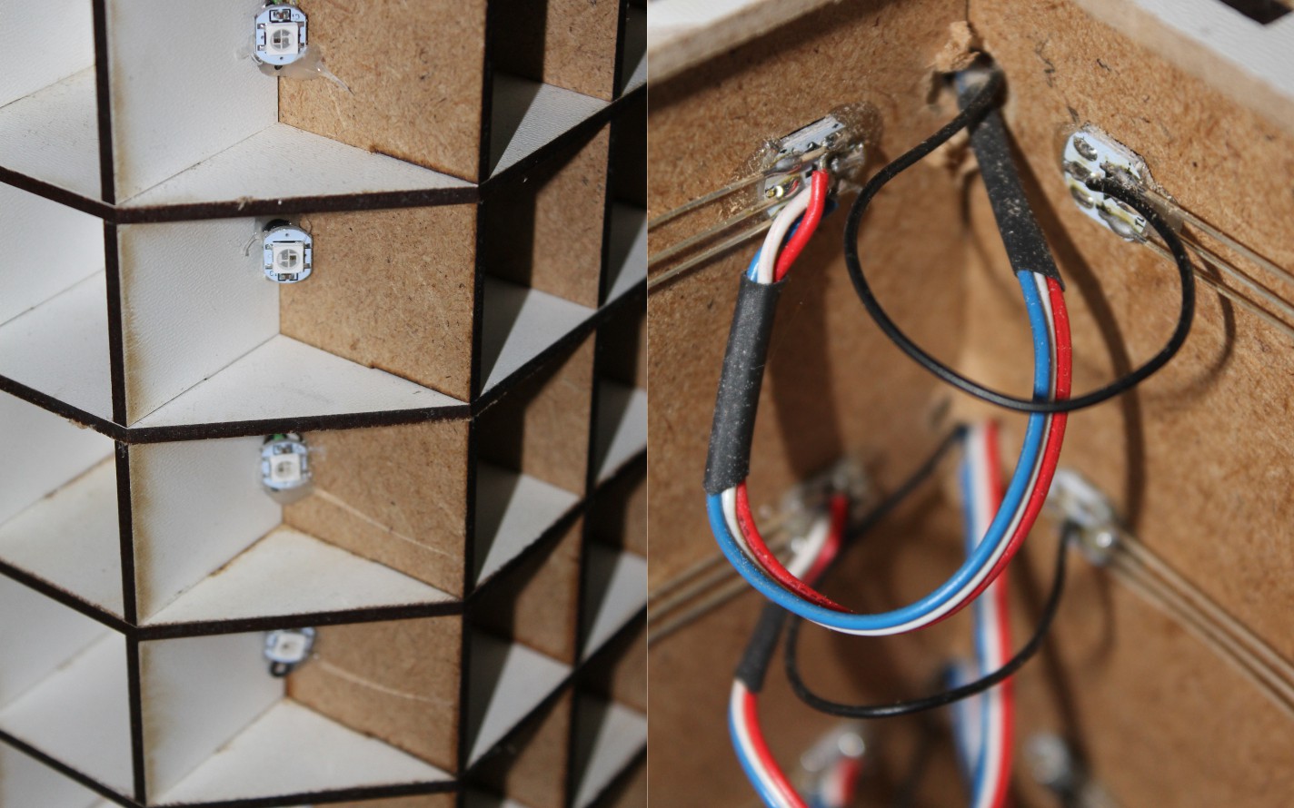
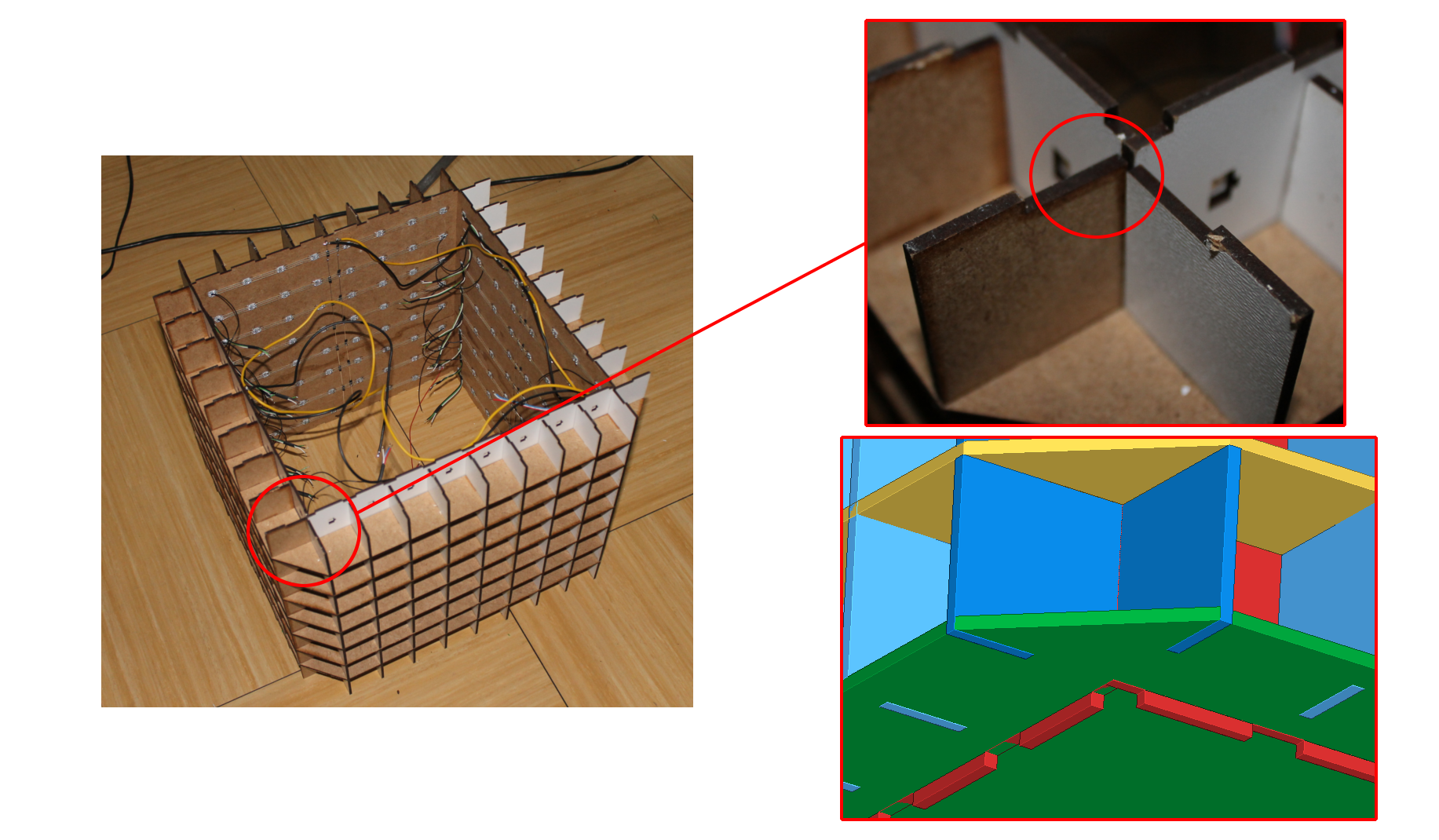
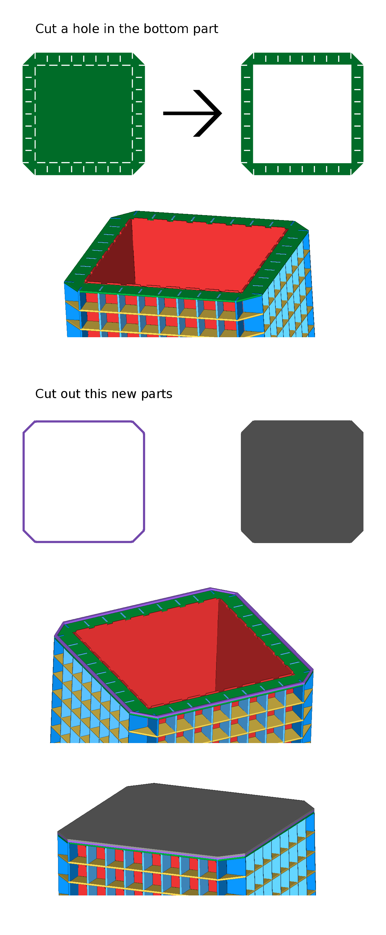
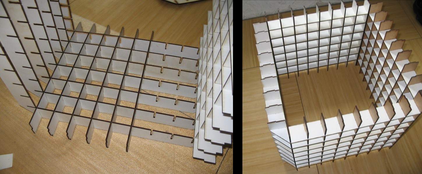
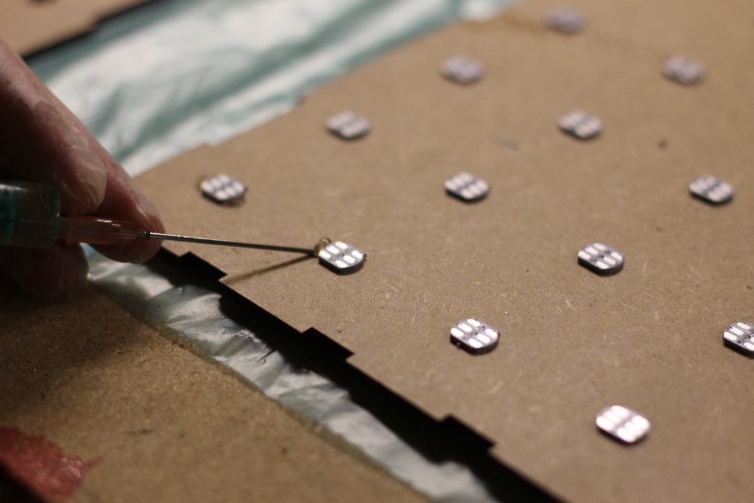
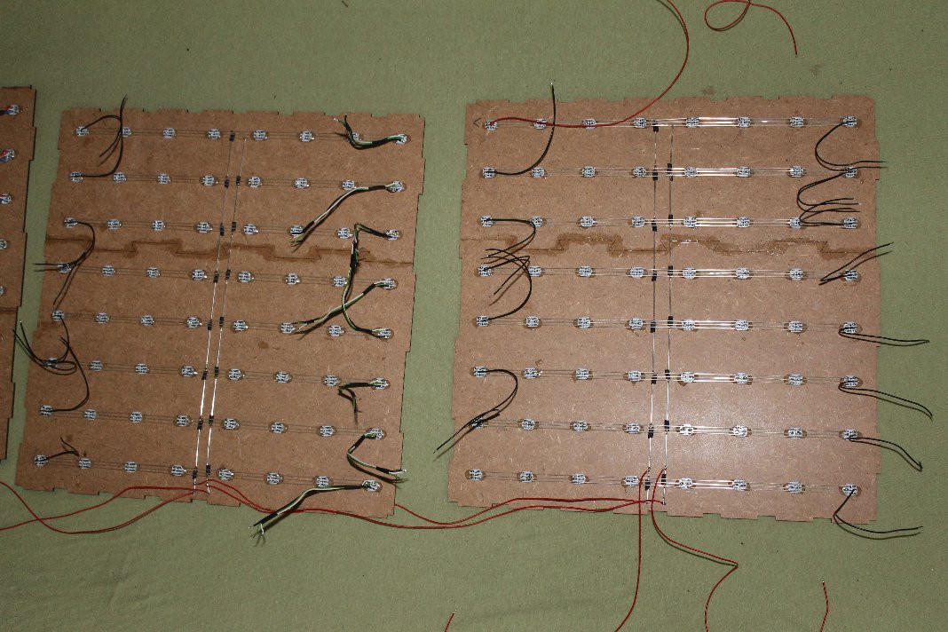
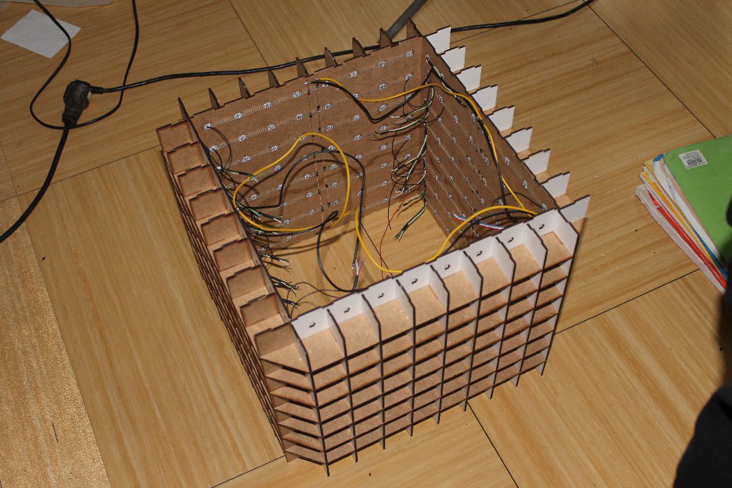
Cube
You can download all parts of the cube ( .dxf ) and a 3D modell ( .step ): here
the endings of the .dxf files ( .._x[numder].dxf ) tells you how often you need that part.
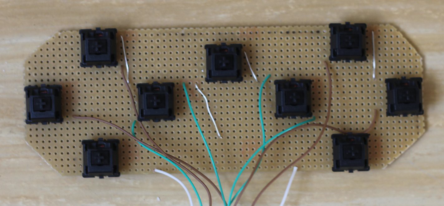
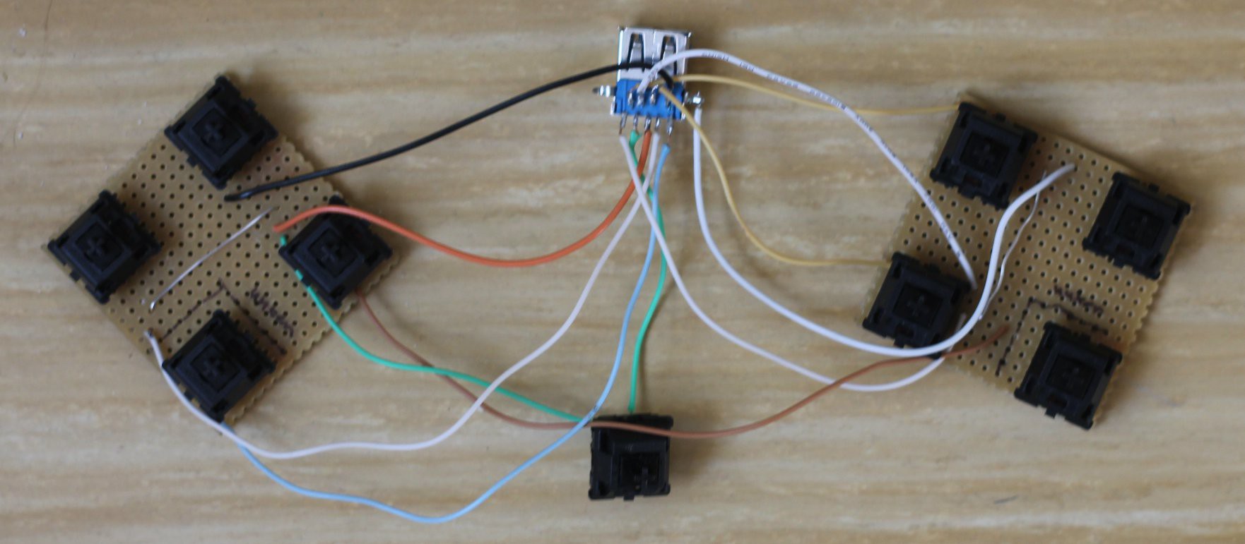
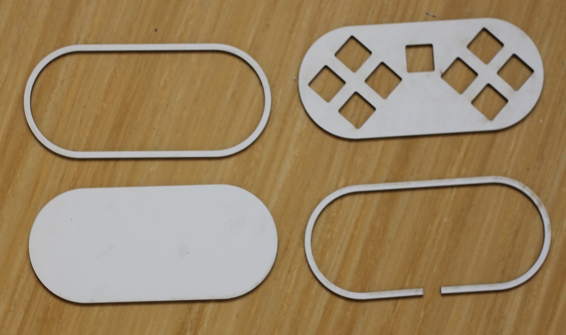
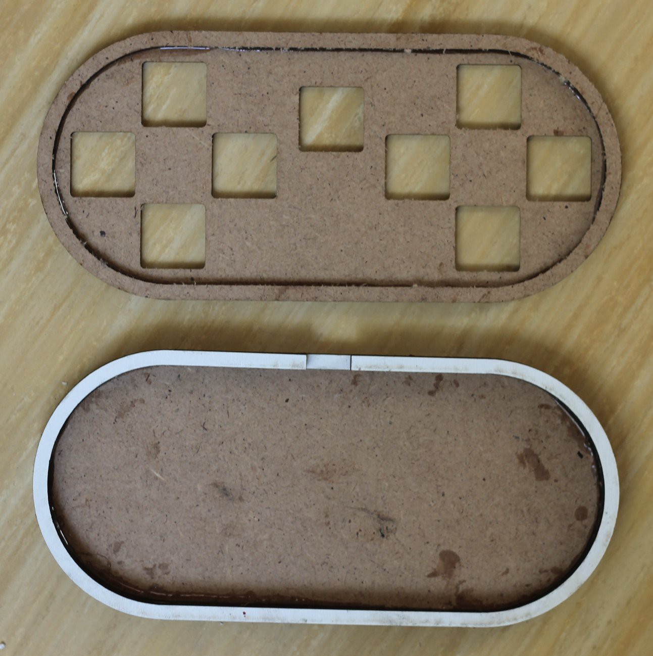
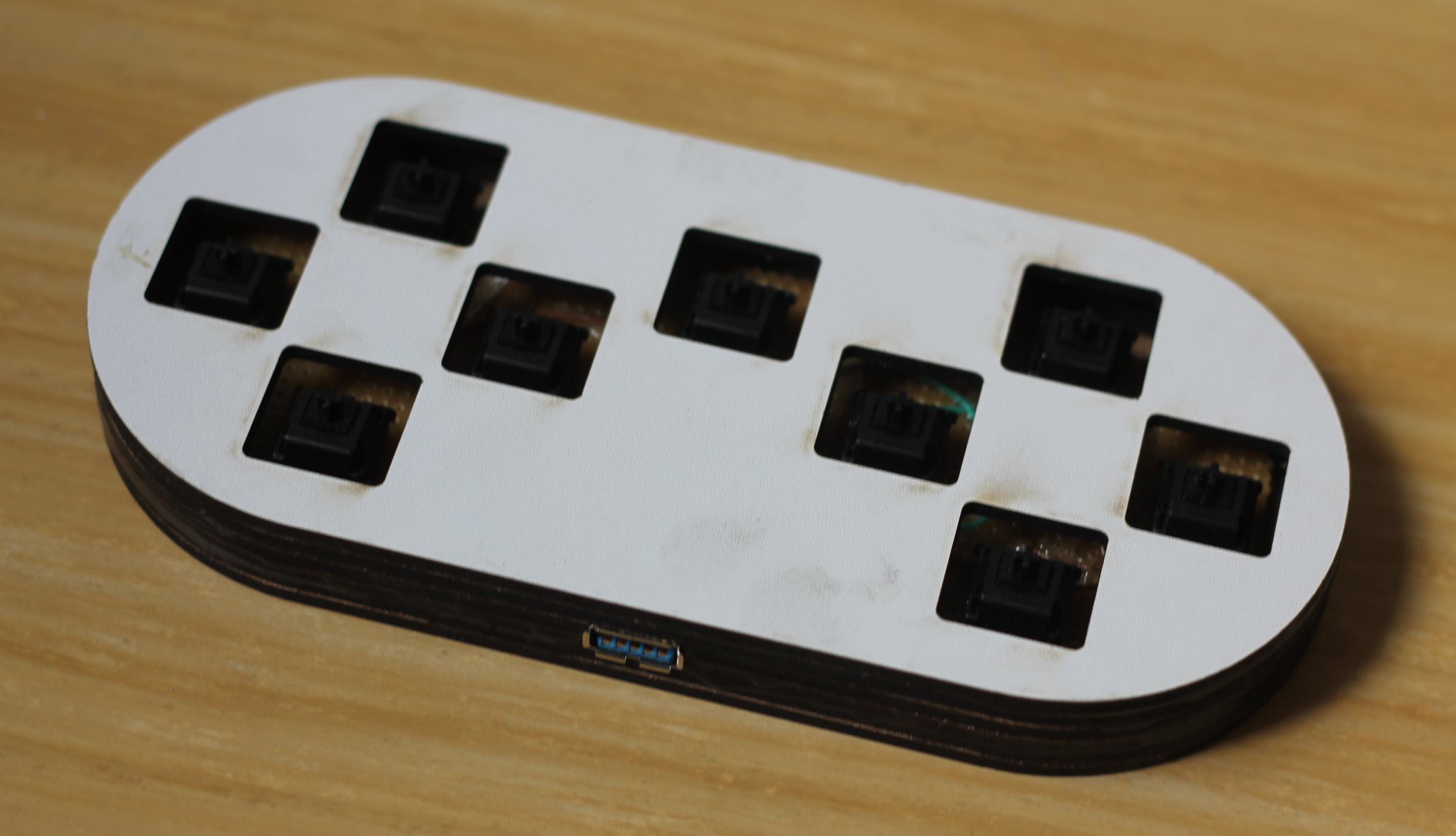
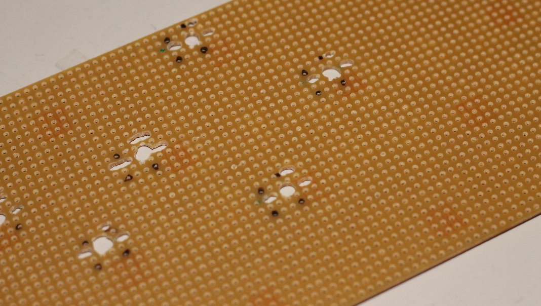
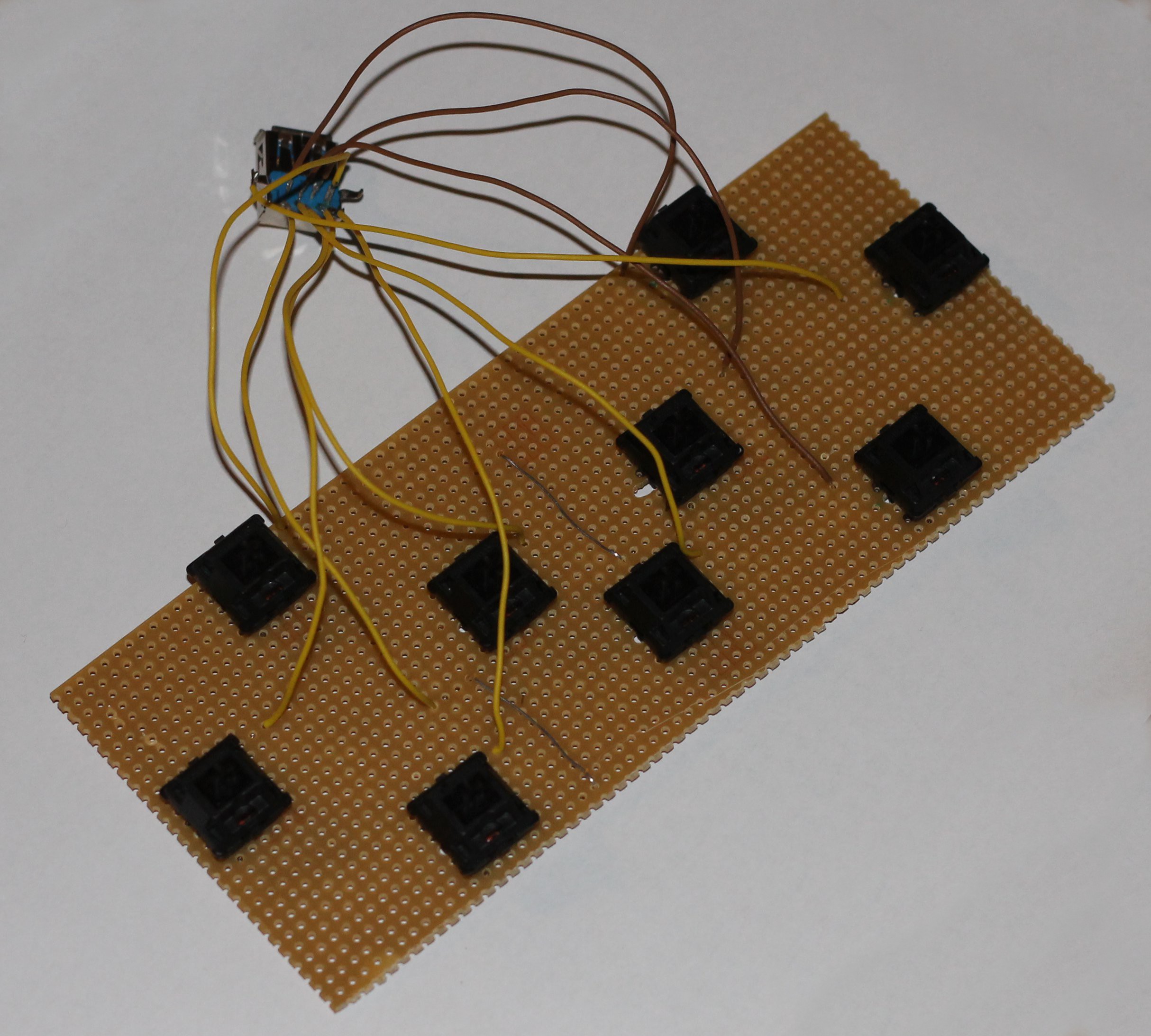
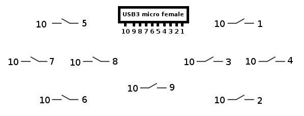
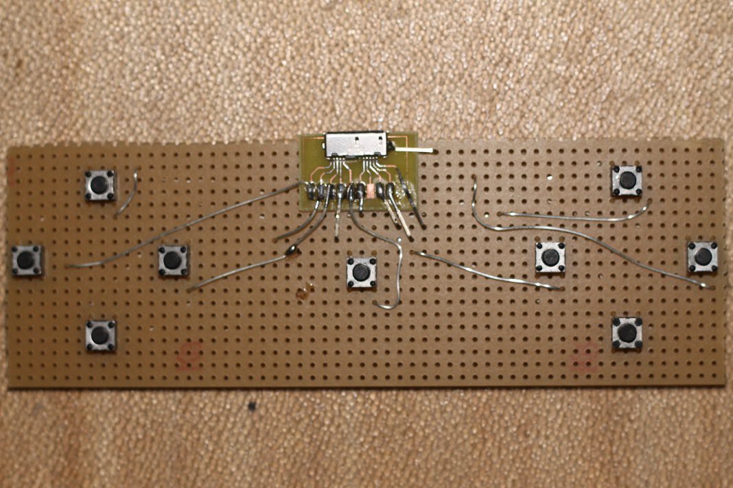
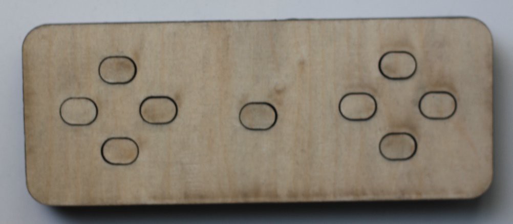
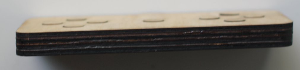
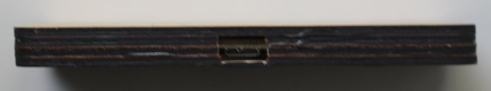
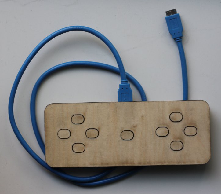
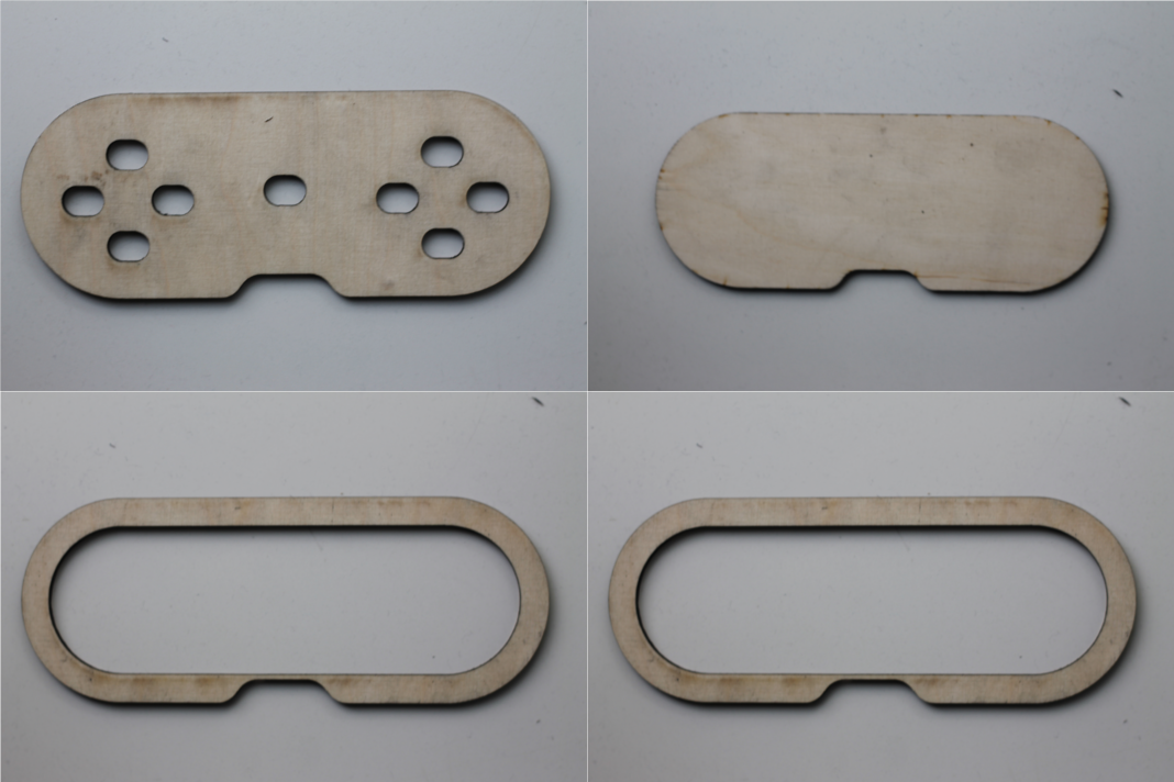
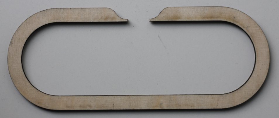
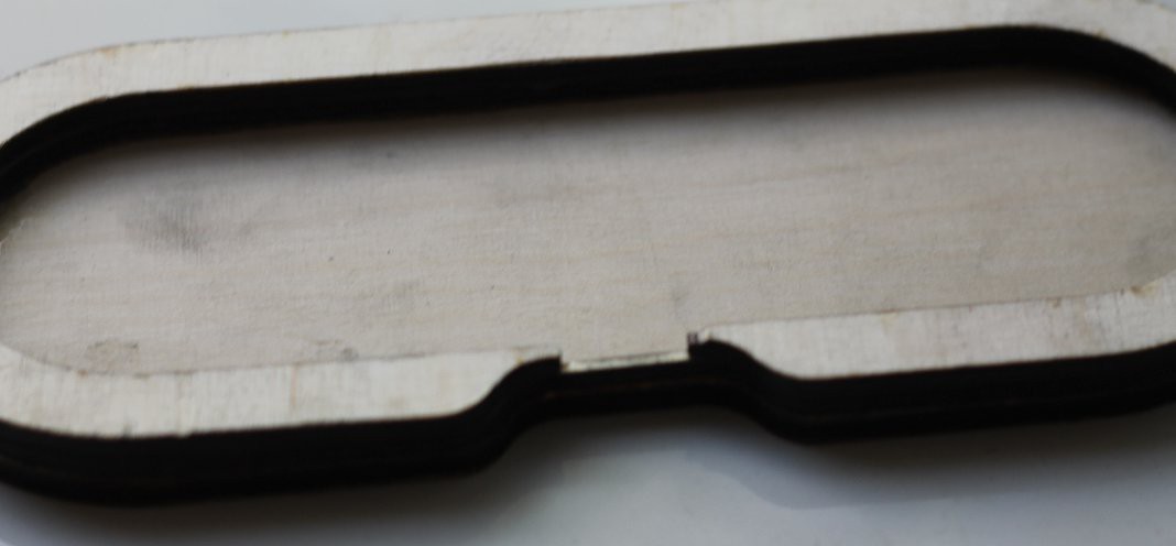
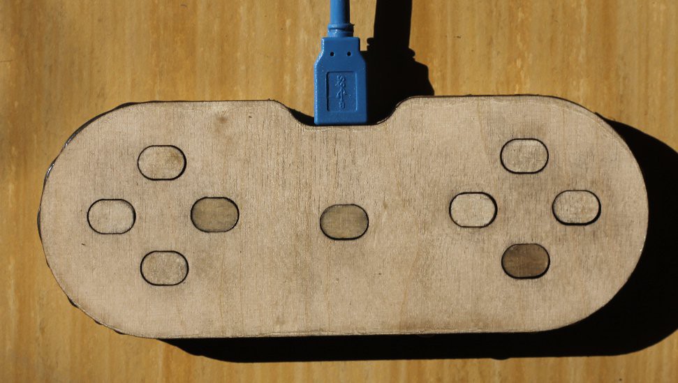
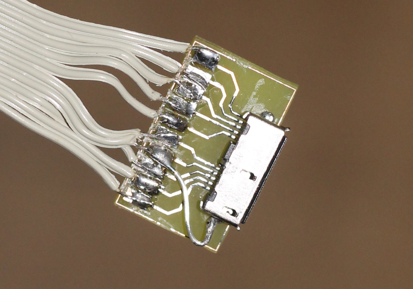
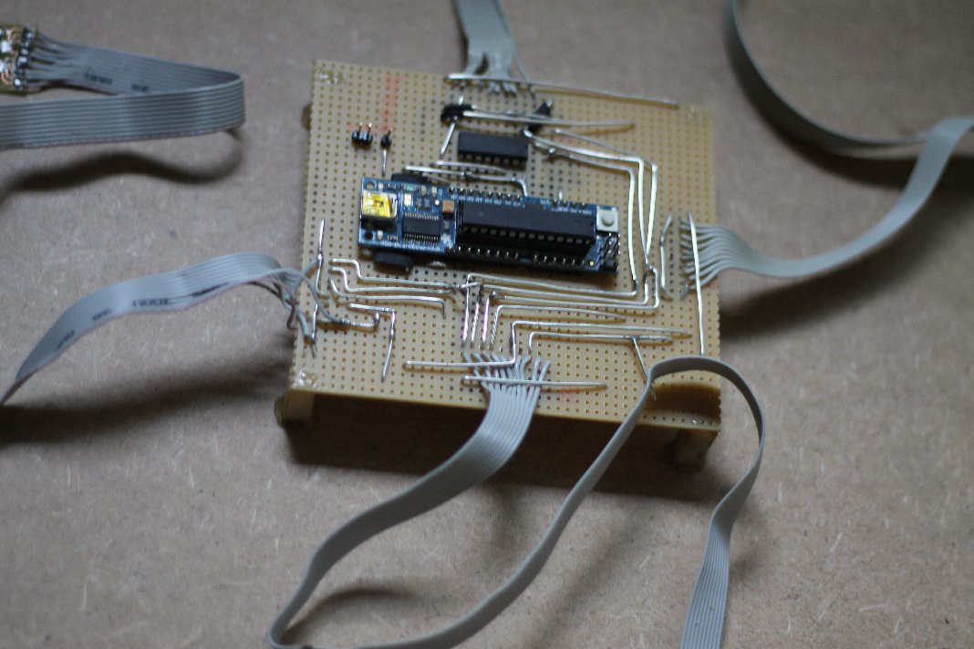
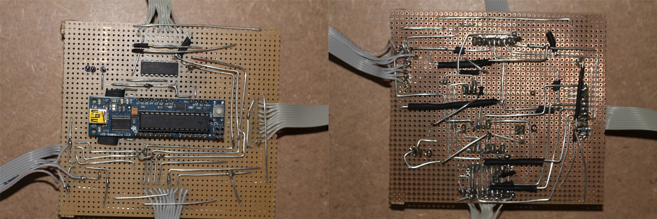
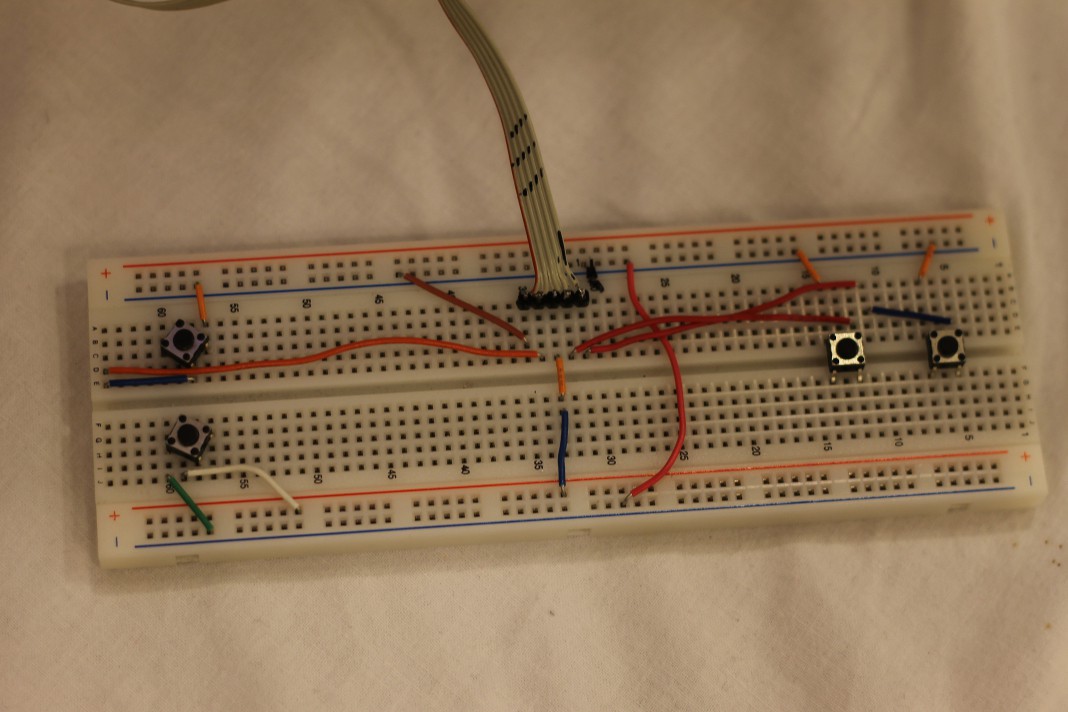
Controller
parts for controller case version 1: here.
and version 2: here.
Games
starthelp for your own game, Includes some usefull functions (everything is explained in the file).
If you wrote a cool game for the Social Gaming Cube you can send me a link to the code via comment or personal message and I'll put it here with a reference to you.


 John Anderson
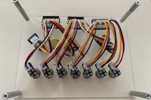
 Tom Dowad
 Arya
Arya
 Peter Walsh