 endevor100
I have never developed on the ARM platform before and I have an ATSAMD20E16A microprocessor layer around so I thought that it would be a perfect match for an eventual 8x8x8 cube. Because of this I wanted to develop this prototype cube to be as portable as possible to that eventuality. The ARM chips, as a whole, from Microchip/Atmel seem to all have I/O pins with a current capacity that is less than 10 mA so if I want to use this chip I need to use external circuitry to boost the current through the LEDs. The duty cycle is already pretty low so current needs to be maximized to ensure reasonable intensity. This thinking is what lead me down a long winding path of confusion and ultimately frustration that I do not recommend. In the end the solution is to use a microprocessor that can source and sink more than 20 mA per I/O pin. I will attempt to relive the futile efforts to design a discrete single input tri-state below, but I will be putting the ARM chip back on the shelf and using an Atmel ATMEGA328P going forward.
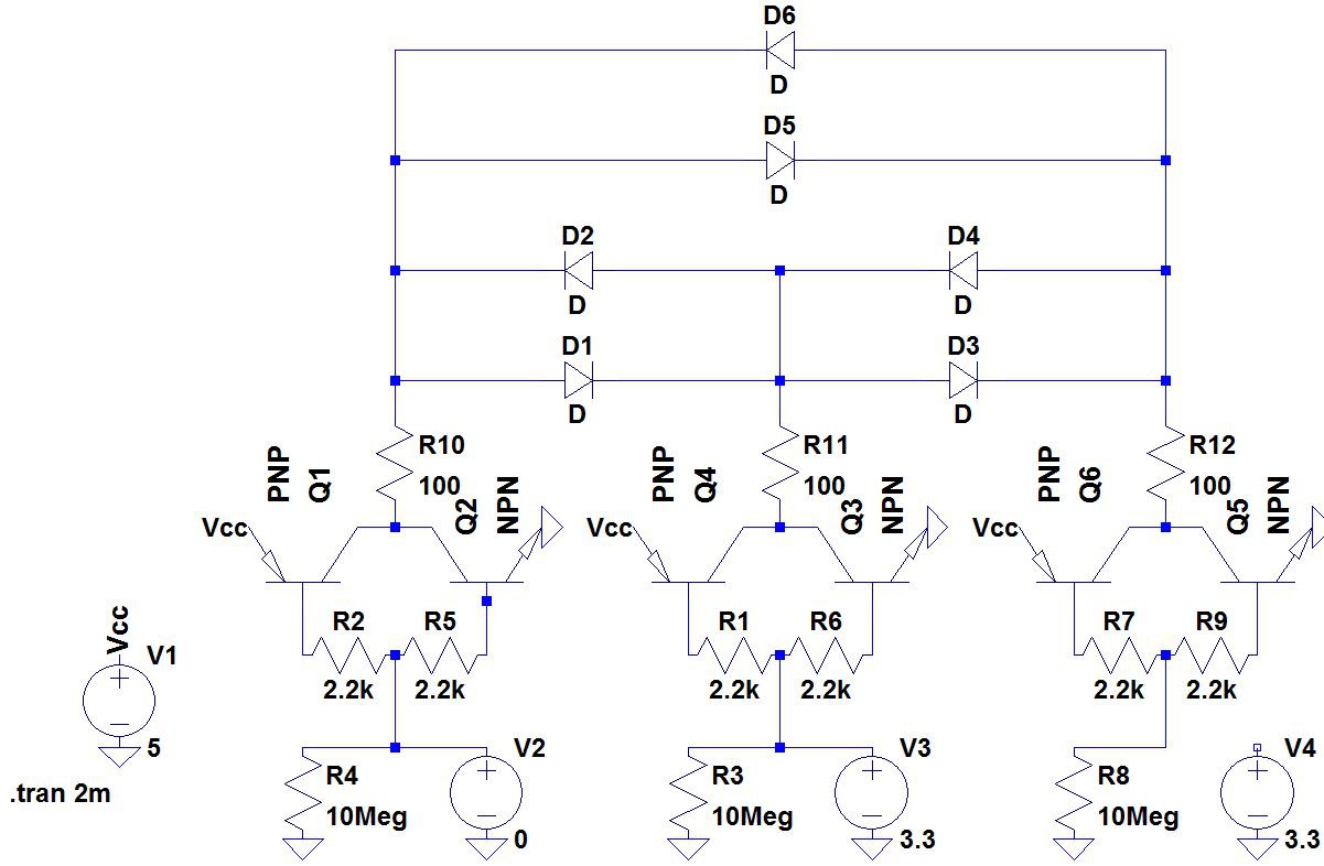
 Failed tri-state attempt #1
An LED is a current device so my first thought was to use BJTs to build my tri-state circuit. I built a circuit using an NPN transistor with its collector attached to Vcc, a PNP transistor with its collector attached to ground, and the base of both transistors attached to the I/O pin. I was also trying to be fancy and use an additional NPN transistor to regulate the current through each LED. In simulation this worked reasonably well, but once built on a breadboard it just never really worked out. As soon as I sent one pin high every LED with an anode connected to that pin would light up and I couldn't really get any kind of control over the cube.
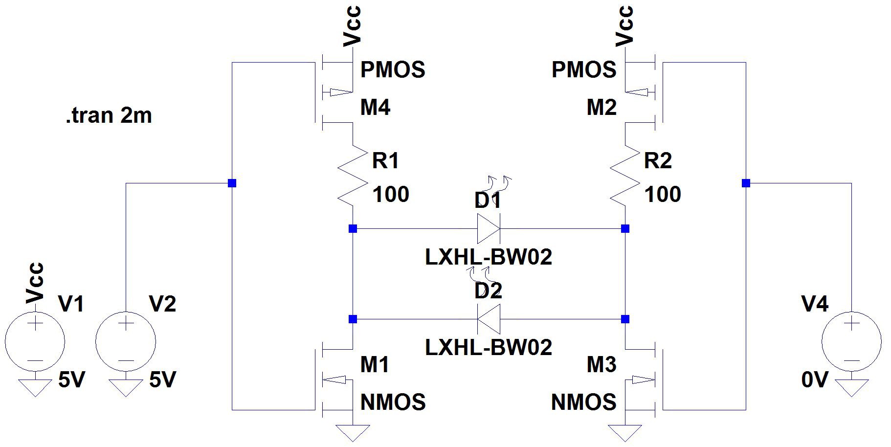 Failed attempt #2, this time with MOSFETs
I figured out that there was some cross contamination of current between transistor bases causing issues so I decided to try MOSFETs in place of BJTs. In simulation it seemed to work with a P-channel FET with it's source connected to Vcc and an N-channel FET with it's source connected to ground. The schematic as drawn more or less works, but the pin's high impedance state acts like a very weak pull down resistor. Because there is essentially no current flow from the pin to the gate the MOSFET gates are still pulled close to ground rather than becoming opens when the pin is in it's high impedance state. I fiddled with swapping the N-channel and P-channel MOSFETs with fairly similar results. I also tried mixing MOSFETs and BJTs and ultimately nothing involving MOSFETs worked very well.
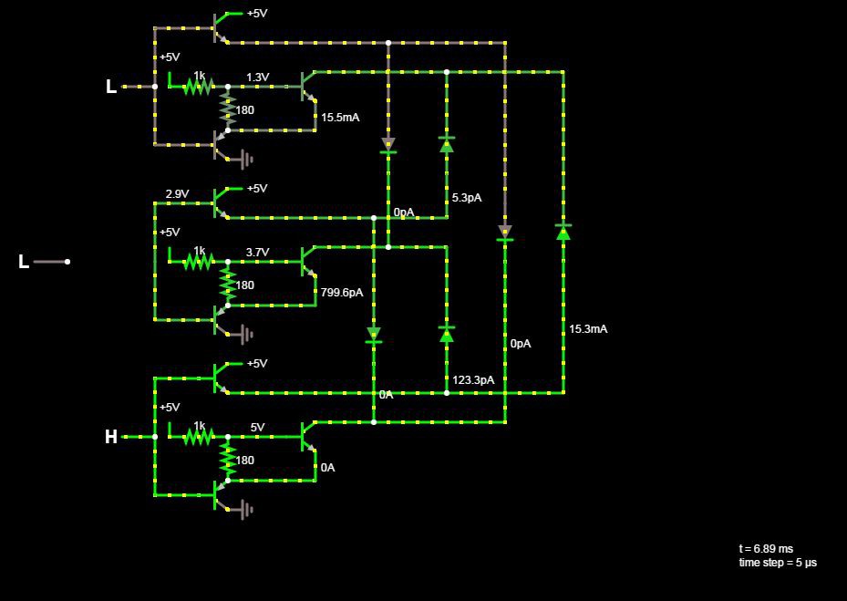
 Failed attempt #3, back to BJTs
Abandoning MOSFETs as not the right solution for a circuit that ultimately is trying to control current I moved back to BJTs. From this point I did my modeling with a 10 megaohm resistor to ground to represent the pin's high impedance state. In an effort to solve to problem of unintended current flowing between transistor bases I added two resistors connecting the bases together and injected the pin signal to the midpoint of the two resistors. My hope was that this would allow enough current to flow between the intended transistor and the pin while blocking the quiescent current that caused my first circuit to behave poorly. This worked really well in the LTSpice simulation so I was pretty hopeful going in only to be betrayed by what must be some of the most efficient LEDs I've ever come across. When one pin was high and another pin was in it's high impedance state I had something on the order of 50µA flowing through the LED controlled by those pins. Somehow this was still enough to cause a faint, but clearly visible glow from the LED. I varied all of the current limiting resistor values through a pretty wide array of values and the intensity of the undesired glow never really changed while the intensity of the LED when it was supposed to be on got worse and worse.
I modeled a few other solutions, but didn't even build them on the breadboard. Every discrete tri-state circuit I found requires two inputs which really cuts down on the advantages of Charlieplexing. At this point I gave up and am just going to go on with a non-ARM microcontroller with pins that can drive the LEDs without additional circuitry.
Discussions
Become a Hackaday.io Member
Create an account to leave a comment. Already have an account? Log In.