 Yann Guidon / YGDES
Digital data display is a recurring and nagging problem when designing DIY computers !
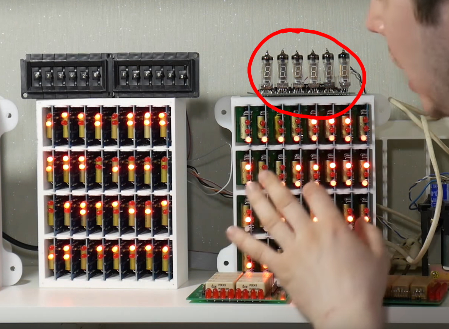
Look at @Artem Kashkanov 's #BrainfuckPC Relay Computer : it uses VFD tubes but they are driven by semiconductors.
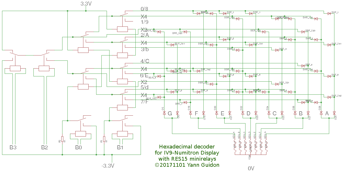
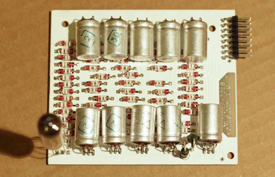
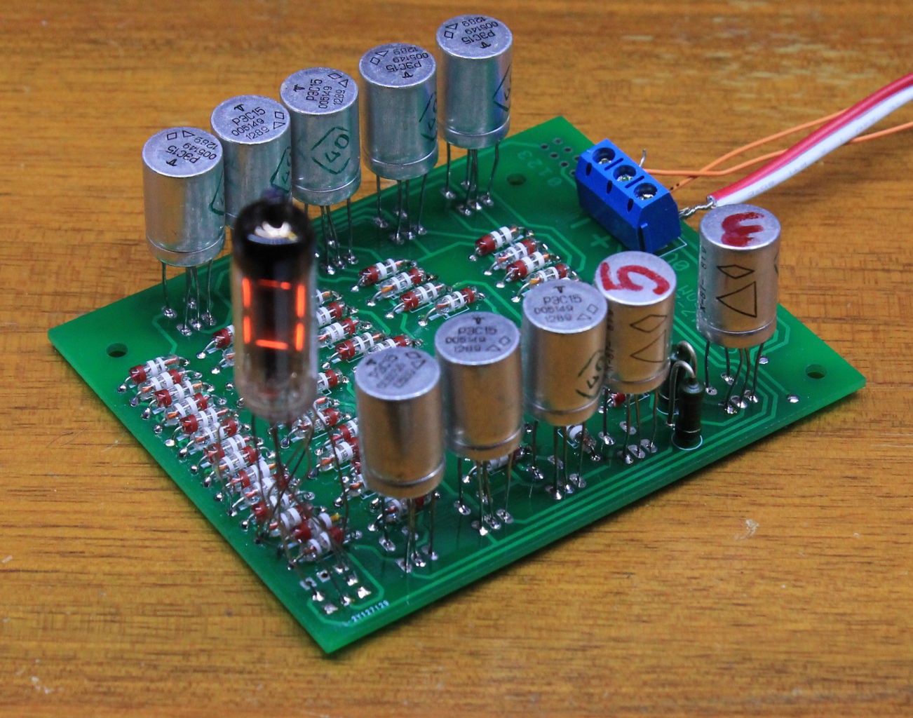
In the case of #YGREC-РЭС15-bis the constraint is to avoid using transistors. This all-Russian neovintage module uses
- РЭС15 minirelays
- IV-9 Numitron tubes
- D9K Soviet germanium diodes
This project is also a continuation of the log 20. Display technology again (yes, another fork !) and I'll move the relevant discussions here.
The logs explain the 3 methods I've invented to keep the parts count low. Some optimisations are pretty neat !
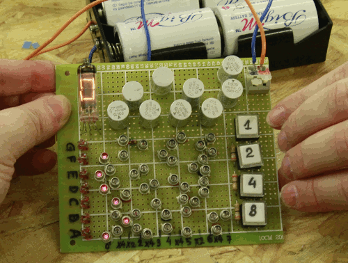
Ideally, like the #DYPLED, I should be able to design and build individual modules for my own use and for eventual #Hackaday TTLers fellows :-) This would be a step even further than the NUMI-311 (TIL311 module replacement) because of the increased power draw and the increased room. However it will be warmer (both sentimentally and thermally) and you could show a kid the inside "for educational purposes". Who would not want to play with the buttons ?
One design constraint is to keep the input impedance identical and low for all the data bits, to ease integration with other YGREC devices.
Power supplies are derived from experience with the #YGREC-РЭС15-bis so we're using -3.3V, 0V and 3.3V power rails. Using a single power supply would be too much of a hassle and increase the complexity and the Numitron draws little compared to the relays...
Pinout :
| 1 | b3a | b3b |
| 2 | b2a | b2b |
| 3 | b1a | b1b |
| 4 | b0a | b0b |
| 5 | V- | V- |
| 6 | V+ | V+ |
| 7 | 0V | 0V |
| 8 | Zero flag | key |
Logs:
1. Prior art
2. References
3. Physical configuration
4. Circuit and schematics
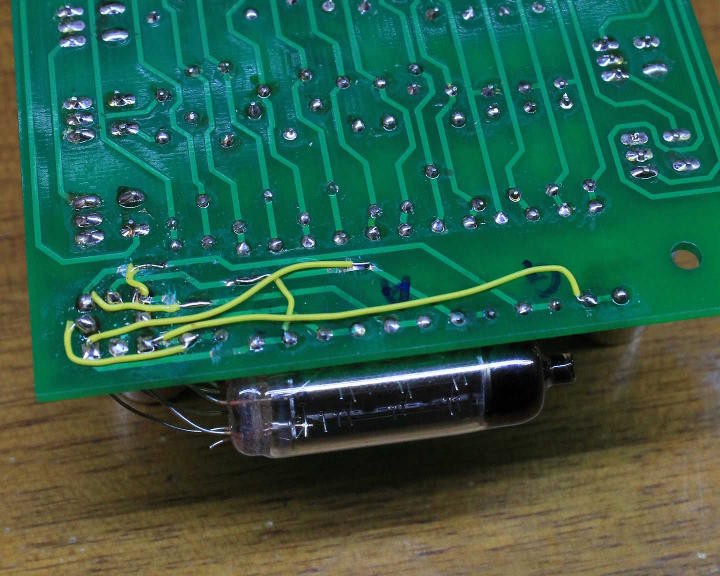
5. First prototype and first setback
6. More diodes !
7. Diode optimisation
8. Going further
9. A less preliminary layout
10. A little idea to revive...
11. Another mistake
12. Second valid prototype
13. A new ROM layout generation script
14. Beyond the prototypes
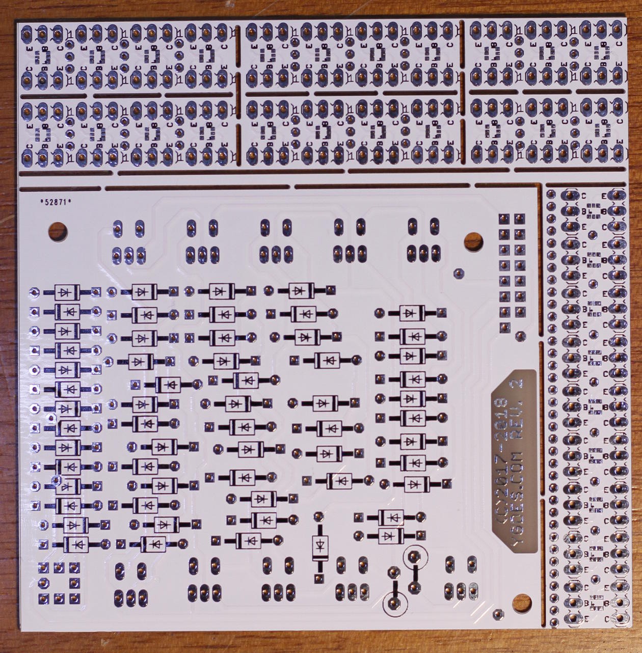
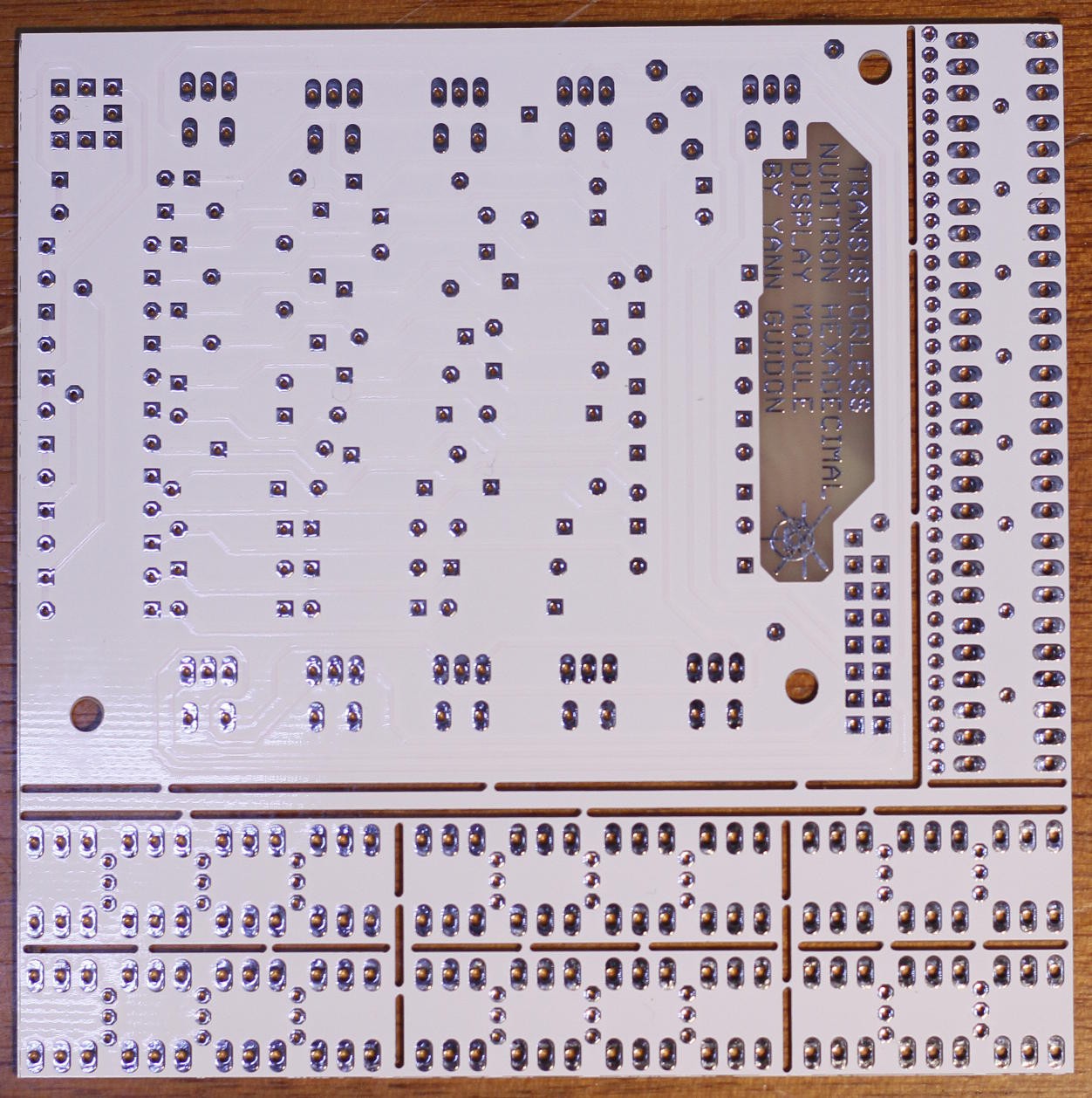
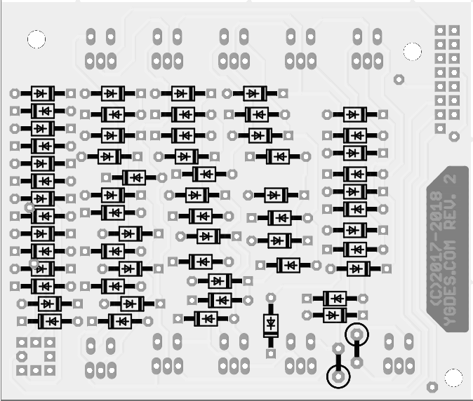
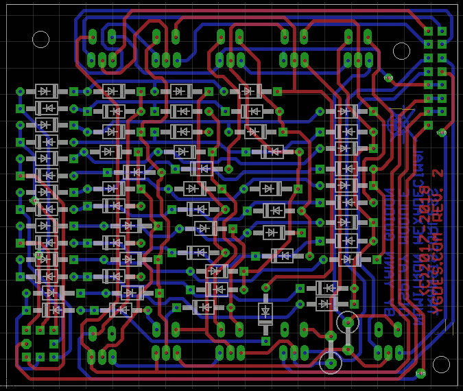
15. PCB
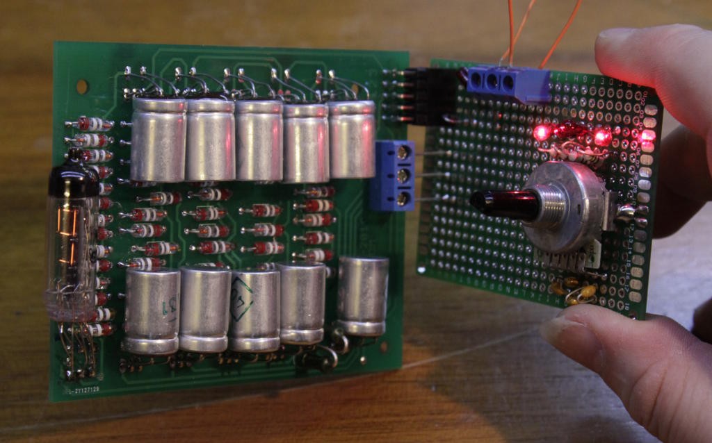
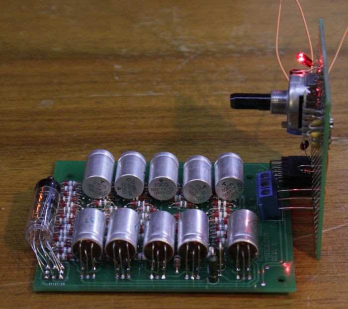
16. The demonstrator goes portable !
17. Enhancements
18. New layout
19. PCB prototype
20. Cascading the LZB
21. PCB delivered !
22. What would the Russians do ?
23. Patched
24. And it works !
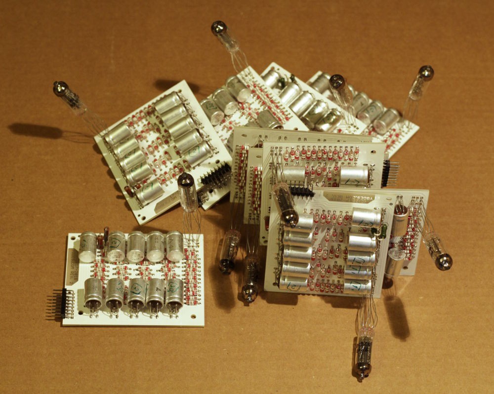
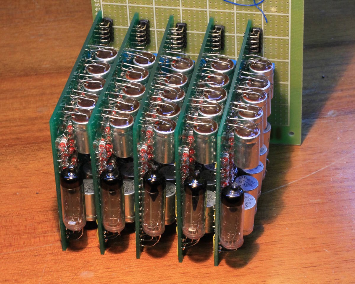
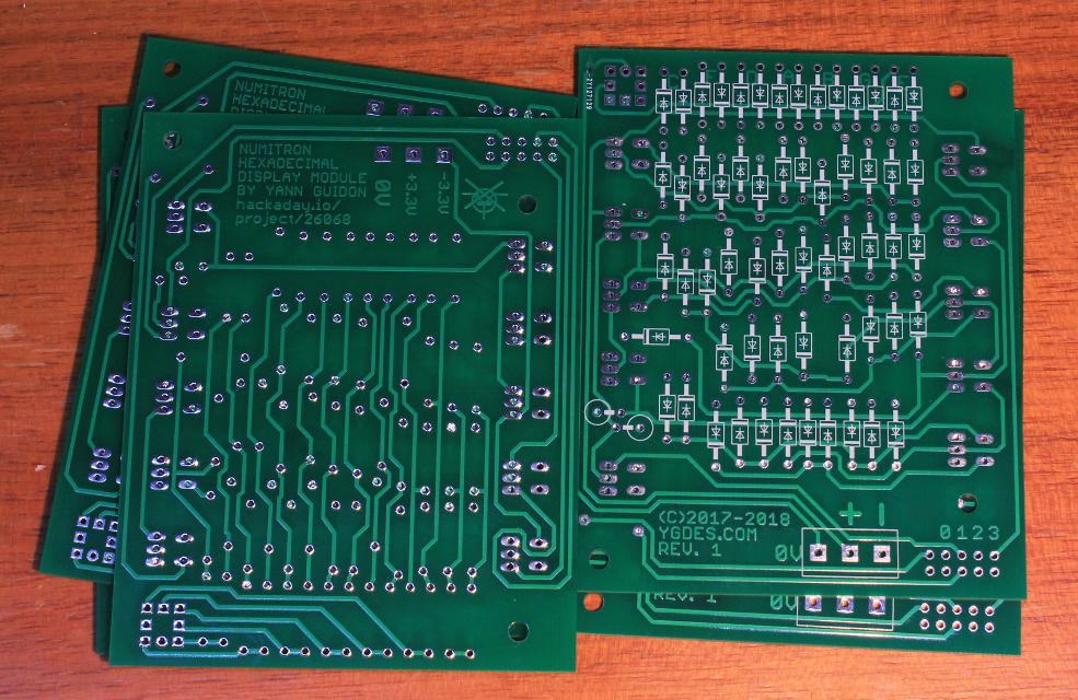
25. More boards
26. 5 modules
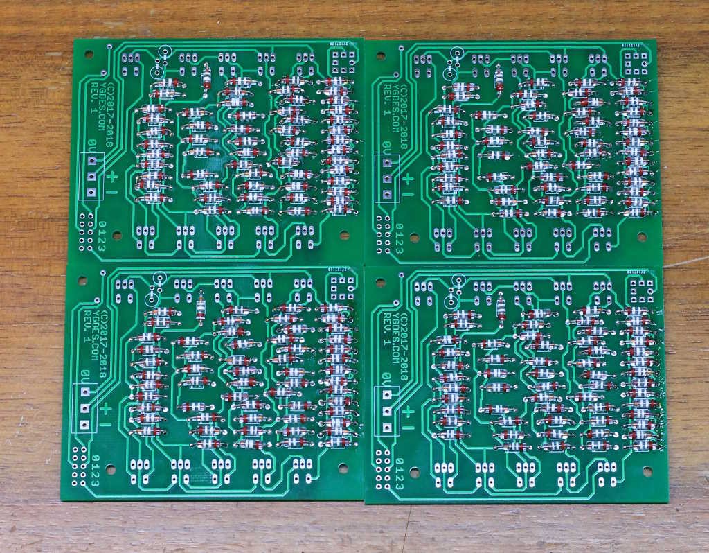
27. New layout
28. New PCB batch
29. PCB delivered !
30. 10 units
.


Brian does seem to do a lot of promotion for this side-project, which is pretty unexpected but always welcome :-)
http://hackaday.com/2018/04/25/video-quick-bit-numitrons-and-infinite-build-volumes/
Time to finish the 4 other boards !