Emma Barme
-
Rough prototype of foot bracelet with sensors
07/31/2017 at 08:50 • 0 commentsTaking into account the size of the various electronic components we have to include in the wearable, and the constraints associated with the sensors, we have decided to focus on a foot wearable. The sensors will be placed on the top and bottom of the foot thanks to a textile sock/bracelet part. The rest of the components (battery, wifi and micro chip) will be held in an ankle or thigh bracelet.
Because we have not yet settled on the exact battery, wifi module and micro chip we want to use, we focussed first on the sensors part of our wearable.
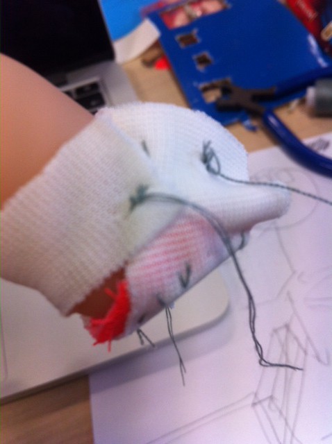
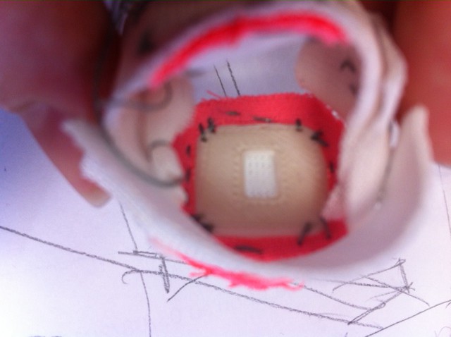
Below are photos of our first, very rough prototype. For each sensor, we are using a made-to-fit 3D-printed plastic case. Right now it is hard plastic but ideally, it would be made of medical-grade silicon.
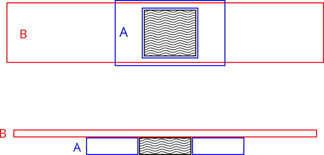
A window of the size of the case is cut into a thick slightly elastic fabric A. The case is placed in this window. Both the thick textile A and the case are sewn onto a thinner and more elastic textile B. [See diagram below, top is the view from the inside and bottom is a longitudinal cut]
![]()
We placed the temperature sensor above the foot because it was slightly smaller and did not require contact, and the heart-rate and SPO2 sensor below it on the flatter sole part. We added a short elastic strap around the ankle to maintain the whole thing in place.
![]()
![]()
-
Layer design of the companion device
07/28/2017 at 09:11 • 0 commentsAs explained in a previous log, design the companion device as a cube made of a single piece turned out to be impractical. Our new approach is to design it in layers.
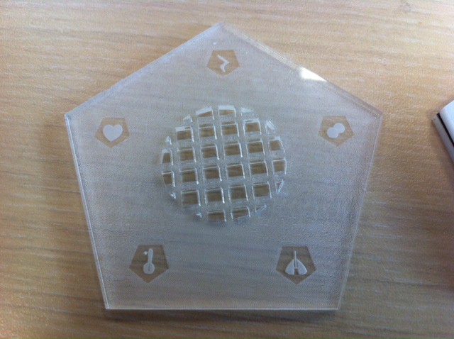
The first layer is in plexiglass. The partially opaque white material is used to diffuse the light from LEDs placed behind. The face is cut as a pentagon with a laser cutter. In the centre, we have hollowed out a round grid-like window so the speaker can be placed underneath. We have also engraved five icons where the LEDs will be to label each information.
![]()
[First try with transparent plexiglass]
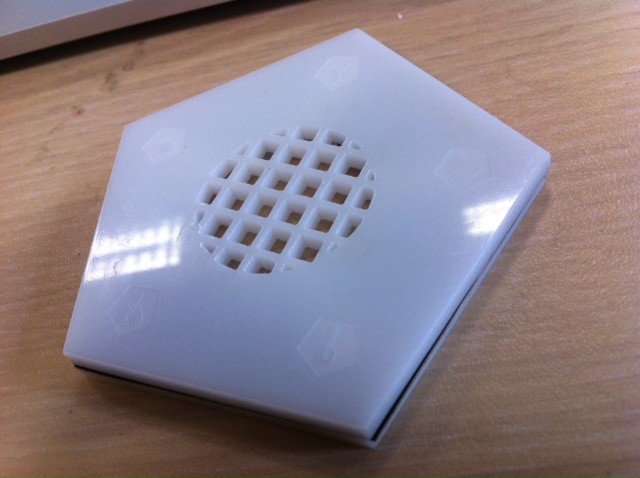
Under this plexiglass cover, we are designing layers to hold the components and wiring. For now, we have defined the layers to hold the LEDs and the speaker. Below will probably be the microchip and the Wifi module. Once we have defined if and how we also give visual information on the advice for parents, we will add them to the design.
![]()
[Second try, from top to bottom: cover layer in white plexiglass, black paper layer to focus the light, plexiglass layer to hold the LEDs and speakers]
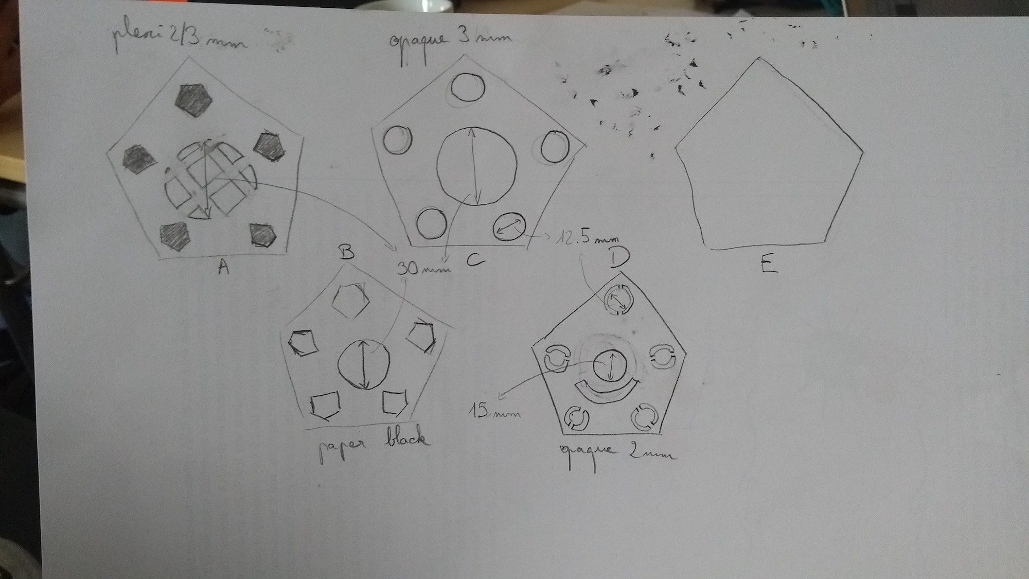
This layered design is mostly for us to iterate. Afterwards, we will probably merge most layers together. We will also have to design a way to keep the layers together.
![]()
[Draft of the 4 first layers]
-
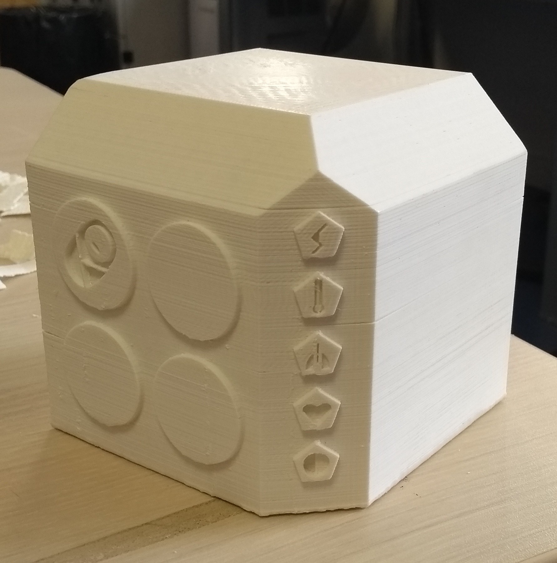
Design of the companion device
07/26/2017 at 15:47 • 0 commentsFirst prototype for the companion device has finished printing. To access the src file look at the github page under models.
Some specifications of the object: it will receive data from the monitoring device and alert the parent when they need to take action in order to help their child. We currently want to add a speaker and some LEDs to alert and provide guidance. Let us know if you have any ideas. :-)
All in all, we made a lot of mistakes printing this prototype. Special Guest Jean-Ernestin Von Klinex agreed to give his opinion on it here:
" Did you use the printer for 35 hours to print a god damn cube? *Begin to laugh extensivly* "In more details, it was a bad idea:
- to start prototyping in 3D printing when we could have done it faster with cardboard
- to print the entire cube when we could have printed only the three faces we needed
- to print with 80% (more or less) infill instead of 10%. This was actually not our mistake, something apparently went wrong with the communication from the software to the machine. However, we should have stopped the printing process when we realised it was not printing with the right settings
- to print with support for the face decorations when just turning the object would have removed the need for supports
![]()
-
Sending Data to the Companion Device
07/26/2017 at 13:54 • 0 commentsTo send data to the companion device several methods have been discussed. As we aim to provide this device to developing countries it is not guaranteed that access to internet will be accessible in all locations. Thus several methods have been tested to make the device usable by all who need it.
Possible solutions
Bluetooth Low Energy: BLE is one of the most common solutions which comes to mind when the internet is not available for transmitting data. As this system does not use a lot of energy and therefore saves battery we might use it in the final product depending on the flow rate required to send the data from the monitoring device to the companion device. However prototyping with BLE is hard to do hence we looked for another solution.
ESP: This method of communication is relatively simple to use and has a high flow rate. Very cheap. nearly 5 times as much data ram needed (regarding the issue talked about in the previous log). It can either be an access point or an emitter (which would cover both the monitoring device and the companion device). In terms of size it is small enough to be fixed on the monitoring device.
Figures of the different emitters&receivers :
 ESP on the left BLE on the right.
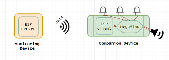
 These processes still need to be tested as the project evolves. For now we are concentrating on using two ESPs. Here is a schema of how the process will work:
More information will be posted once further results are obtained.
-
Choosing a Heart Rate and Pulse Oximetry Sensor
07/26/2017 at 11:47 • 0 commentsOne of the device constraints for this project is the size of the monitoring device. Typically premature babies have very small hands and ankles. Hence, choosing the different sensors we privileged size and accuracy.
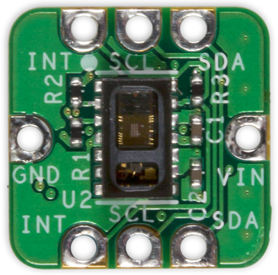
We chose the MAX30102 "High-Sensitivity Pulse Oximeter and Heart-Rate Sensor for Wearable Health" to measure the Pulse Oximeter and Heart-Rate of the child.
![]()
Source code mostly taken from https://www.digikey.com/en/articles/techzone/2016/oct/maxrefdes117-heart-rate-and-pulse-oximetry-monitor but modified to allow the calculation of the BPM and SPO2 at the same time. Main problems we currently have are the small size of the ram of the Arduino and trouble determining a correct BPM.
More info on the problems encountered:
Small Sized Ram: The Arduino Genuino Uno has a Ram of 2kB and the calculations of the BPM/SP02 require 86-96% of the memory. To reduce the ram used we reduced the data stored before averaging to calculate the different measurements. We also refactored the code. As the monitoring device is paired with a companion object which provides advice to the parents a possible solution would be to send the data directly to the companion and do all the calculations there. The advantages of this method revolve around the scale-able size of the companion object which allows more memory and processing power. Possible disadvantages include poor connections between the objects.
Trouble determining the correct BPM: The BPM calculations used to work correctly at the start when measuring it alone. Perhaps the sensor was damaged, however as we have followed the simple instructions that come with it we are not sure. A second sensor is arriving in a few days time so this question should be resolved. We also tried different codes and measuring the BPM on its own (after combining it to test it) to no avail.
PreemieAlert
A frugal connected wearable to support caretakers in tending to premature babies #SDGclass2017
 ESP on the left BLE on the right.