 agp.cooper
Test 1 - No PROM
Only a problem if the CPU does anything.
Nothing happening on the daughter boards but the reset works.
I took off the Register board to get at the Control board.
Yes the clock is going but not much else.
It should be locked into 0xFF or JMP Spare 2. Spare 2 will read 0xFF.
So it is locked into an infinite loop at 0xFF.
All I can confirm is:
- Clock is present at the PC counter.
- The PC is Loading (!LOAD is low) 0xFF (actually LS-TTL floating inputs)
- The decoder is 0xFF.
So far so good.
Test 2 - Unprogrammed PROM.
This should read 0x00 or ALU_A ADD.
So unless ALU_B is not zero, I should see lots of noise.
The C Bus counting in unknown steps and the PC counting 0x00 through to 0xFF and rolling over.
Well the instruction decodes but both the A and B registers always fire up as zero so not much to see. Reset and power up does not randomise. This is a little unusual but not identifiable as a fault at the moment. The pins read as expected (for zero).
Took off the daughter boards and the PC is clocking away as it should
So far all good.
Test 3 - Burn a Test Code
Okay I went for broke and uploaded the Demonstration Monitor.
One last manual check, transferred the hex code the the Arduino and fired up the PROM burner. Error! And again, error.
What to do? Okay I have a 4 bit Front Panel that I can use to read the PROM.
Yes it has been programmed.
Transfer the code back to the spreadsheet I have been using to write the code.
Check it has written correctly. All good!
Okay, I used a old piece of code and I have changed the data sense arrangement on the PROM burner, it probably does not .
Okay, download the lasted version and no better. But at least both PROMs are coded correctly. I am sure the sense was working the last time I used it!
I will look at the problem later.
---
Fitted the PROMs and fired up the CPU. Signals but not working. Worse it seems random.
Bad noise on the !WR_ALU_A signal, traced it back to the clock. The clock is bananas!
It did settle down but now it is in an infinte loop around 0x00 and 0xFF executing ADD and obviously a JMP. The CARRY signal is active.
I can pull the crystal and feed in an external clock signal ... tomorrow.
---
The executed code must be:
ADDR  INST
0xFF  0X00 (ALU_A,ADD)
0X00  0XDD (LDI, IMM)
0X01  0XFF (DATA)
But the CPI thinks the 0XFF is JMP (JMP 0XFF). The LDI instruction is not working. Well I now know where to look.
---
This is stressful so pack it up and do something else until tomorrow.
Tomorrow is Today
Removed the crystal and associated components. Damaged one of the pads (not unexpected with these cheap boards), hooked up a 10kHz schmitt trigger oscillator.
Got a pencil, an eraser, some graph paper and my oscilloscope, and start tracing signal through the control board. After three hours I have worked out:
- The PROM is loaded and reading correctly.
- The instruction cycle is:
- 0xFF 0x00 (ALU_A ADD)
- 0x00 0xDD (LDI IMM)
- 0x01 0xFF (DATA)
- The data does appear to be clocked into the IMM register.
- The DATA (0xFF) is ALSO being interpreted as a JMP 0xFF.
- There are glitches (they may be absorbed) out of WRITE decoders.
- I have inverted the PC CLOCK to suit load immediate (LDI) but now the PC LOAD may be too early (i.e. the PC CLOCK too late).
Redesign Completed
Too many issues to fix with a jumper or two. Redesigned the CPU control board, addressing all the issues identified. Some additional enhancements as well. The OpCodes have changed so the old PROM is now useless.
Fixed:
- the jump problem
- the write glitch
- the PC load issue
- the clock (it is now a schmitt trigger)
- added JNC and RD_PORT to the OpCodes
- made register A read/write
- made register B read/write
Cost was one additional chip (a 3x 3 input NOR gate).
The OpCodes (Version B) are now:

So I can now store data temporarily in the ALU without penalty.
The other reason for the rearrangement is so that it is more PROM reuse friendly.
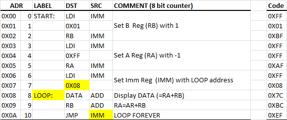
Here is some code for an 8 bit counter:
Back to CPU4A
I finished the PCB design for CPU4B but so not to waste the two existing daughter boards, I have reworked the old control board (CPU4A!) and sent it off for fabrication.
AlanX
Discussions
Become a Hackaday.io Member
Create an account to leave a comment. Already have an account? Log In.