Close
0%
0%

Honda OBD1 Digital Tachometer

In this project I'm building a digital tachometer for 90's Hondas.

Similar projects worth following
Using the tools available to me I'll be designing a digital tachometer for 90's Hondas. Some design goals include easy to install, aesthetically pleasing and most importantly accuracy. The factory tachometers tend to have issues above 5500RPM so I'm hoping to be able to remain accurate above those levels.

This project is one of those ones that start out of neccessity. My manual 90's civic felt that it was too cool to have a tachometer. To remedy this, I began to work on the project this summer. Right now the hardware is pretty much all off the shelf kit and the end goal is to move over to a custom single PCB implementation. Additionally, while testing the filters I just used Arduino code to get things done fast. Now that the hardware is verified and the code flow work to my satisfaction I will be porting over the code to C along with the hardware revision. I'm hoping that reading the input pulse from the car counts as connected. :p

The goal is to release the code and hardware files all as open source. I hope others try my design out so I can see just how many different Hondas this design actually works for.

Current Features:

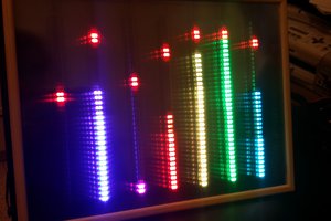
4 Digit 7 Segment based RPM Output.

2 RGB LEDs for a shift light and redline.

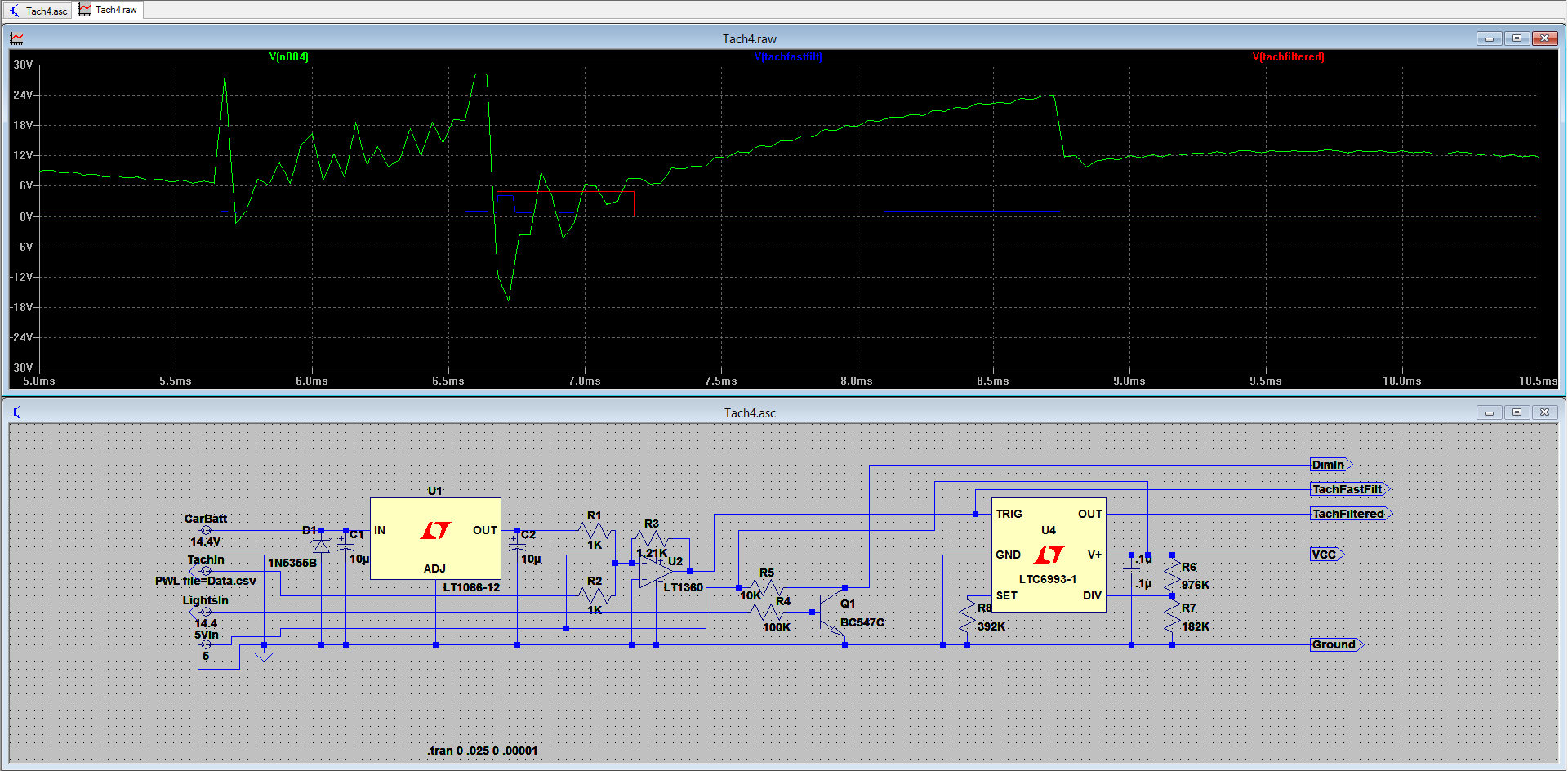
Rolling averaging and jitter reduction for readability while keeping a fast response time.

Connects to car via a 4 pin connector spliced into the cluster loom.

Automatic dimming when instrument cluster lights are turned on.

Car off detection.

  • 1 × 1/8in black ABS sheet
  • 1 × Arduino Pro Mini 5V
  • 1 × Sparkfun Serial 7 Segment Display
  • 1 × DE-SW050 5V Switching Regulator
  • 1 × LTV-816 Opto-isolator

  • Delaaaaaaysssss

    Nigel02/09/2015 at 04:09 1 comment

    Sorry for the lack of updates. I ended up getting an internship at Tesla so work has been keeping me really busy and my car and equipment are currently 2k KM's away which also makes things difficult. I've made a few more changes to the circuit and it's now more closely based on a standard comparator instead of an inverting amp. Will have those LTSpice images up soonish and also should hopefully be adding some updated C code to the git shortly.

  • Completed System Design

    Nigel11/07/2014 at 22:00 0 comments

    I think I've now completed the system design. The vibrator IC might not be completely required but will help with stability/sensitivity. This new SPICE sim also includes the cluster light input.

  • New Filter Design

    Nigel11/03/2014 at 05:44 0 comments

    I've found a new, and hopefully more reliable and robust method of filtering the input signal from the tach. It uses an op amp in an inverting summing amplifier configuration. Next step is to order parts and breadboard it. Thanks for reading!

  • Call for help!

    Nigel11/03/2014 at 03:36 0 comments

    I'm working on a 2nd method of filtering the tach input signal. My next idea is trying to use the negative pulse to trigger a mono-stable vibrator to give some control over the pulse width. I'm working on isolating the negative pulse that falls below -10V or so but I'm struggling to come up with something that works. Anyone have any suggestions for possible methods of doing this?

    EDIT: Is using a summing amplifier (other voltage source being VBATT) to shift the wave up followed by blocking all the positive components to isolate that negative components we want ok? It should work, but are there any alternatives that would be better?

    EDIT2: Using an op amp in an inverting summing amp? It would eliminate the need for the extra blocking step and conveniently inverting the good signal for us. Putting it into sim now.

  • Video!

    Nigel08/21/2014 at 04:18 0 comments

    The video is done! Check it out here: 

  • Code Overview

    Nigel08/21/2014 at 04:13 0 comments

    I'll go over the code in chunks. Instead of pasting it here, please open up the bitbucket repo or the .ino file in an IDE and follow along with the line numbers.

    Lines 1-30: Basic declarations and includes nothing special here.

    Lines 32-89: This is our initialization step. We start up software serial (using this because of how often I'm updating the firmware. I want to keep the HW serial free for now. It then runs through the little start up routine so you can check for any issues with the display. After than it latches the interrupt to wait for the first pulse of the car to begin measurements.

    Lines 91-98: Main loop. Super simple, just keep looping and if more than .1 seconds have passed since the last screen update, update the screen.

    Lines 100-106: Fresh start routine. Pretty much resets the timing so that the very first measurement is accurate and doesn't take in a ridiculously long value.

    Lines 108-121: Stores the time between pulses in an array. It rolls through the 5 locations in the array to gives us our values that we then average.

    Lines 121-173: This is the anti-jitter code. I found this on the Arduino forums years ago and haven't been able to find the original thread to give credit to. It takes in the to be displayed value and a threshold and determines if the value is ok to display. It looks for either two consecutive values trending in the same direction or the gap between two values is larger than the specified threshold.

    Lines 174-187: The code that does the actual writing. Since the display expects 4 digits per send we must send a null character if the number is less than 1000.

    Lines 189-233: This is the function that actually calculates the RPM to update. First it checks to see if it is in the correct state for display dim. Then it calculates the RPM from the stored pulse times. Following this is it checks to see if it needs to turn on any of the LED's , as well as if it needs to display the car is off. Finally it sends the RPM value to be printed on screen and the process starts over again.

  • The Filter

    Nigel08/19/2014 at 20:07 0 comments

    The filter is probably the trickiest part of this project for me. This was my first time using LTSpice and overall I'm happy with the results. I was able to create a working filter in the program and then breadboard (and then perfboard) a working filter from the design.

    The input waveform:

    I've unfortunately deleted the original waveform files I had saved from my Rigol 1052E but I'll remake them as soon as I can. (EDIT: Added pics) The basics of the waveform was that it was a +-20Vish super noisy pulsing waveform. The main challenge I faced was making this into something the Arduino can read while still preserving the data integrity. Simulation tools were used in order to achieve this.

    The Filter:

    This is the current revision of the filter. It takes the waveform in from the car and converts it into a 5V square wave. The intention of the first RC stage is to reduce some of the noise coming from the input. After this, the two Zeners are for first truncating the waveform to remove any false positives and then cut off the voltage at 5.1V to protect the opto-isolator from any spikes in voltage.

  • To Do:

    Nigel08/19/2014 at 19:47 0 comments

    First log update, figured the To-Do section would be a good place to start.

    Contest Specific:

    1) Get pictures up. Done

    2) Finish Logs. Done

    3) Get video up.Done

    4) Clean up project page. Done

    Overall:

    1) Sort out Git for the software. DONE

    2) Refine current hardware design.

    3) Design new single PCB layout with new hardware. Get it made.

    4) Port over and clean up code to C.

    5) Design new case and get it printed.

    6) Assemble, and chill.

View all 8 project logs

Enjoy this project?

Share

Discussions

michele wrote 12/23/2019 at 11:05 point

Any news on this project? I am trying to do the same. Get the tachometer signal from distributor to measure the RPM and with that drive a LED BAR with gear shift..

  Are you sure? yes | no

geraldjust wrote 08/21/2016 at 01:25 point

If your looking for a way to read the RPM this is the simplest circuit. https://wiki.autosportlabs.com/CoilX this is the best way. it works on any car with old school (-)coil tach signal.

  Are you sure? yes | no

Nigel wrote 08/21/2016 at 01:36 point

Wouldn't work with the signal at the dash. CoilX cuts off below 75V and in this case the negative spike is less likely to have false triggers.

  Are you sure? yes | no

Nigel wrote 10/08/2014 at 01:55 point
Sorry for the delay guys. Have had some other time sensitive things come up so this project has had to take a bit of a sideline. I hope to get back working on things very soon.

  Are you sure? yes | no

CJ Rose wrote 09/15/2014 at 02:06 point
I'm looking forward to it. ANY info you could give me to replicating the signal converter hardware, I'd be interested.

  Are you sure? yes | no

CJ Rose wrote 09/15/2014 at 01:36 point
Dude, you're a lifesaver! I have two EG Civics, a 92 sedan and a 94 hatch, both with B-swaps. The sedan is tuned to redline at 9000 RPM. If you check my projects, I'm working on a system to read RPM, VTEC status, and a few other things to a system originally to a Raspberry Pi, but now I'm looking at doing an Arduino, and output it to a secondary digital dash. My biggest hurdle is converting the RPM signal into something that wont fry circuits, and your project gave me hope and a blueprint to start prototyping!

  Are you sure? yes | no

Nigel wrote 09/15/2014 at 01:47 point
Glad I could help. I'm currently fiddling around with a new approach to filtering the pulse. Hopefully I'll have that update up this time next week.

  Are you sure? yes | no

Similar Projects

Does this project spark your interest?

Become a member to follow this project and never miss any updates