 Nigel
NigelThe filter is probably the trickiest part of this project for me. This was my first time using LTSpice and overall I'm happy with the results. I was able to create a working filter in the program and then breadboard (and then perfboard) a working filter from the design.
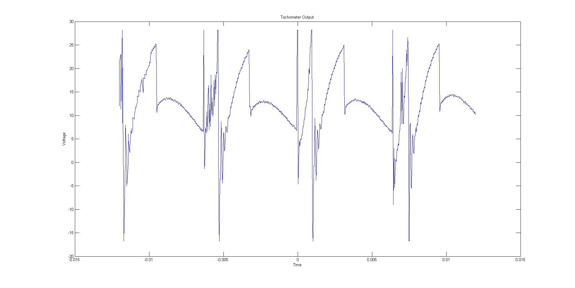
The input waveform:
I've unfortunately deleted the original waveform files I had saved from my Rigol 1052E but I'll remake them as soon as I can. (EDIT: Added pics) The basics of the waveform was that it was a +-20Vish super noisy pulsing waveform. The main challenge I faced was making this into something the Arduino can read while still preserving the data integrity. Simulation tools were used in order to achieve this.
The Filter:
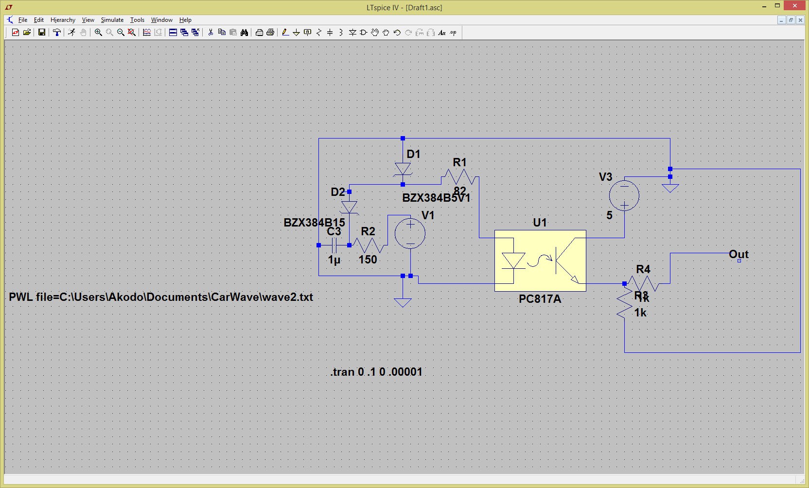
This is the current revision of the filter. It takes the waveform in from the car and converts it into a 5V square wave. The intention of the first RC stage is to reduce some of the noise coming from the input. After this, the two Zeners are for first truncating the waveform to remove any false positives and then cut off the voltage at 5.1V to protect the opto-isolator from any spikes in voltage.
Discussions
Become a Hackaday.io Member
Create an account to leave a comment. Already have an account? Log In.