Close
0%
0%

3 Axis Gimbal

A 3 axis gimbal I designed for a test fixture at work.

Similar projects worth following
The original has only printed corners and machined sides due to our printer not being large enough to print all the sides. I did a test print of the bearing hole in ABS with a 0.4mm nozzle and standard Fine settings in Cura 2.6 on our Ultimaker 2 and the bearing was a nice press fit.

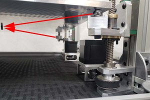
Stainless steel pins are used for the locking mechanisms. They were machined with grooves for 4 C-clips but I have listed external push rings which will work although you will only be able to install 3. Be sure to round off at least the one end of the pin so it will slide easily into the locking hole. Stick a block under the outer locking ring plate of sufficient height for the locking pins to clear the next ring by about an 1/8" and slide the inner locking ring up against the wall and seat in place with the external push rings. We reamed the locking pin holes to 0.128" and got a nice sliding fit which would stay back out of the way when in free swinging mode.

We used slip rings from Adafruit (https://www.adafruit.com/product/1195) to get power and data into the center.

Standard Tesselated Geometry - 16.68 kB - 07/28/2017 at 15:49

Download

Standard Tesselated Geometry - 72.54 kB - 07/28/2017 at 15:49

Download

Standard Tesselated Geometry - 50.18 kB - 07/28/2017 at 15:49

Download

Standard Tesselated Geometry - 30.45 kB - 07/28/2017 at 15:49

Download

Standard Tesselated Geometry - 77.04 kB - 07/28/2017 at 15:49

Download

View all 23 files

View all 11 components

  • 1
    Basic build

    Assemble from the inside to outside (inside, middle, outer, outer #2). I used a washer on both sides of the joints for extra support. Use extra walls when printing the base so you can tap the 1/4-20 holes.

View all instructions

Enjoy this project?

Share

Discussions

Similar Projects

Does this project spark your interest?

Become a member to follow this project and never miss any updates