 Spencer
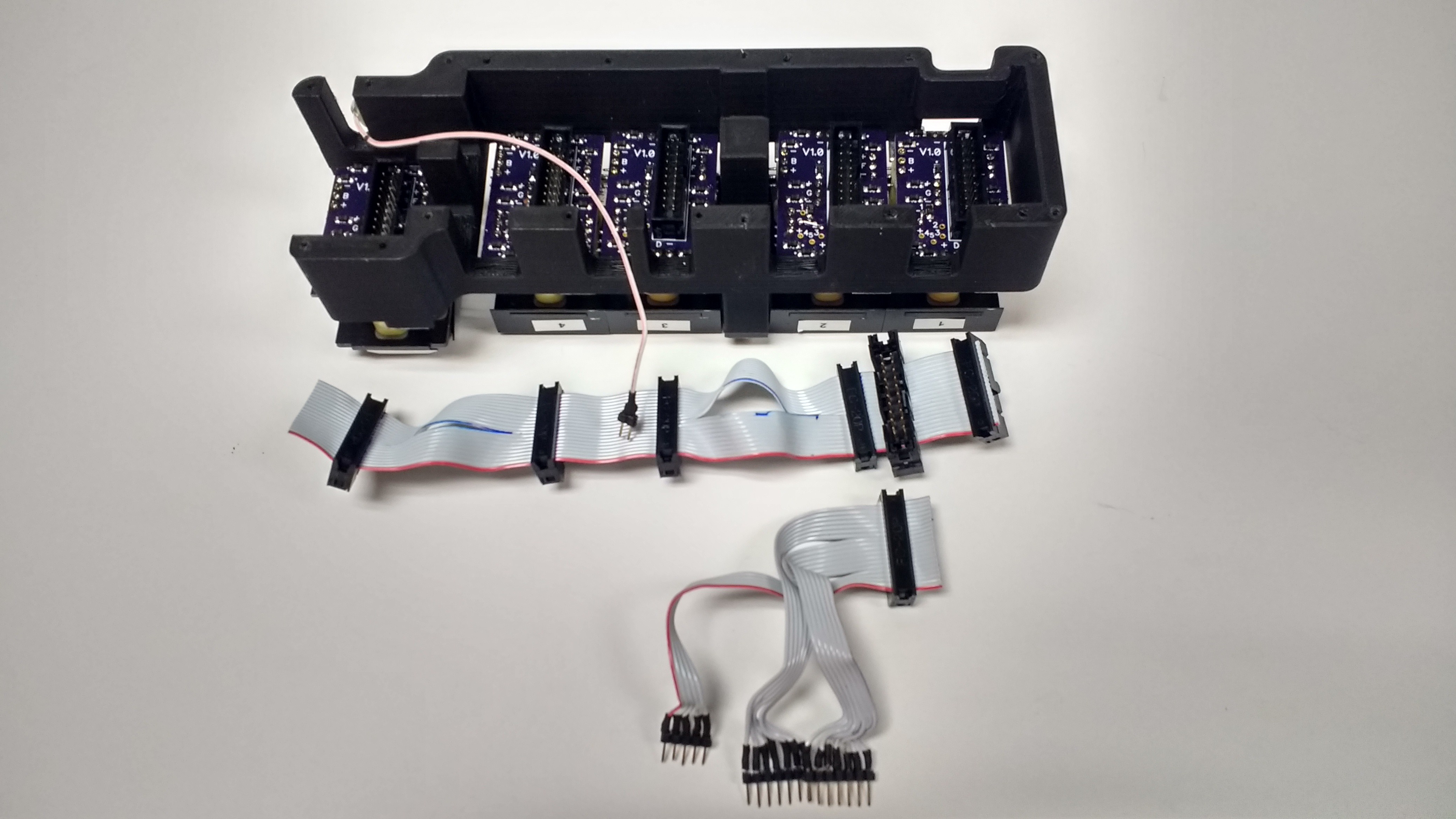
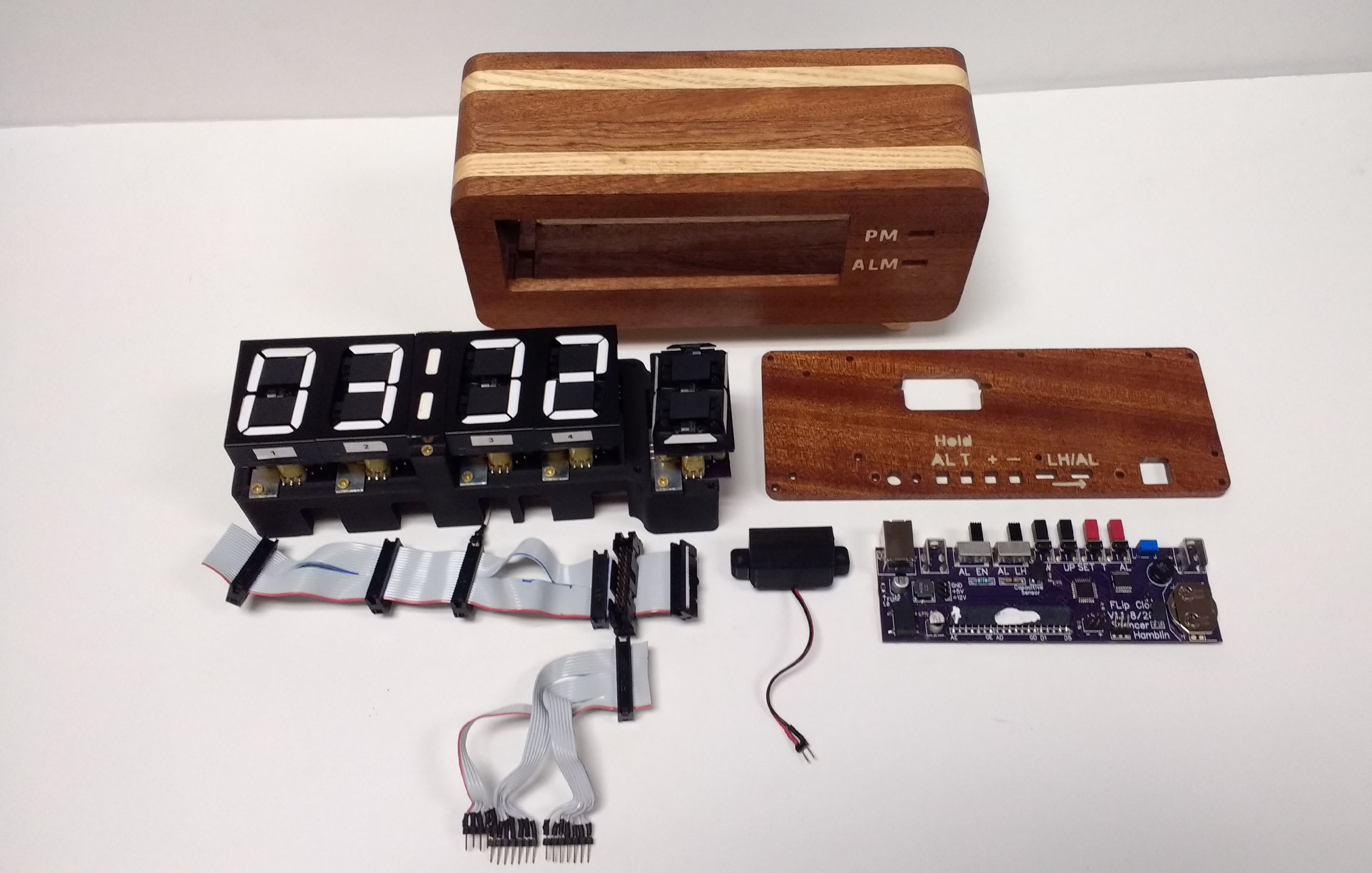
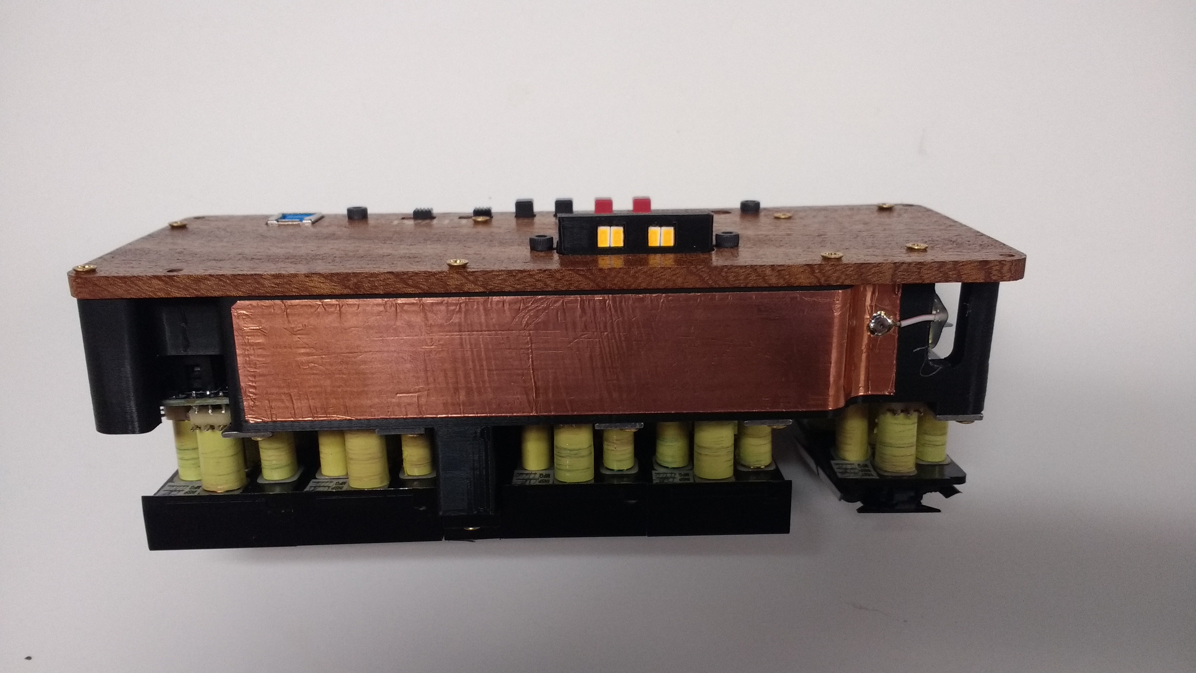
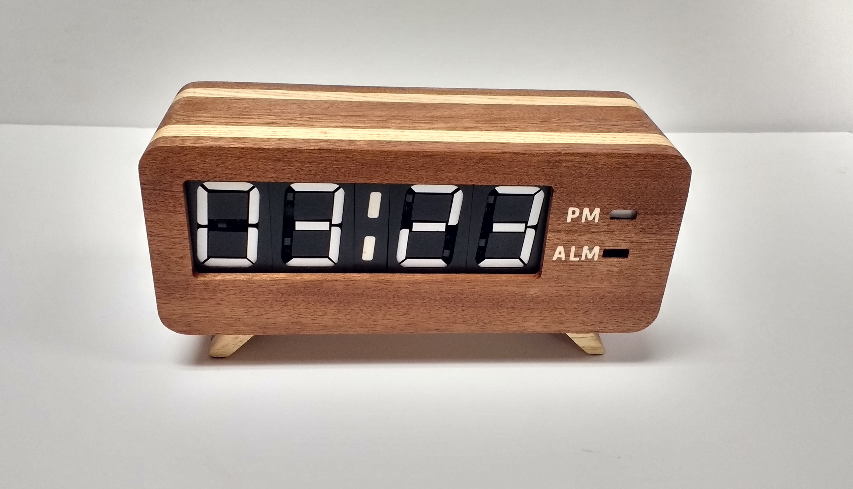
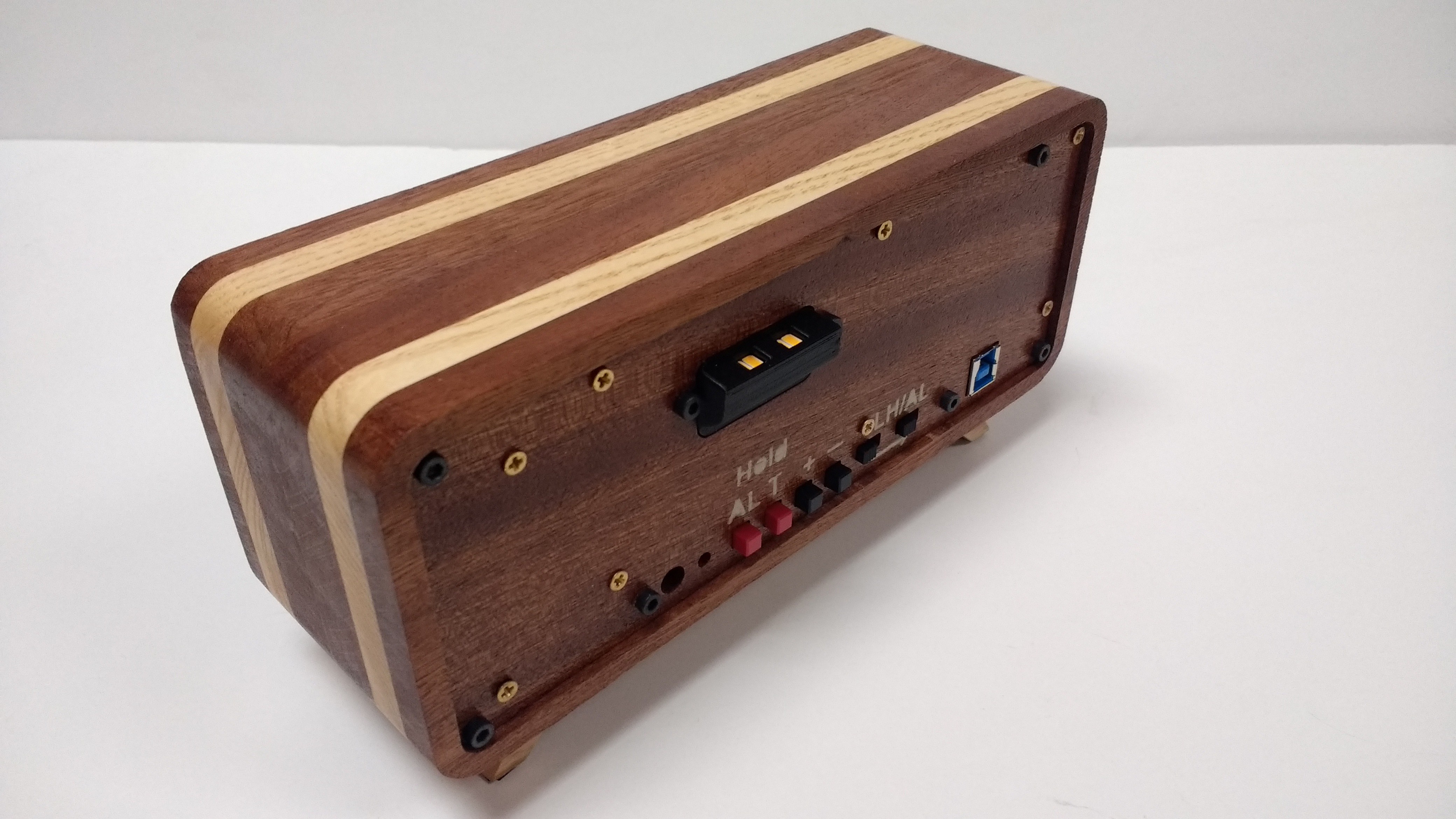
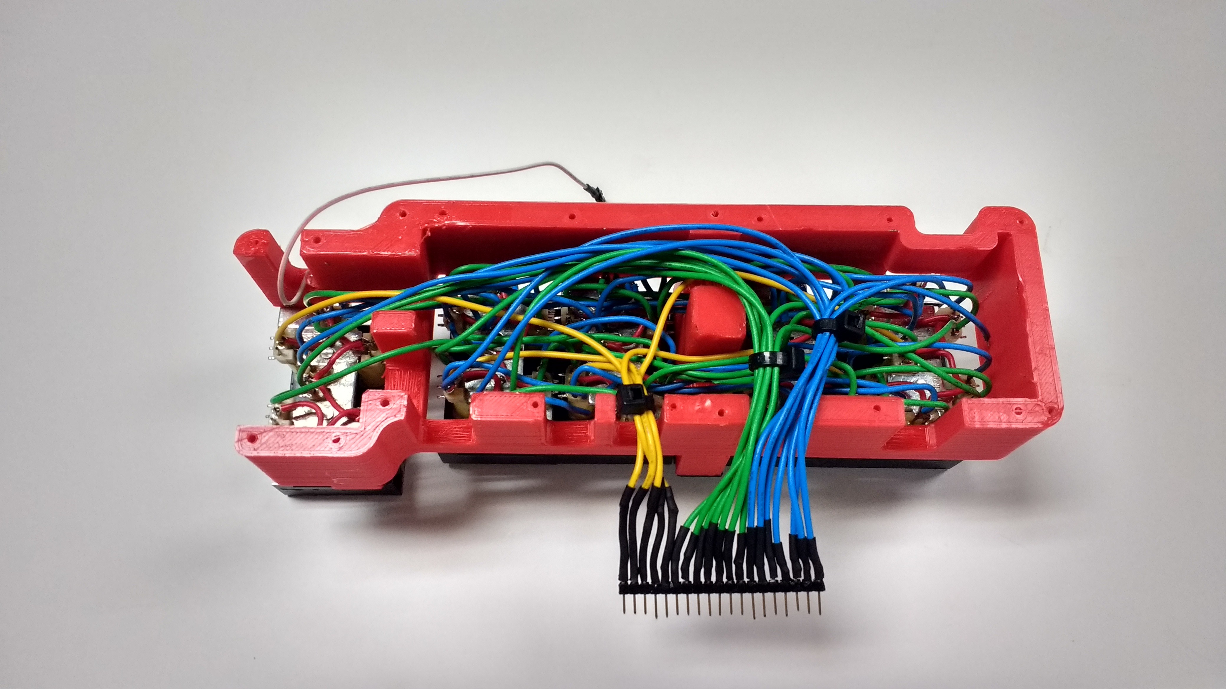
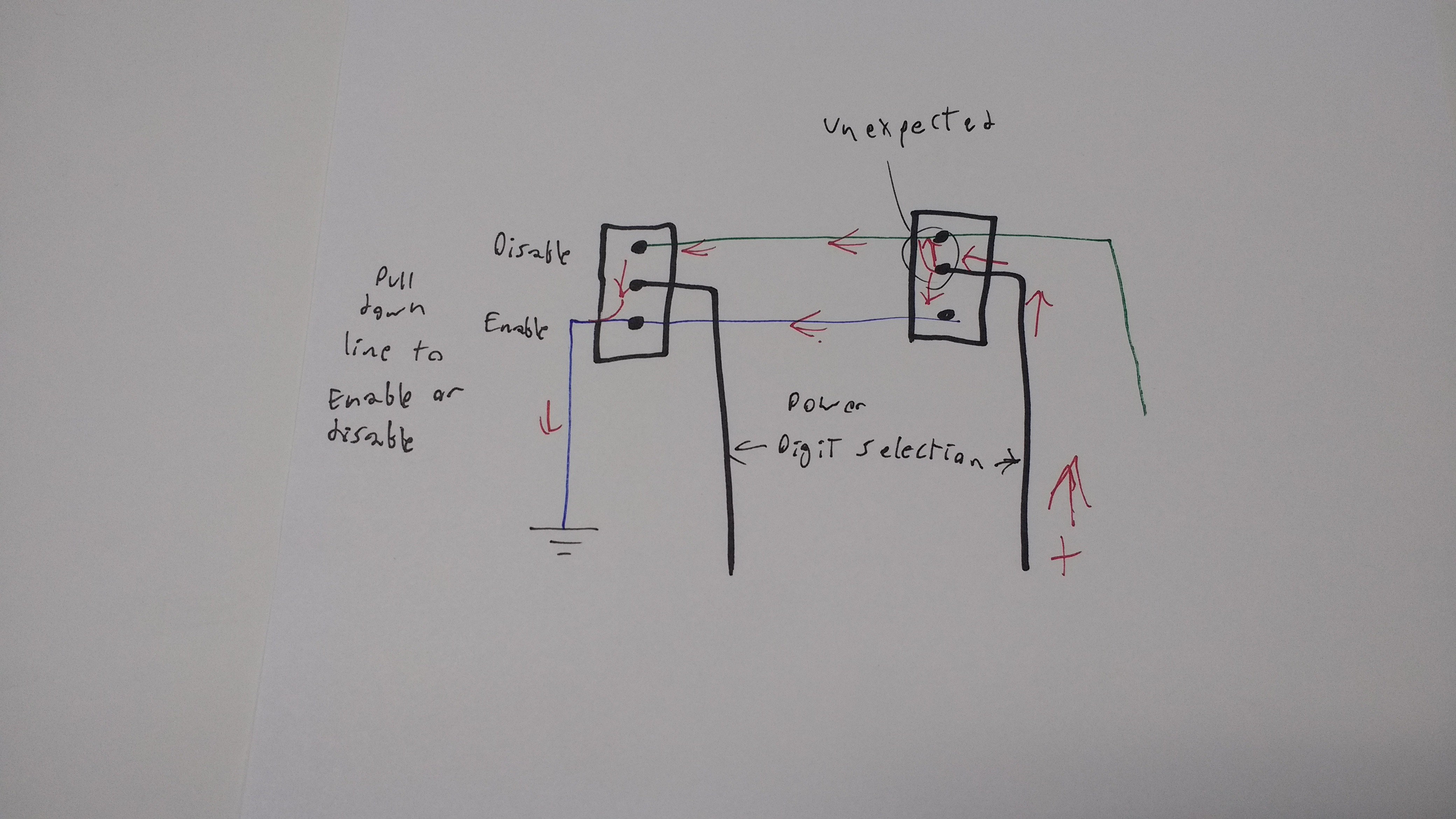
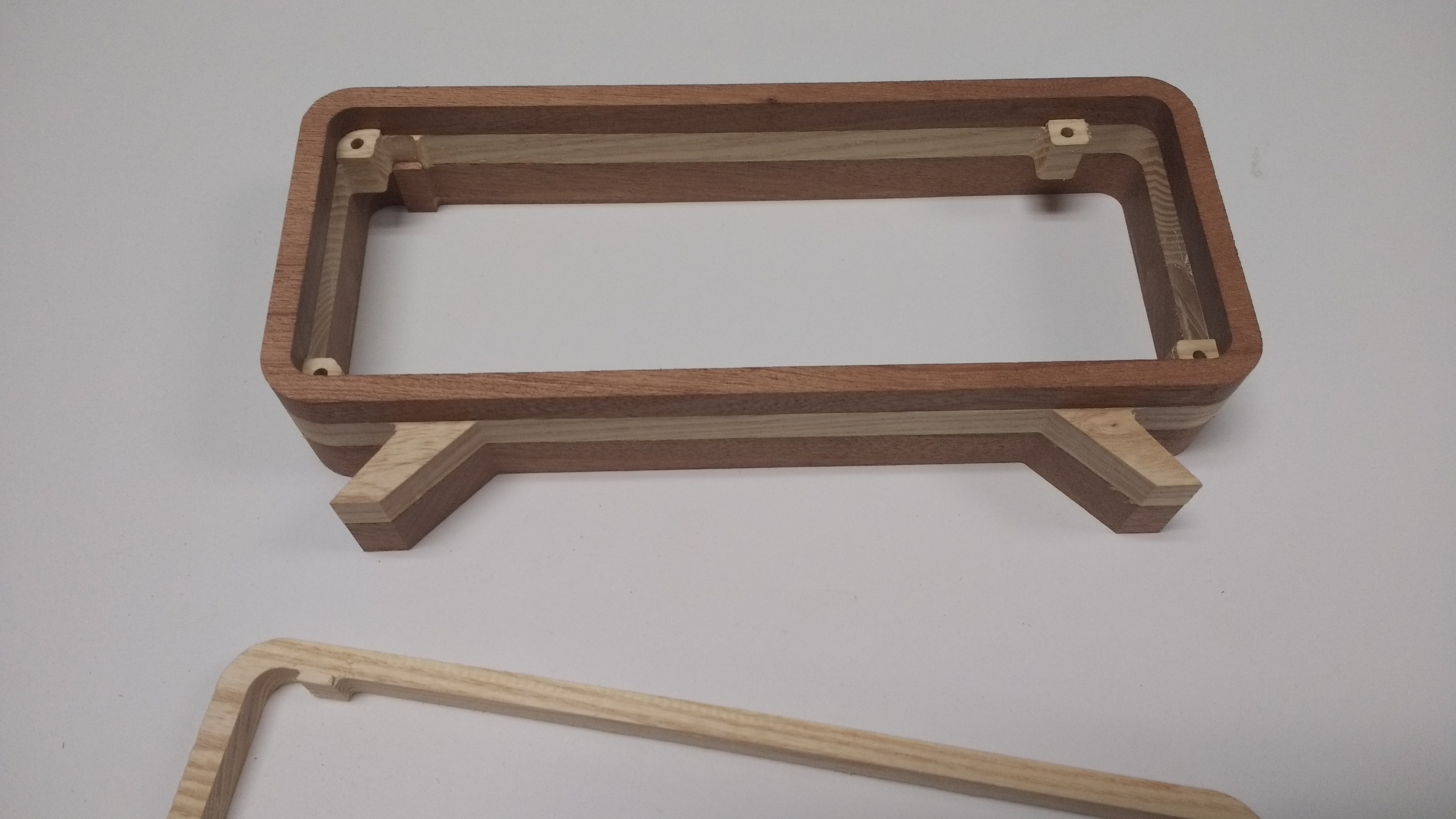
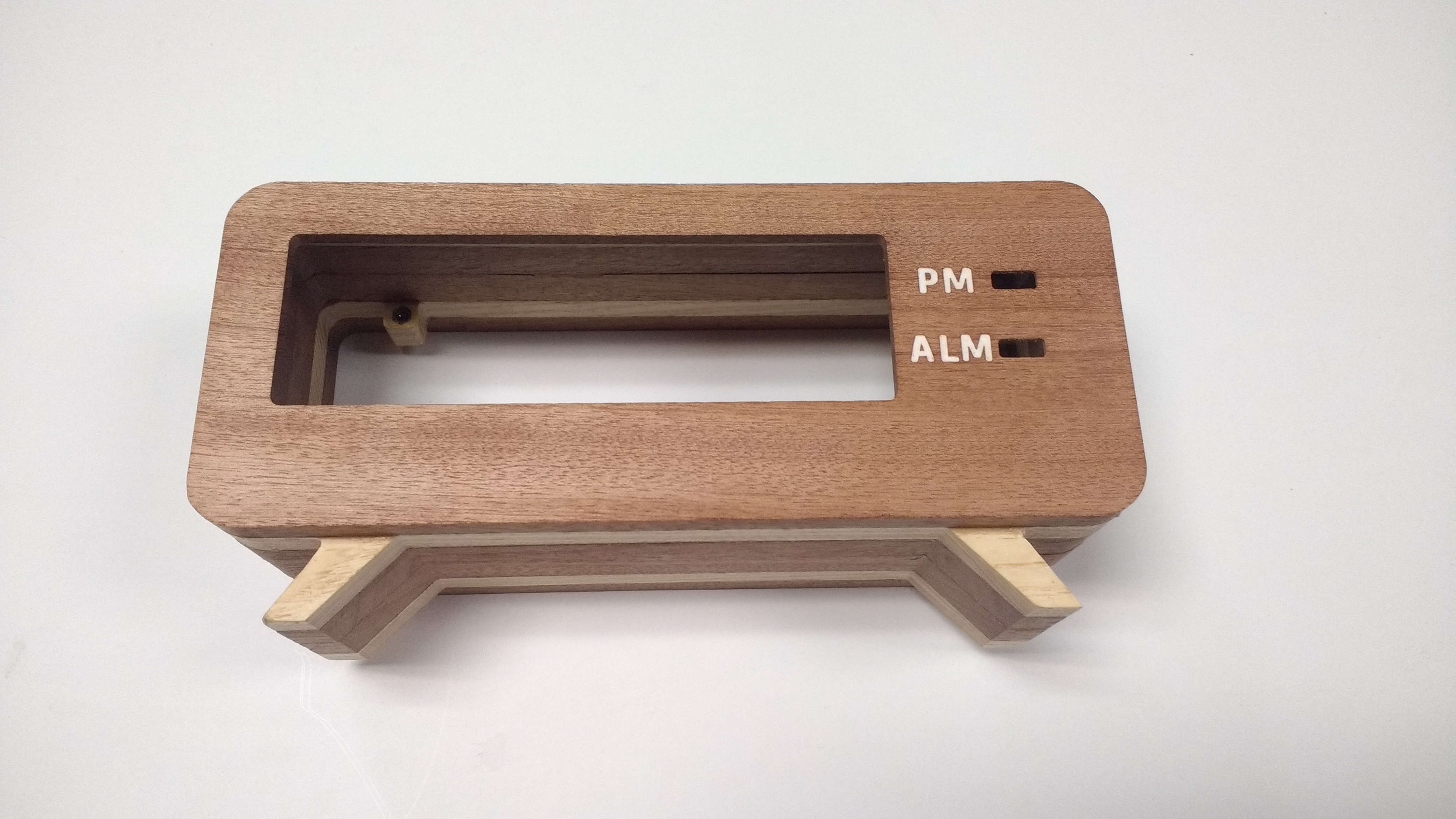
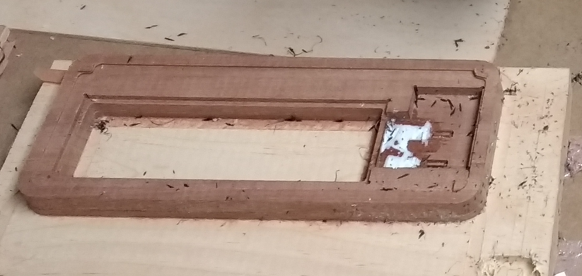
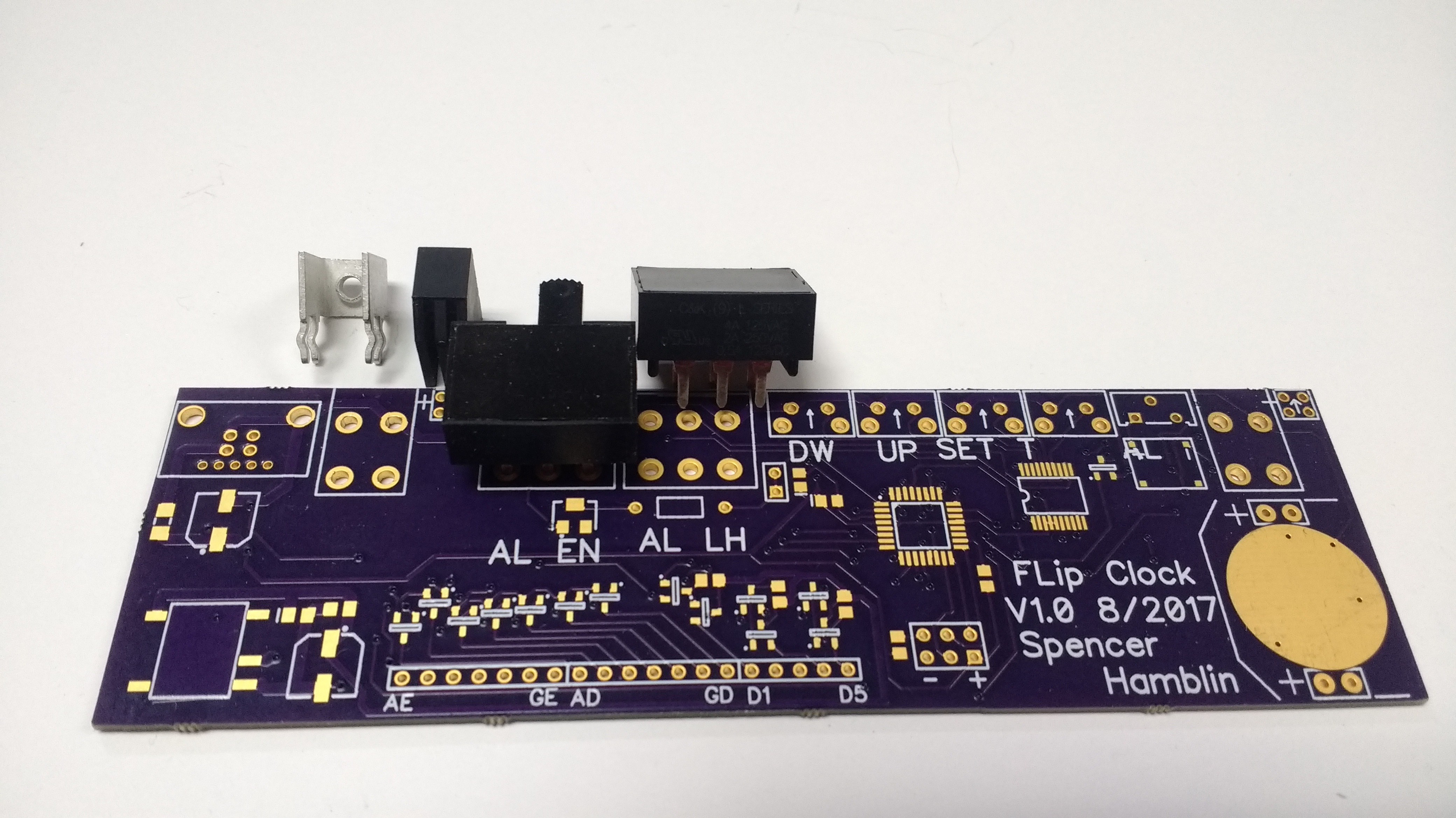
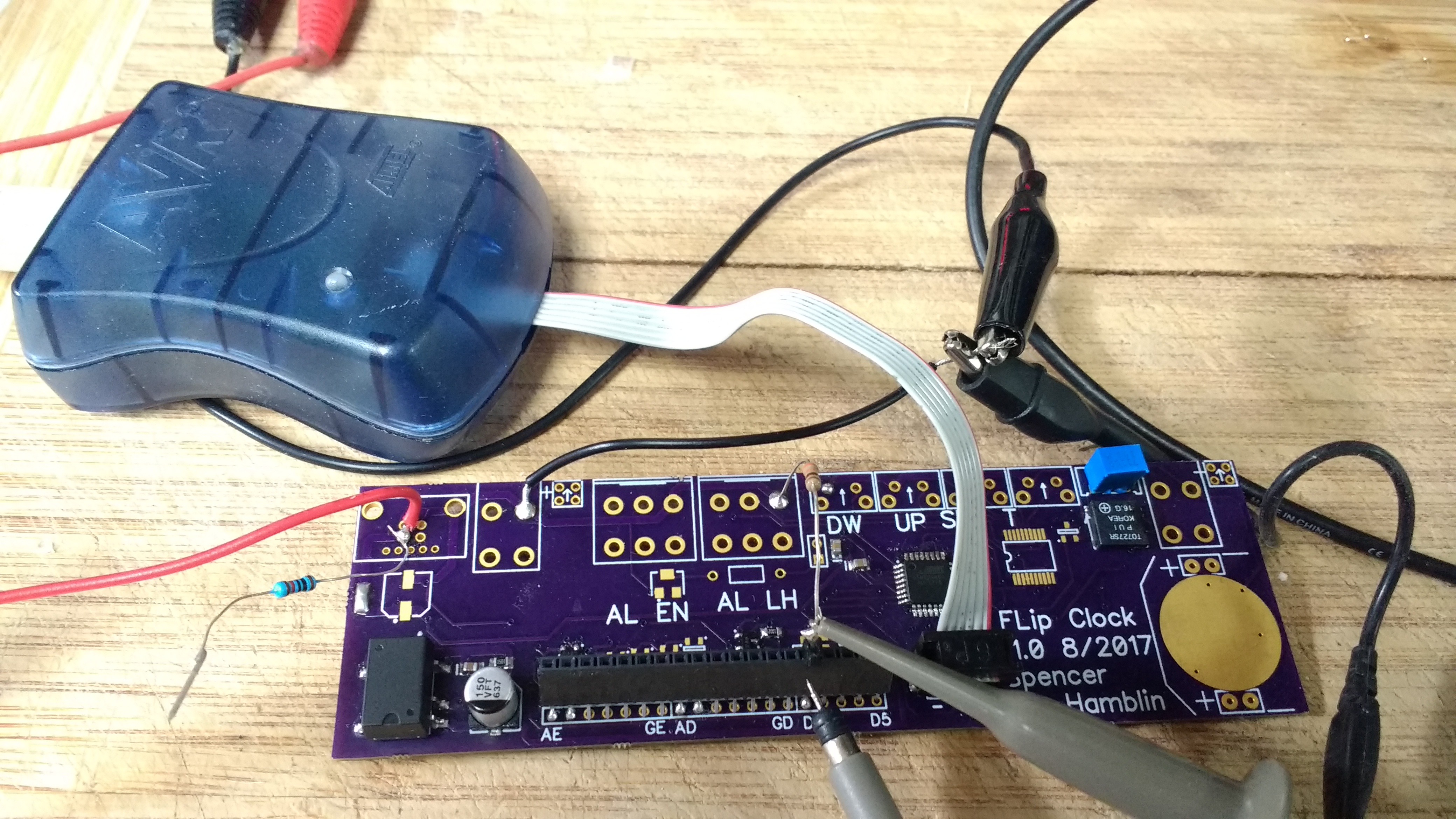
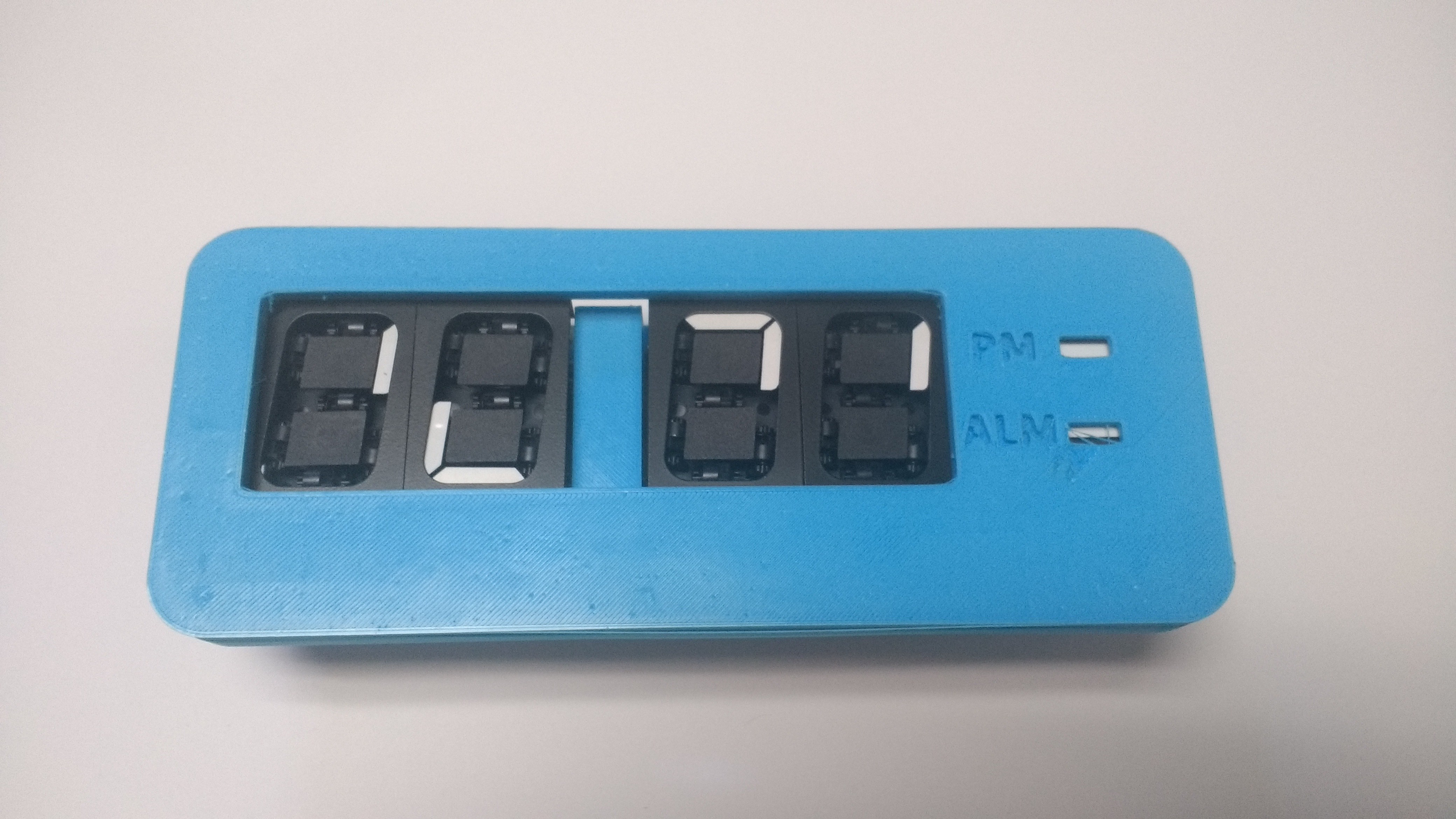
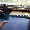
This is a flip dot inspired clock. Using vintage 7 segment flip dot modules I plan to create a stylish clock. However flips dots have unique challenges when it comes to driving them. Some features of the clock will also require serious thought. To maintain the look of the clock I want to keep the top free of buttons. However I still need a way to shut off the alarm in the morning. To do this I will have to use capacitive sensing. The wood working it's self presents a modest challenge.
Hopefully this will be a quick, well polished project. Stay tuned for updates! Thanks for looking, comment below if you have any questions.


 zaphod
 Atheros
 Walter
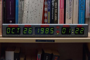
 Stephen Holdaway
Geiles Projekt, Leider hab ich. mich bisher nur mit Arduino beschägtigt... Gibt es eine Möglichkeit dafür? Habe nämlich 4 solcher Displays und würde die gerne mal ans laufen bringen. LG