 Spencer
Well after much waiting the new display adapter boards came in. This time each enable or disable pin has a diode preventing back feeding. I also redid the wiring and went with ribbon cables this time. The hand wiring was tedious to say the least and unreliable.
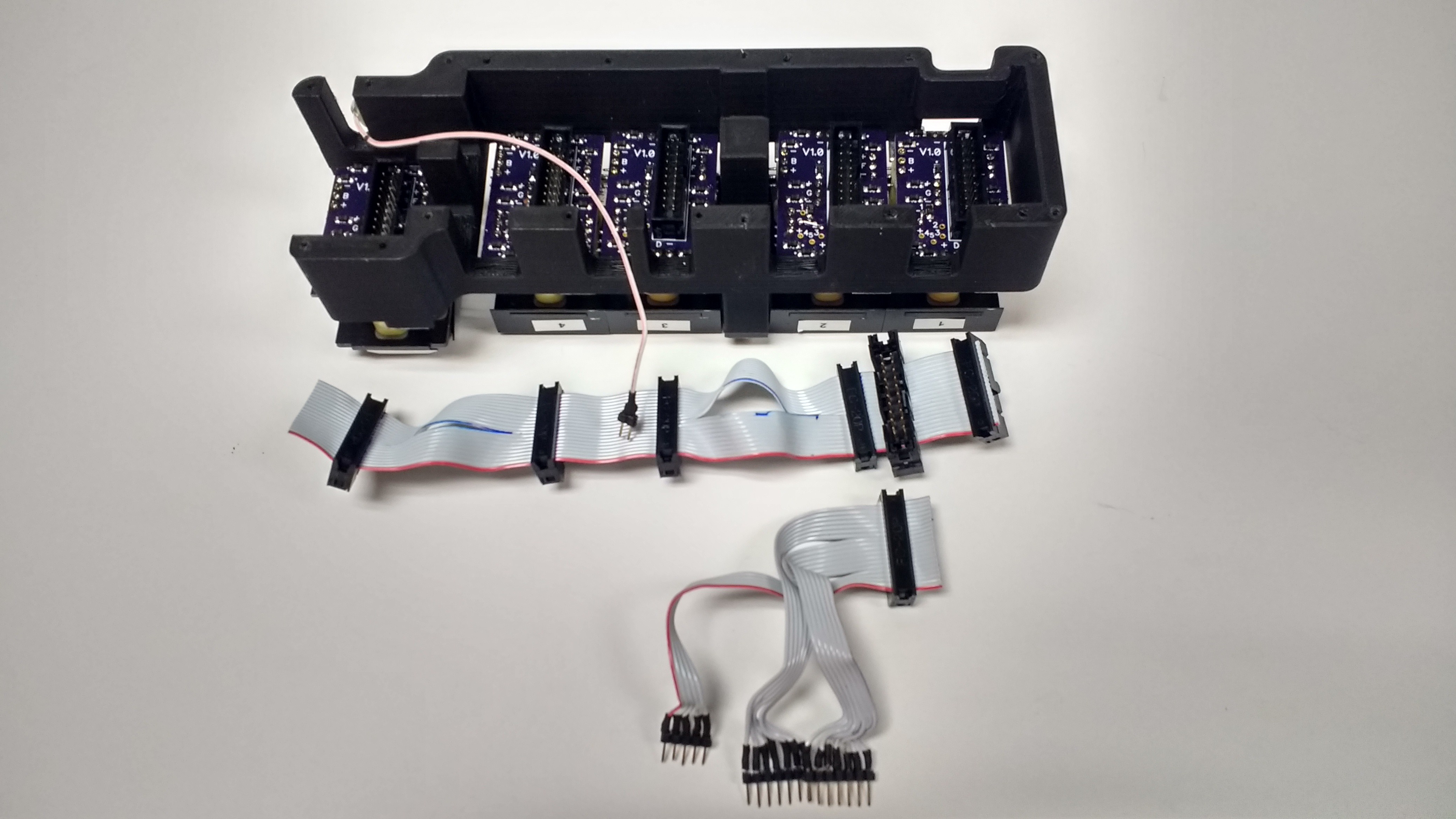
With a proper crimping tool ribbon cables are a breeze. The two cuts you see in the cable allow it to be routed along the support posts on the frame. Then the lower cable simply attaches on and breaks out the connections to the main board. Pretty slick.
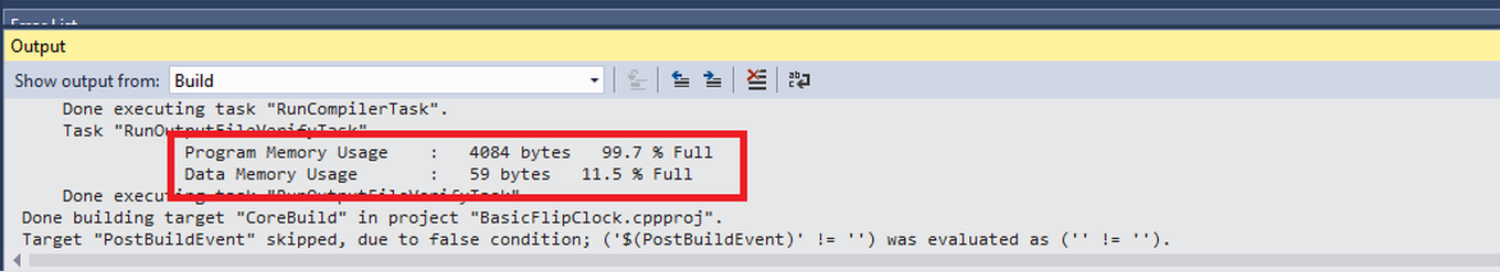
With the board wired up properly time to work on the display code! Finally I get to see this thing tick. For the code I used an event loop based system. The clock iterates though a loop every 10-20 mS. This might not be the most elegant way but it worked well for the features I wanted. For most of the buttons holding them down triggers and alternate function, the event loops lets me easily keep track of how long every button has been held down. However that was a major gotcha that I ran into that almost derailed the project. I almost ran out of space in the 4096 byte chip. I ended up doing some serious code optimizations. I came in at 4084 bytes used out of 4096. I did get all the features in that I wanted so I just barely squeaked by!
Alright I'm getting close to the end here! Time for final assembly! One of my design goals was to have the project breakdown easily. Judging by the picture below I'd say I accomplished this goal.
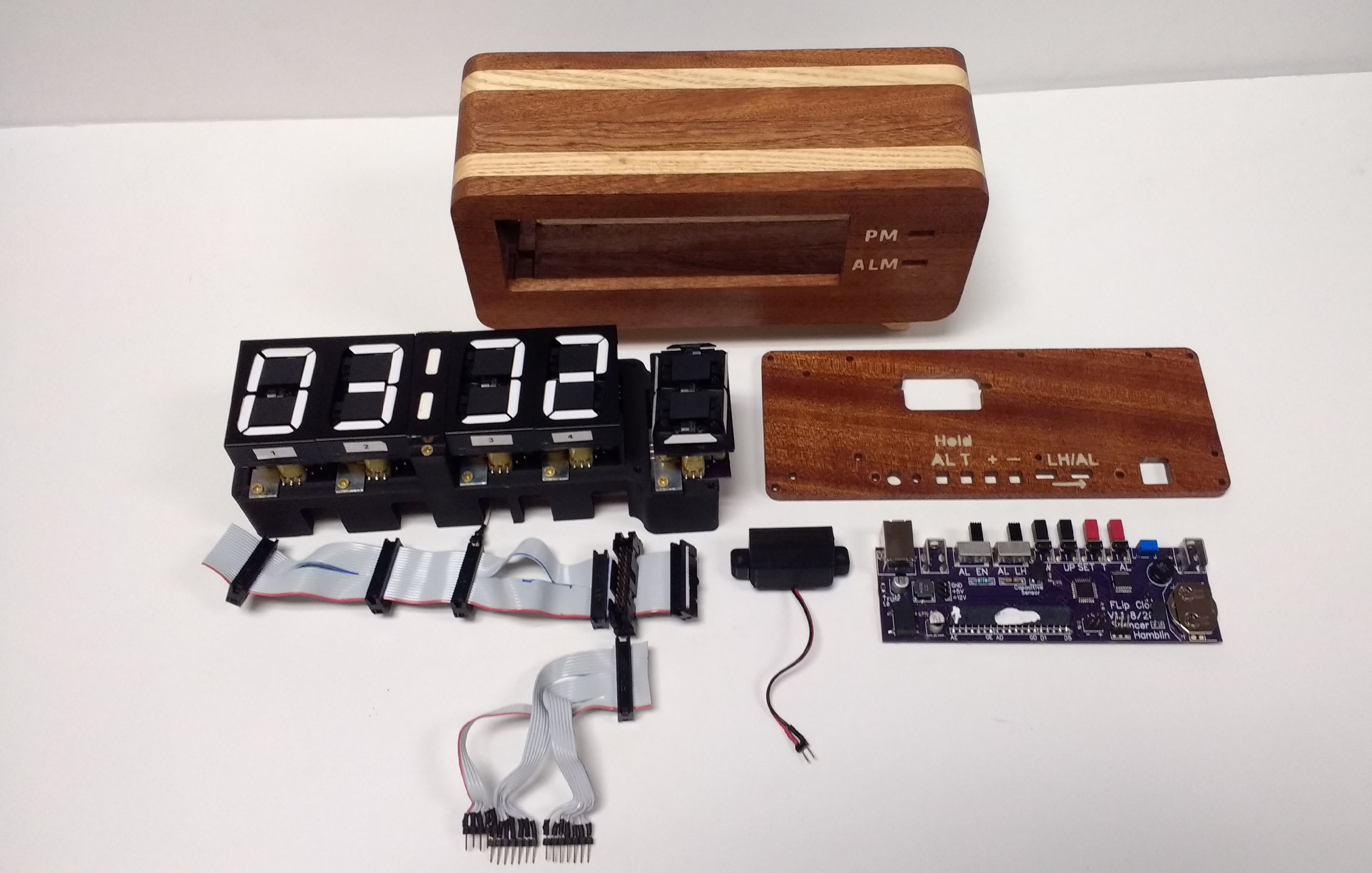
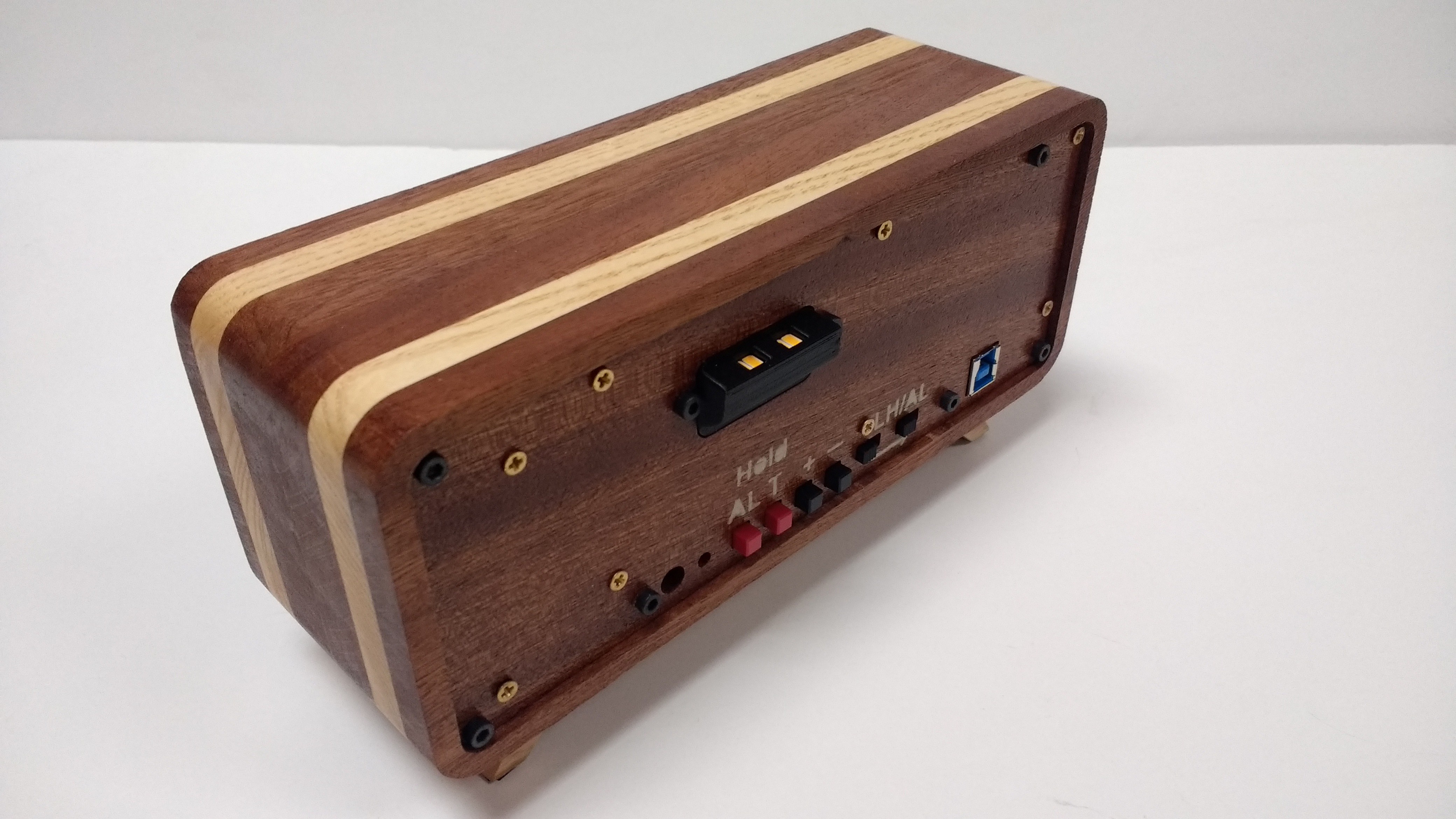
Once built the clock splits up into two main parts. The main frame the core. The core pictured bellow inserts into the frame very nicely. It's held together with 4 3M bolts. I managed to get a very tight fit, only a few thou of wiggle room on each side. Looking at the top of the core you can see the capacitive sensor. The copper tape acts as a hand sensor to tell when your touching the top of the clock. This works as the snooze button and a way to toggle the light. The light prominently displayed in the black part sticking out the back is supposed to simulate the sun making waking up easier.
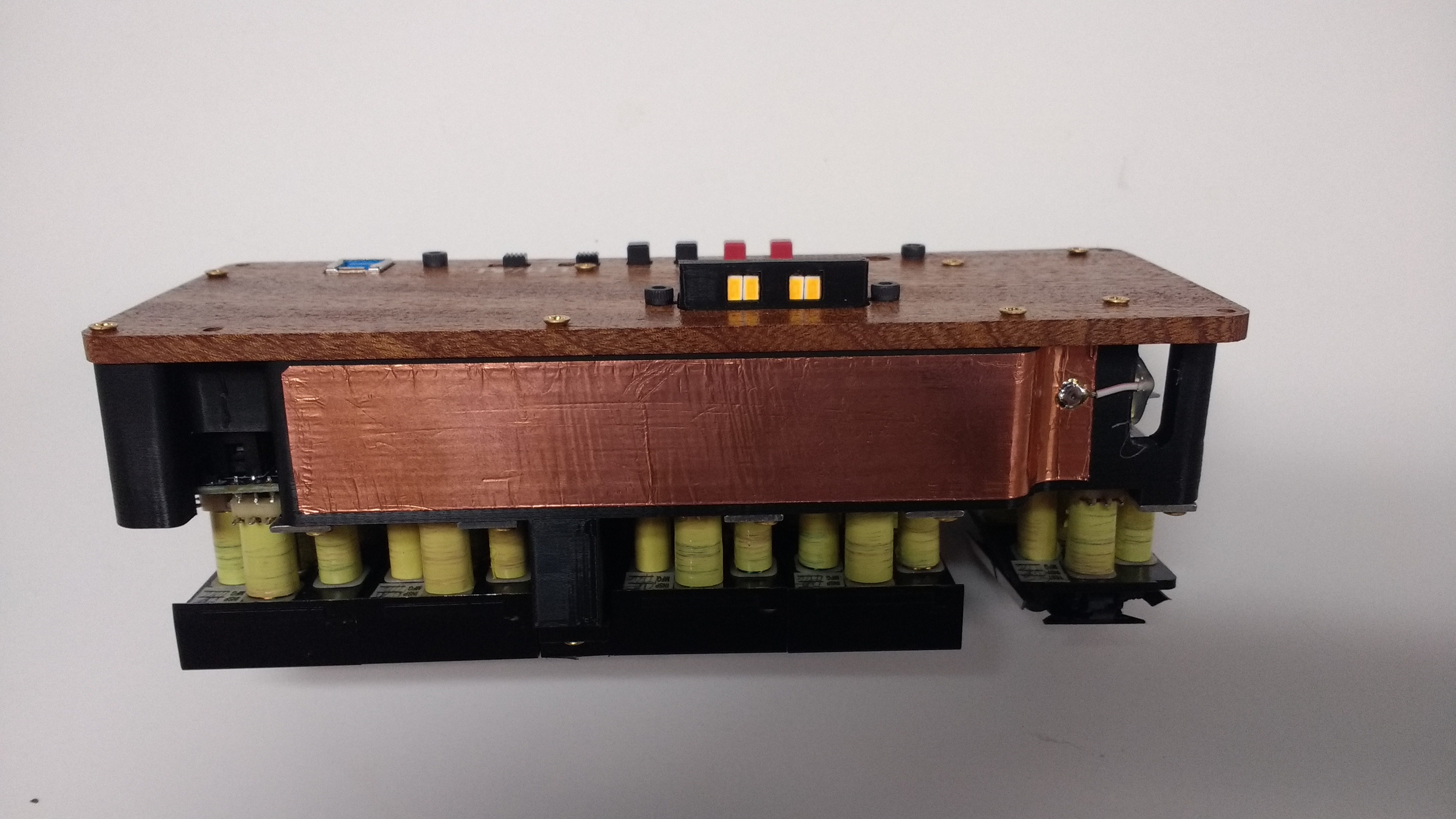
With the core explained time to put it all together!
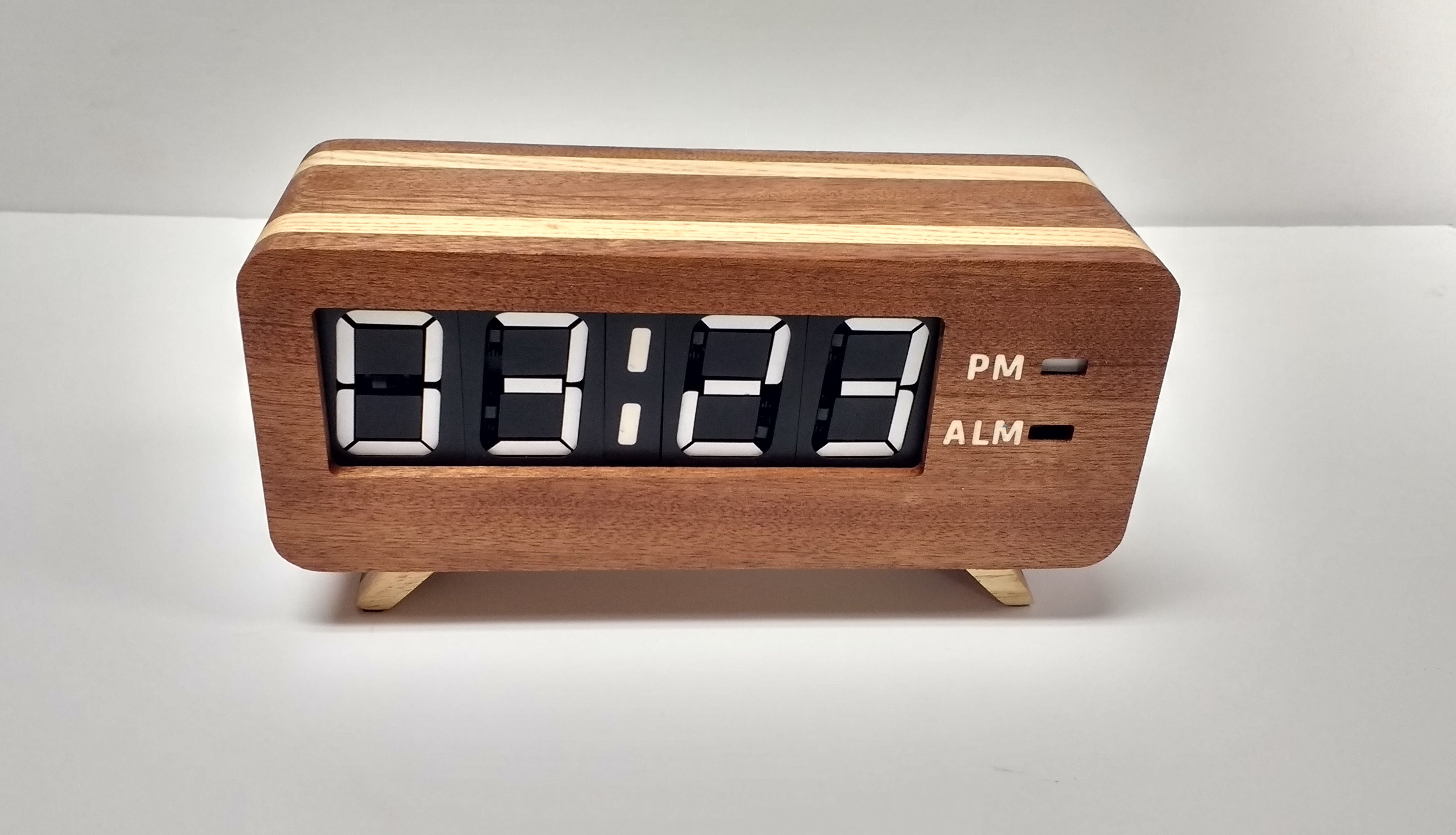
And oh man what a striking clock that is! It turned out just like the 3D renders, and after all this work it had better look good! My only real regret is using a printer style usb cable. They tend to be really stiff and I had a hard time finding a flexible one. In the future I think I'll try usb C as a power cable.
Discussions
Become a Hackaday.io Member
Create an account to leave a comment. Already have an account? Log In.