 Pratik Makwana
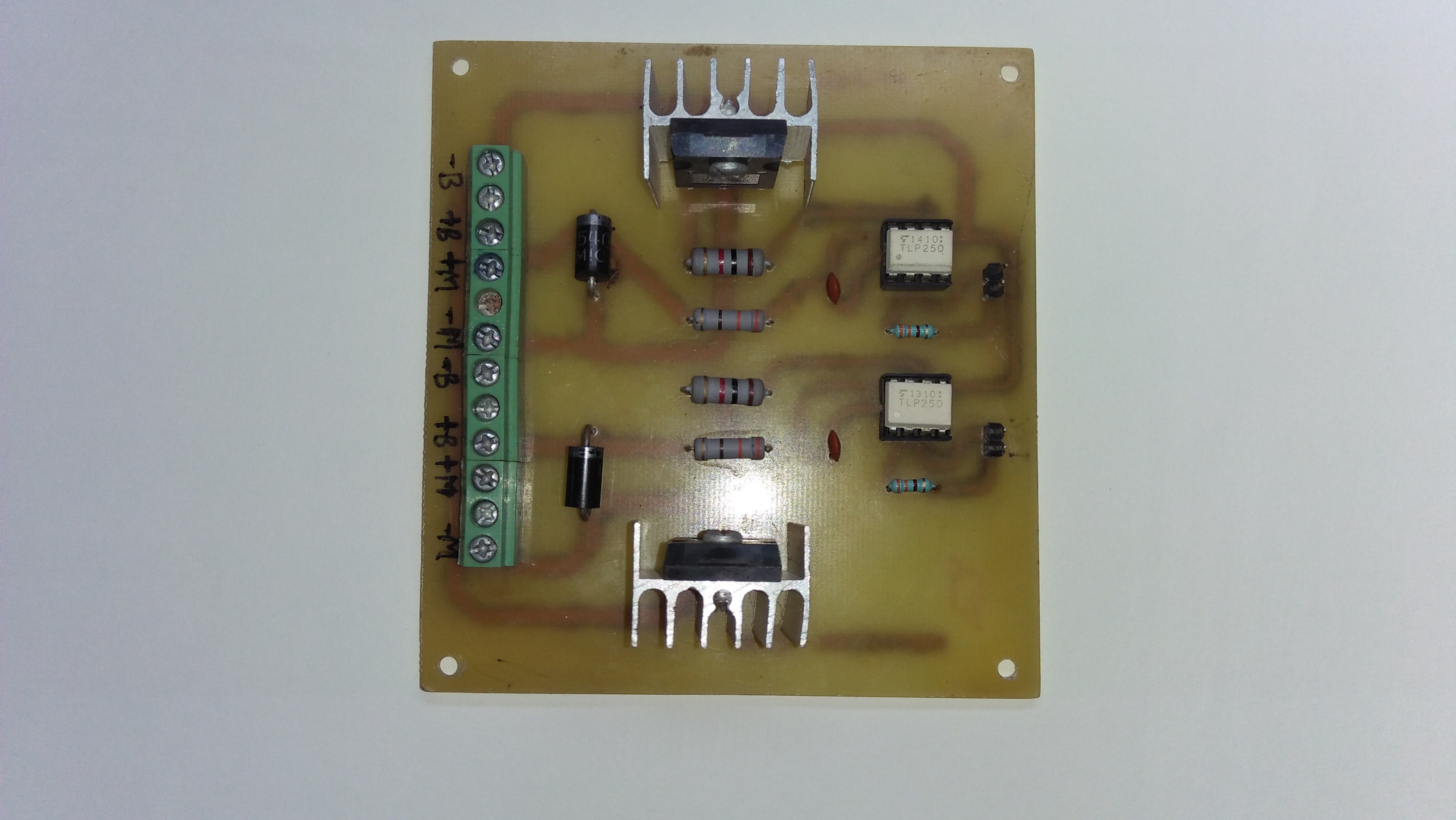
In this Project, I will show you how to make PWM Controller. I'm using the laminator for the toner transfer method.
What things you will need:
- Copper - clad board (Dual Layer)
- Ferric Chloride (FeCl3)
- Acetone (Nail polish remover)
- Glossy Paper
- LASER Printer
- Marker Pen
- Scissors
- Plastic container
- Sand paper
- Safety gloves
- Latex gloves
- Saw - For copper board cutting Laminator or iron
Let's Do it...
Step 1: Designing of the Circuit
![]()
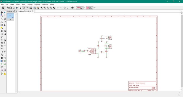
Design schematic diagram in EDA tool (PCB Design Software). List of EDA Tools (PCB Design Software):
- DipTrace
- EAGLE PCB Design
- Kicad EDA
- Express PCB
- Proteus PCB Design & Simulation software
- Altium Designer NI Multisim
You can select any one of them. I prefer EAGLE PCB Design Software.
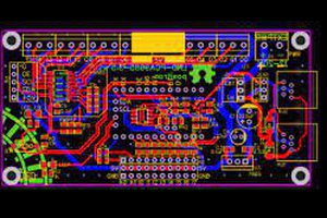
Step 2: Designing of the PCB Layout
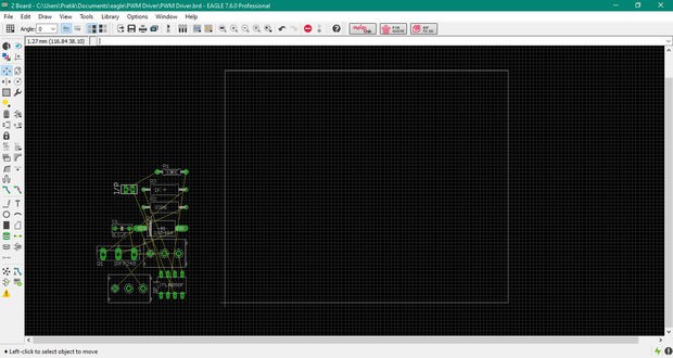
After designing of the schematic diagram, Now start designing of PCB Layout in the Eagle EDA tool (PCB Design Software). After that Take print out of PCB Layout on glossy paper.
Note:
- Use Only LASER printer only.
- Scale Factor set to 1.
Part List:
- IRFP460 - Power MOSFET
- TLP250 - Gate Driver
- 1N5403 - Diode (3Amps)
- Resistors - 330E (1/4W), 330E(2W), 1K (2W)
- Capacitor - 0.1uF (104)
- Screw Terminal Block : 3 PIN (5mm)
- PCB : FR4 Glass Fiber
- Header (2.54mm) - 2 PIN
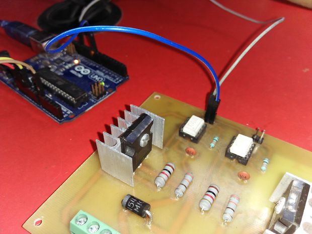
Step 3: After Soldering Process
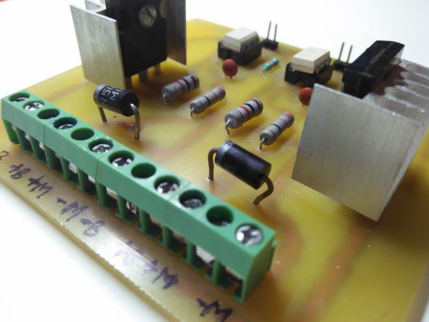
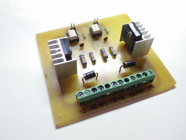
- To drives the power MOSFET I'm using gate driver IC. TLP250 IC is suitable for gate driving circuit of power MOSFET and IGBT.
- This PWM controller use for high power applications.
- This PWM controller used for the Segway.
- This PWM controller also works as PWM dimmer.
- Using this PWM controller, you can control the brightness of the LED.
- You can use this PWM controller as LED driver.
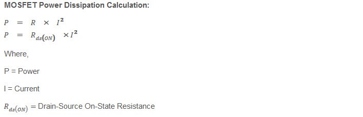
Step 4: MOSFET Power Dissipation Calculation
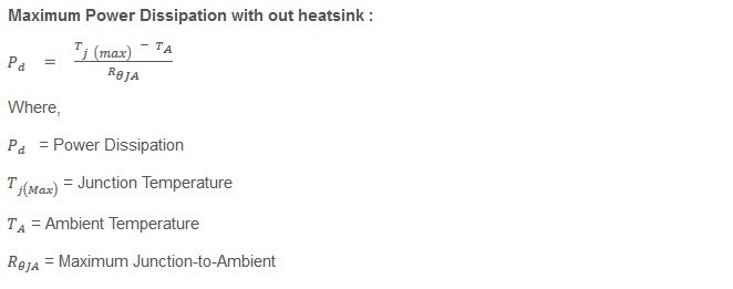
Step 5: Maximum Power Dissipation Without Heatsink
Step 6: For IRFP460 - Maximum Power Dissipation Without Heatsink
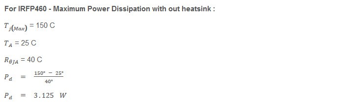
If power dissipation is more than 3.125 W, You need to put heatsink with the IRFP460 MOSFET.
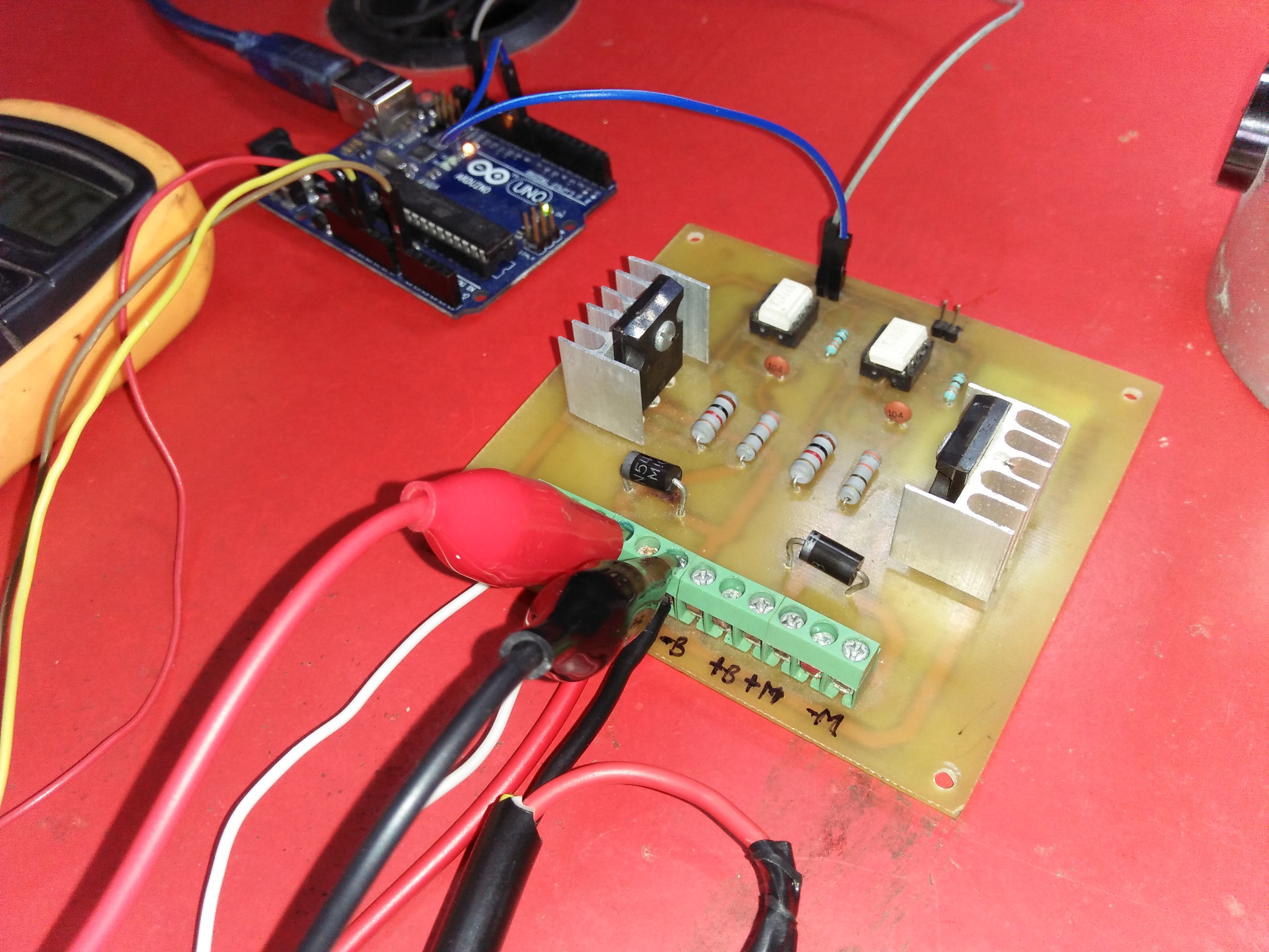
Step 7: Interfacing of PWM Driver With Arduino UNO Board
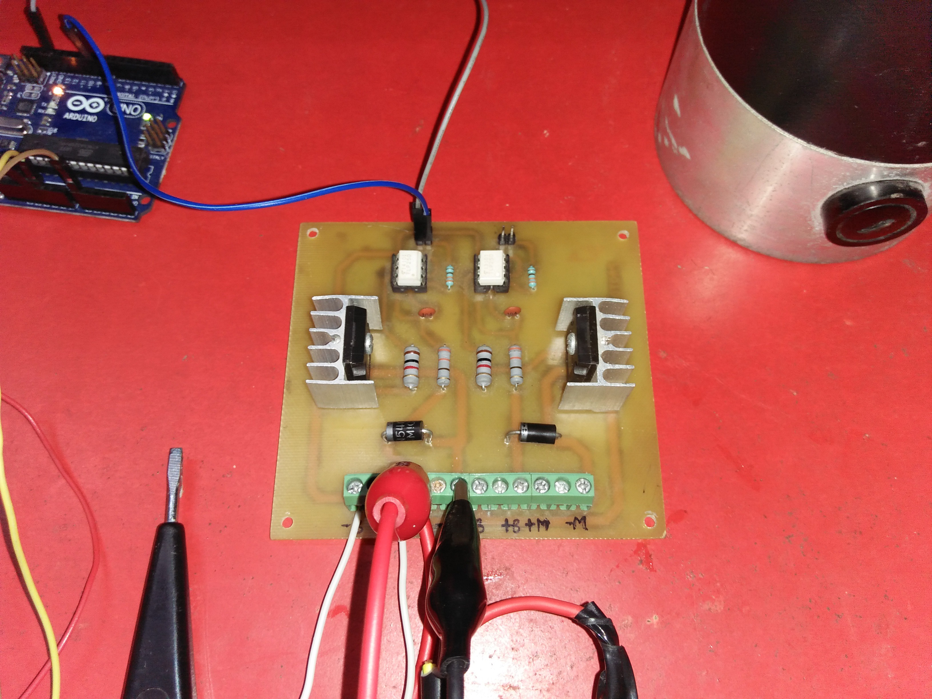
What things you will need:
- Arduino UNO board
- PWM Driver
- DC Motor ( I'm using 250 W PMDC Motor )
- SMPS ( I'm using 250 W SMPS )
- 10K Potentiometer
- Jumper Wires
Step 8: PWM Driver Use As LED Dimmer
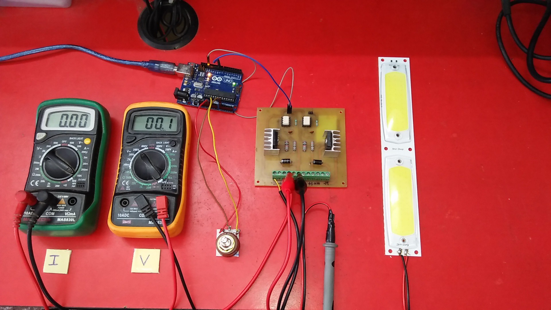
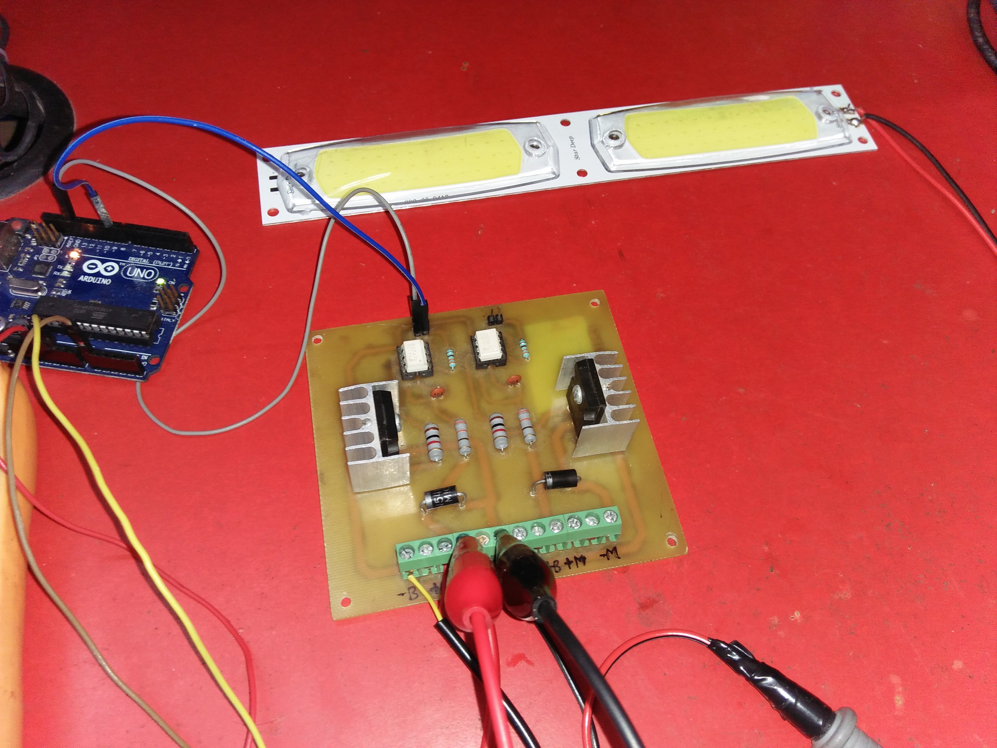
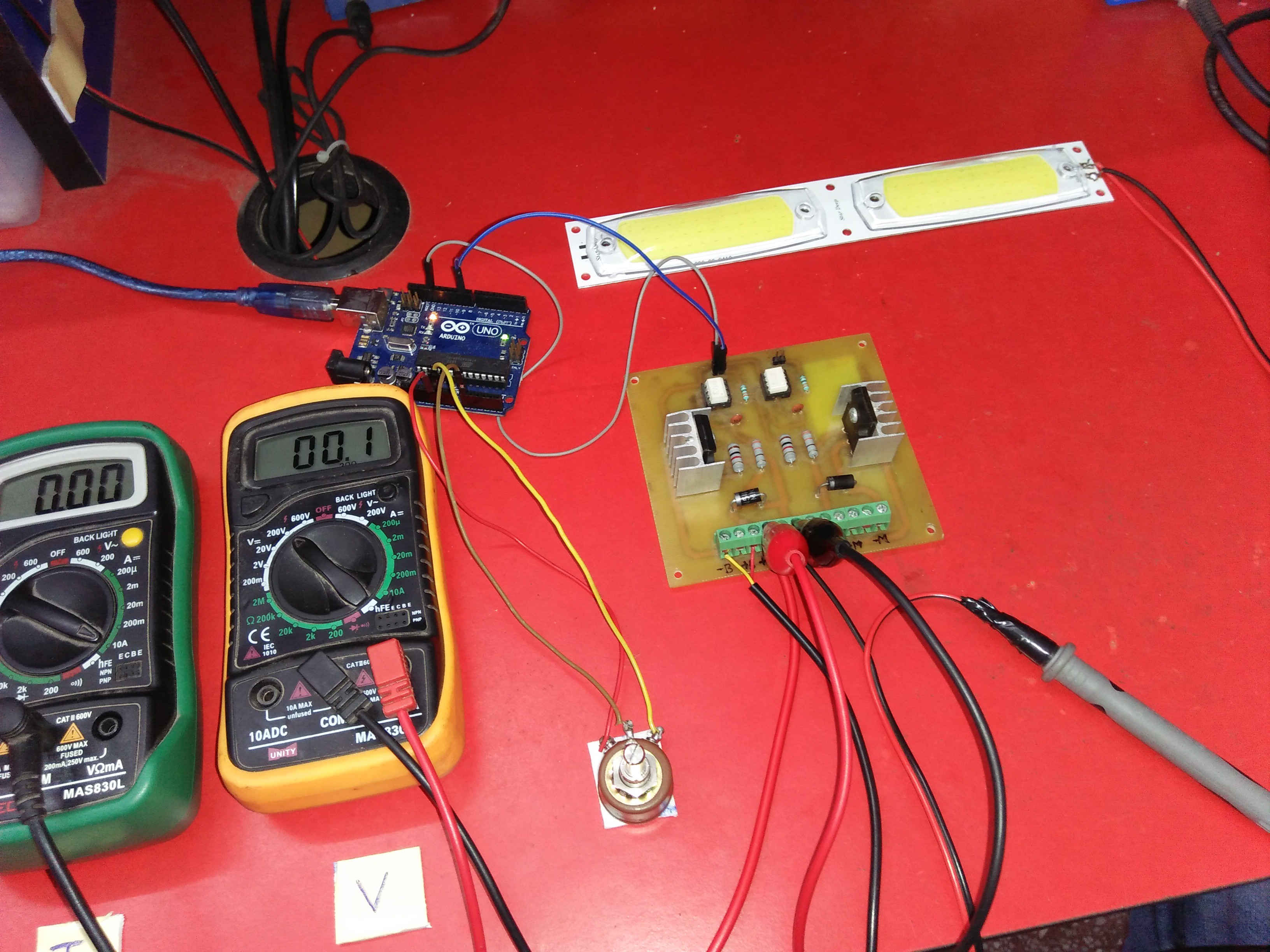
Using this PWM Driver, You can control the brightness of the LED.
PWM Controller Specifications:
- 1. Max. Voltage : 500 VDC
- 2. Max. Current : 20 Amps
- 3. Max. Power : 10,000 Watts (10Kw)
- 4. I/P Signal Voltage : 5V (PWM or Squre Wave)
- 5. I/P Signal Current : 20mA
PWM Controller Applications:
- Use for speed control of DC motor
- Use for the brightness of the LED / LED light strips
- Use for DC powered heater
- Use for tone generator
- Use for DC powered devices
This PWM controller also known as DC Drive.

 Matthew Sheffield
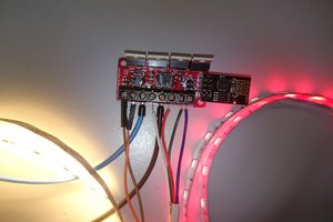
 sandy
sandy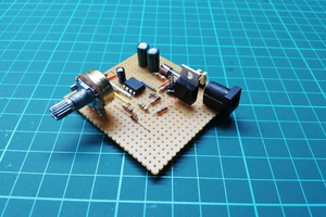
 Mrinnovative
please provide similar to arduino mega or another 8-16ch pwm signal generator side.