 Enrico
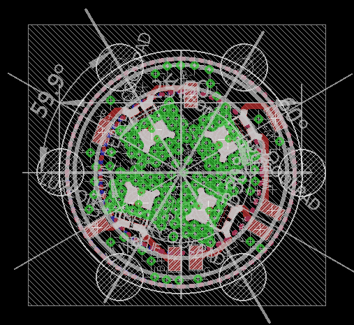
This is the first project that let me play with something different than mere fimware and PCBs, but finally a bit of boxes and acrylic planes. It is a multicolor lamp, which is developed 100% from scratch, both firmware and software, for a challenge and for seeing how things can be optimized with standard code and a new concept of power handling. The LEDs are also implemented in a 100% self-developed thermal PCB because there were no other little boards available with a given density in terms of power LEDs per square inch.
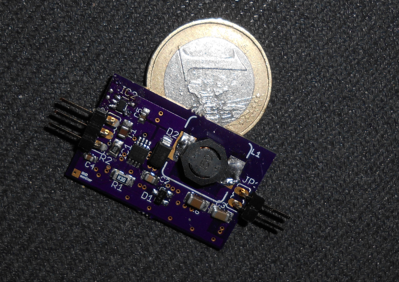
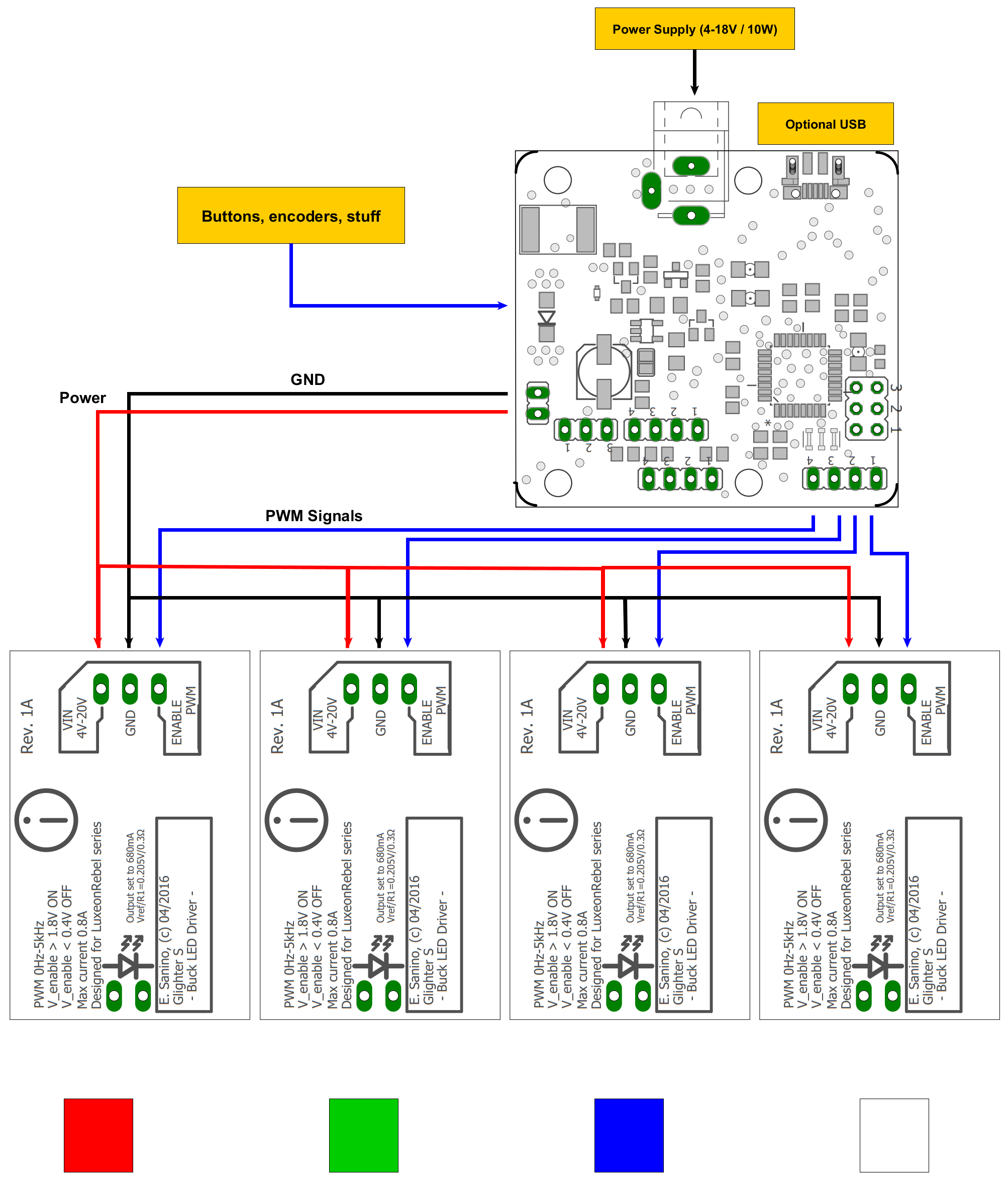
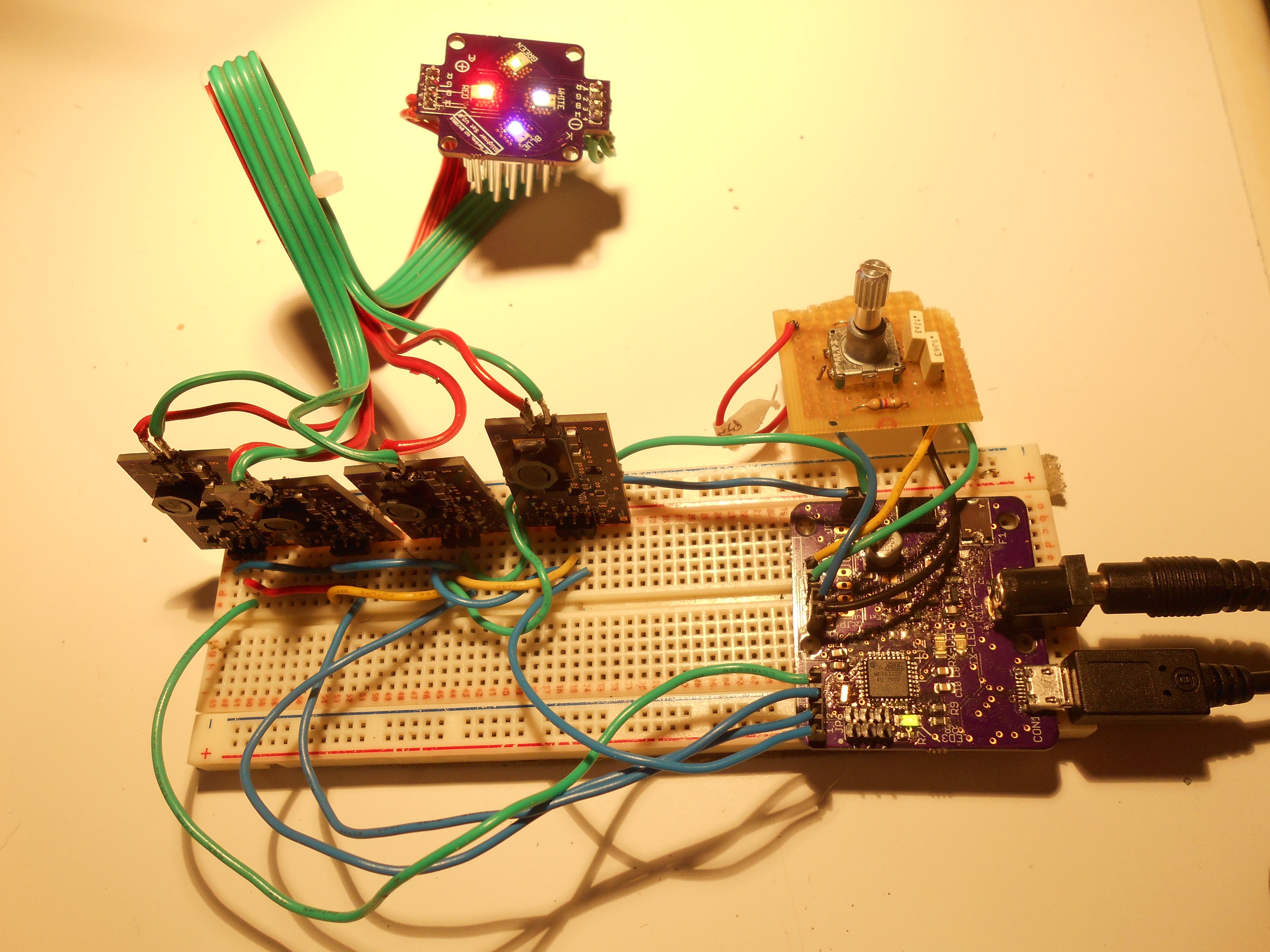
I started to build some LED drivers, then a small MCU board with a power path handler, with a built-in safety feature of power priority in made in hardware and other short circuit protections, since it is supposed to deliver more than 10W. With these loads, one need an high energy source and so a bit if protection never hurts. Those boards are Lino and Glighter.
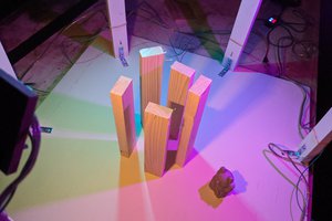
At the end, it turns out that I can use those boards together, with additional PCB for connecting the LED and with some thermal handling, to build a first draft of my desk/ambiance lamp. In the log will be present some eventual progress on how things are going.
I will keep the updates in the log as soon as I have more details ready to be published.
0%
0%
Chroma Wheeler
Reinventing the wheel on RGB lighting systems just for fun
Become a Hackaday.io member
Already have an account? Log in.
Just one more thing
To make the experience fit your profile, pick a username and tell us what interests you.
Pick an awesome username
hackaday.io/
Your profile's URL: hackaday.io/username. Max 25 alphanumeric characters.
Pick a few interests
Projects that share your interests
People that share your interests
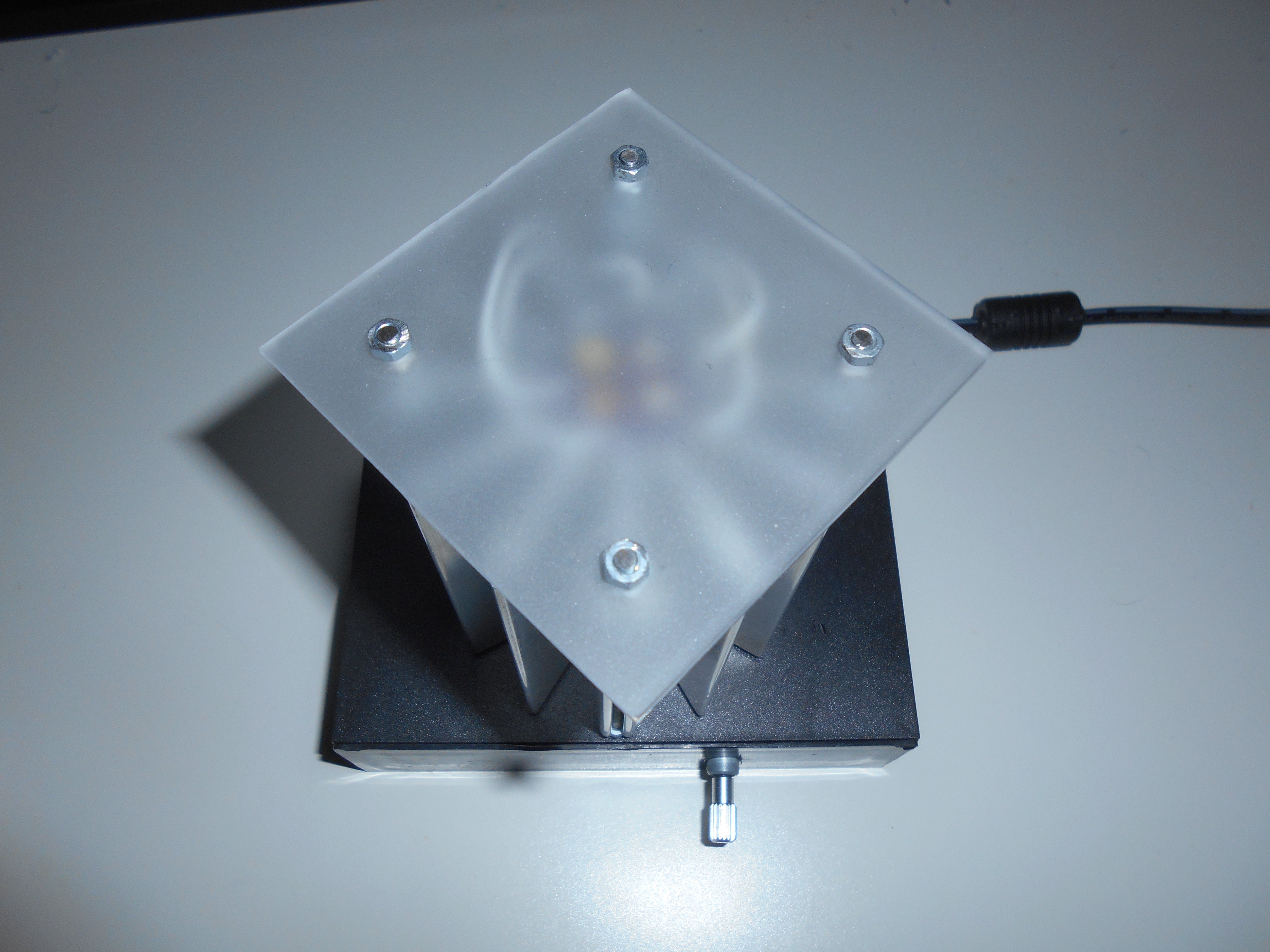
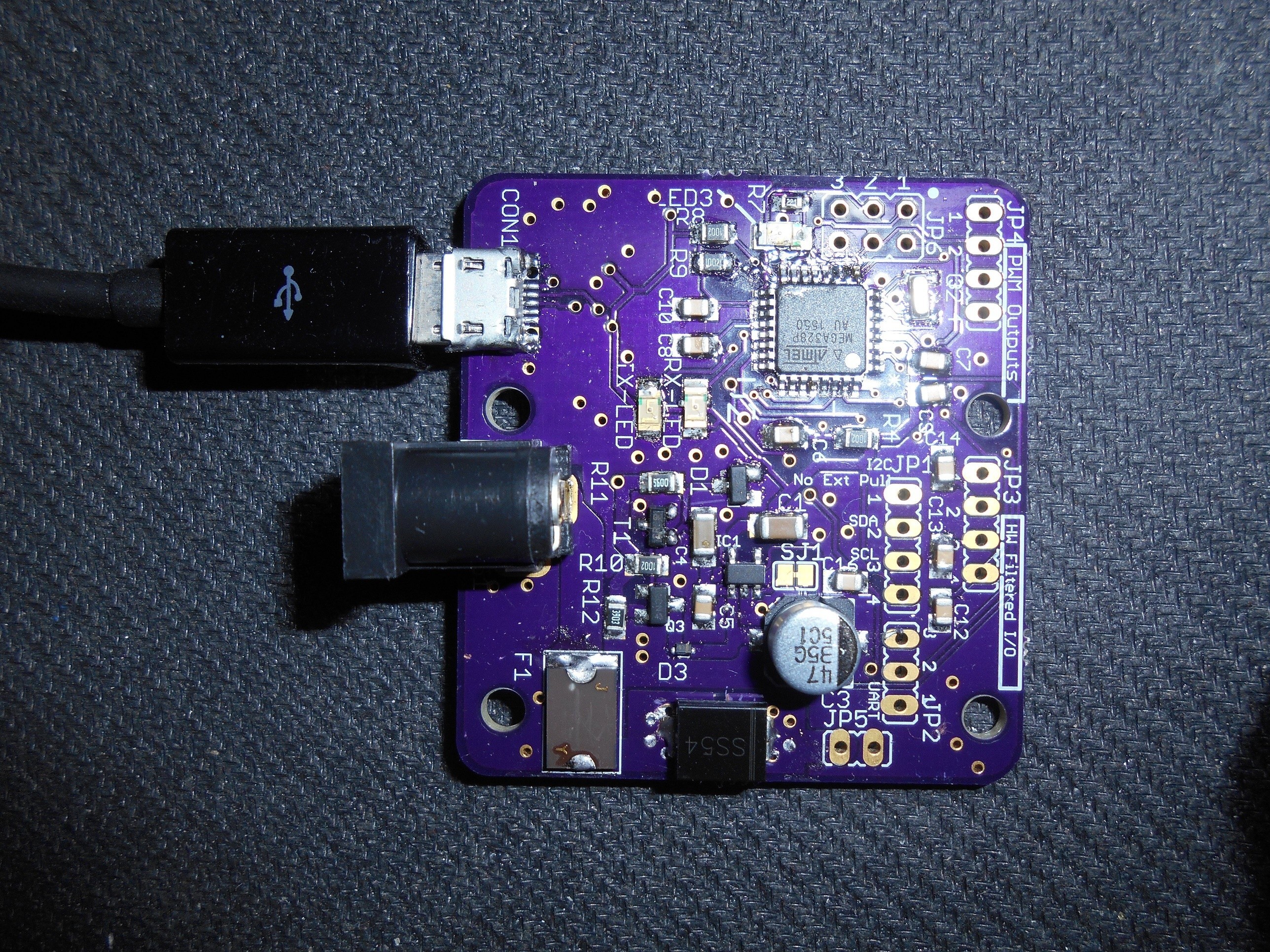
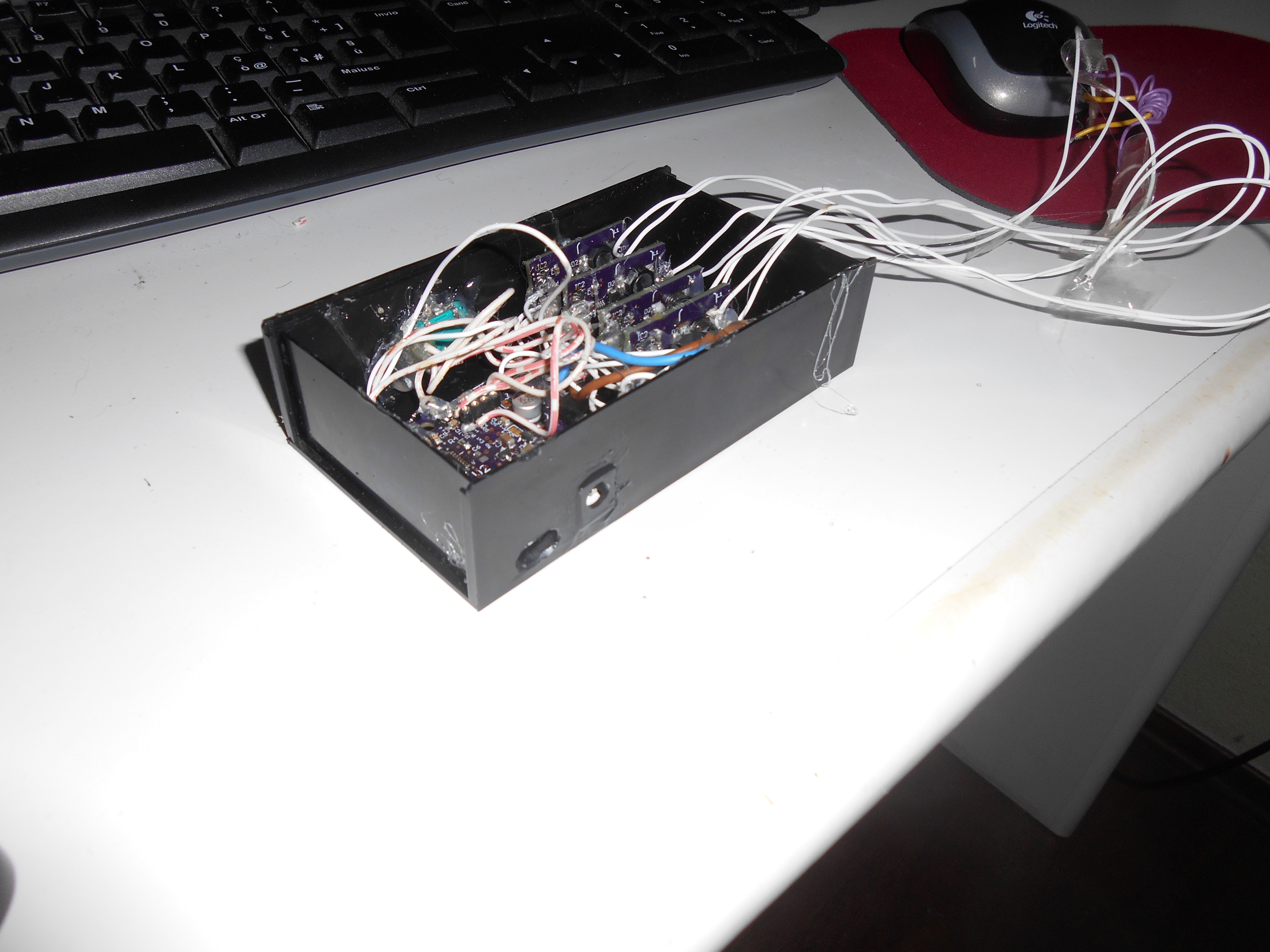 A detail of the controller board once in the box. On one side there is the power jack and USB connector for the remote/automatic control, on the other the encoder for the manual control.
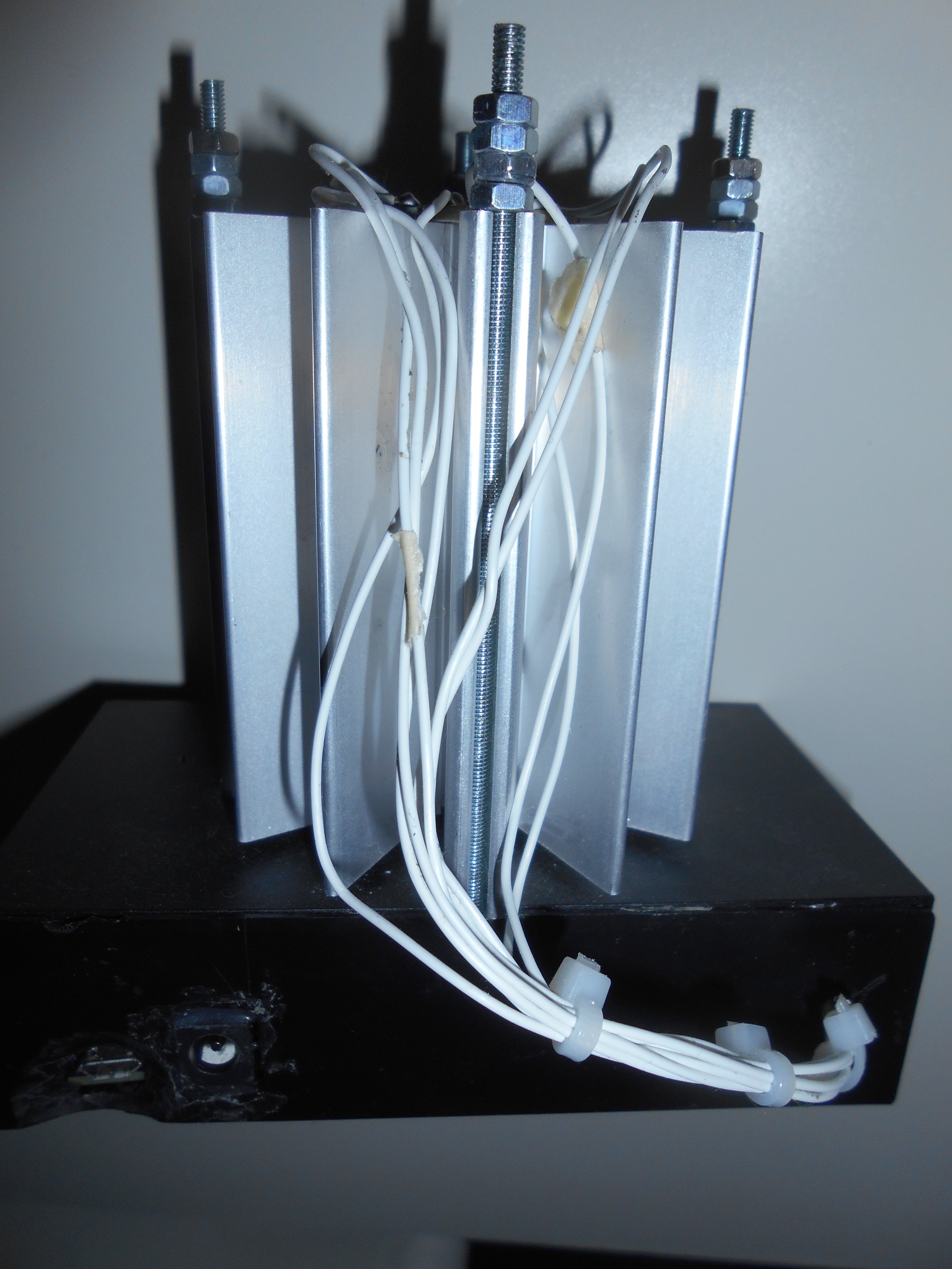
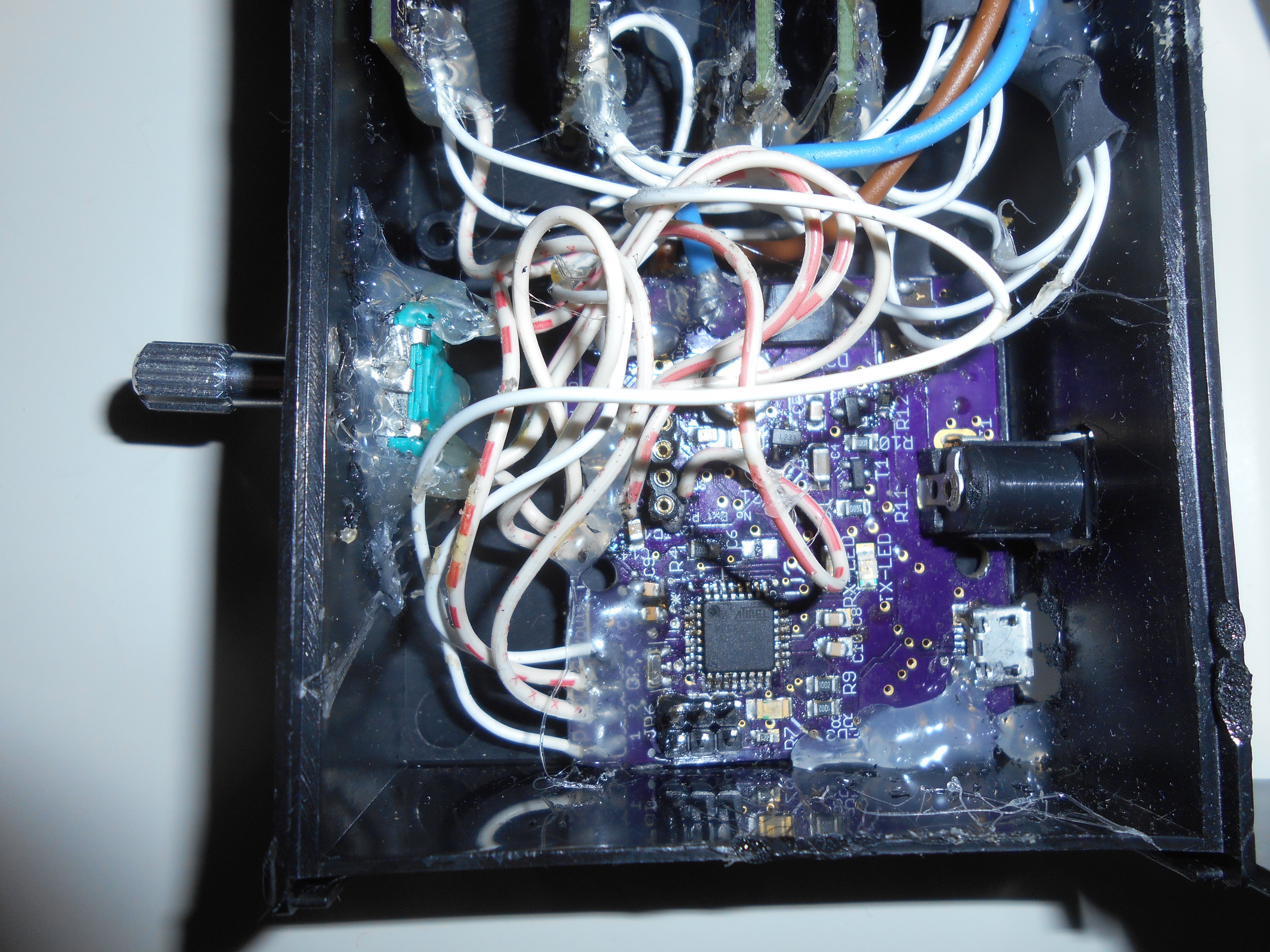 A detail of the power boards, just one hole made to let the wires pass through.
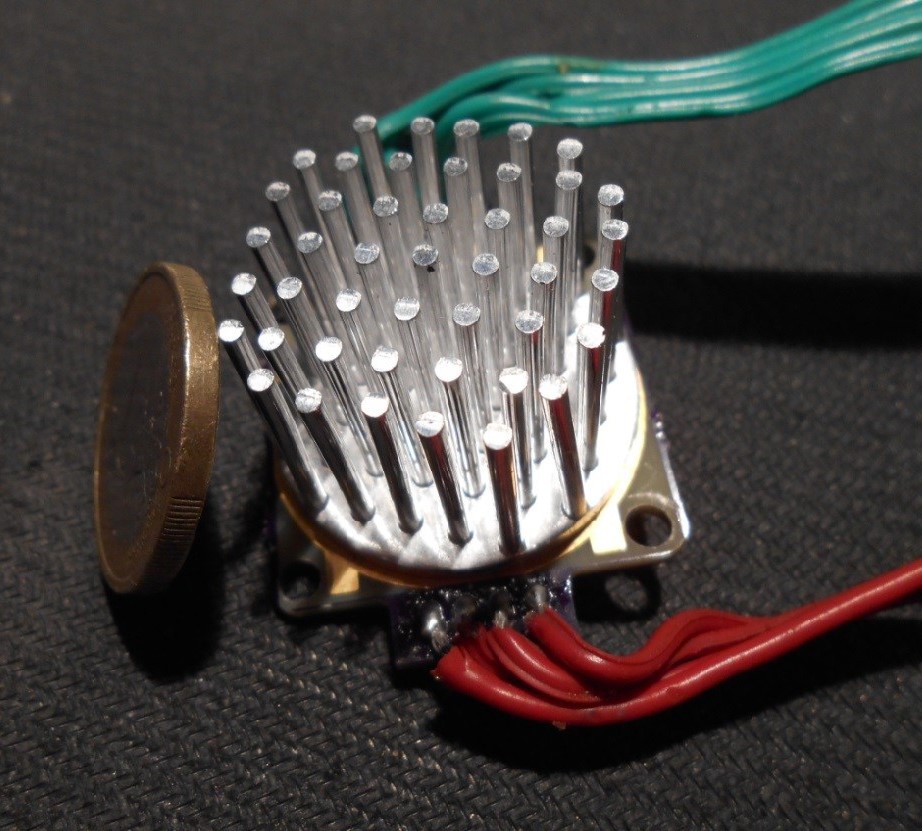
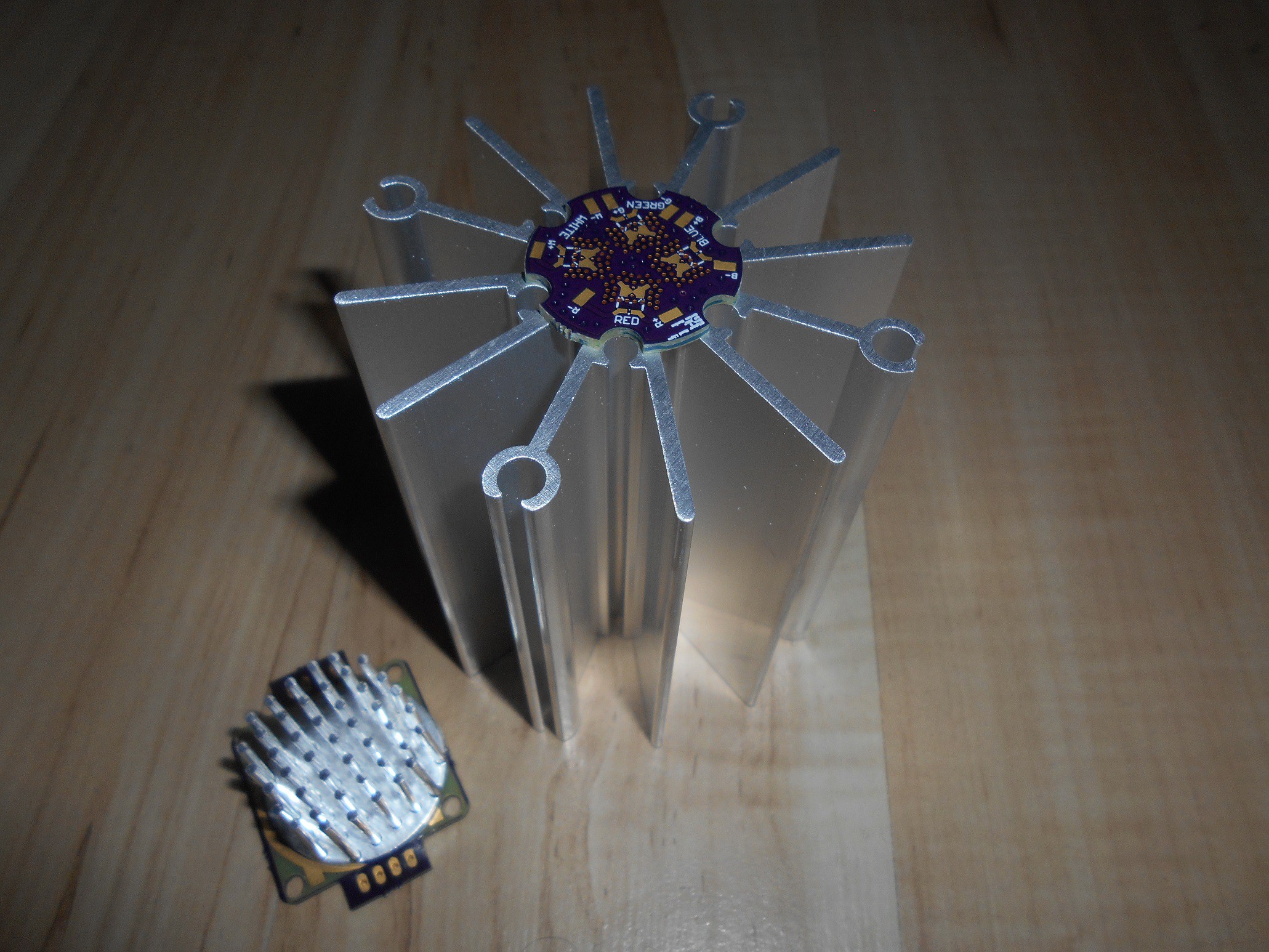
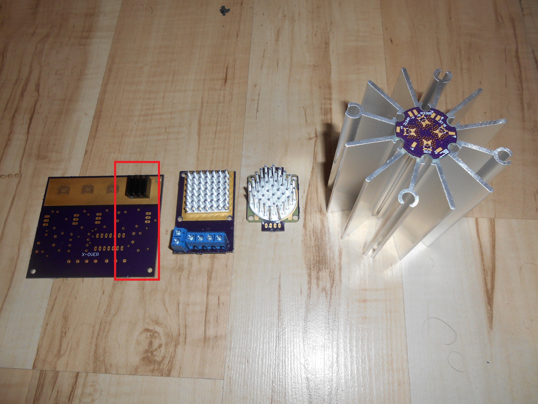
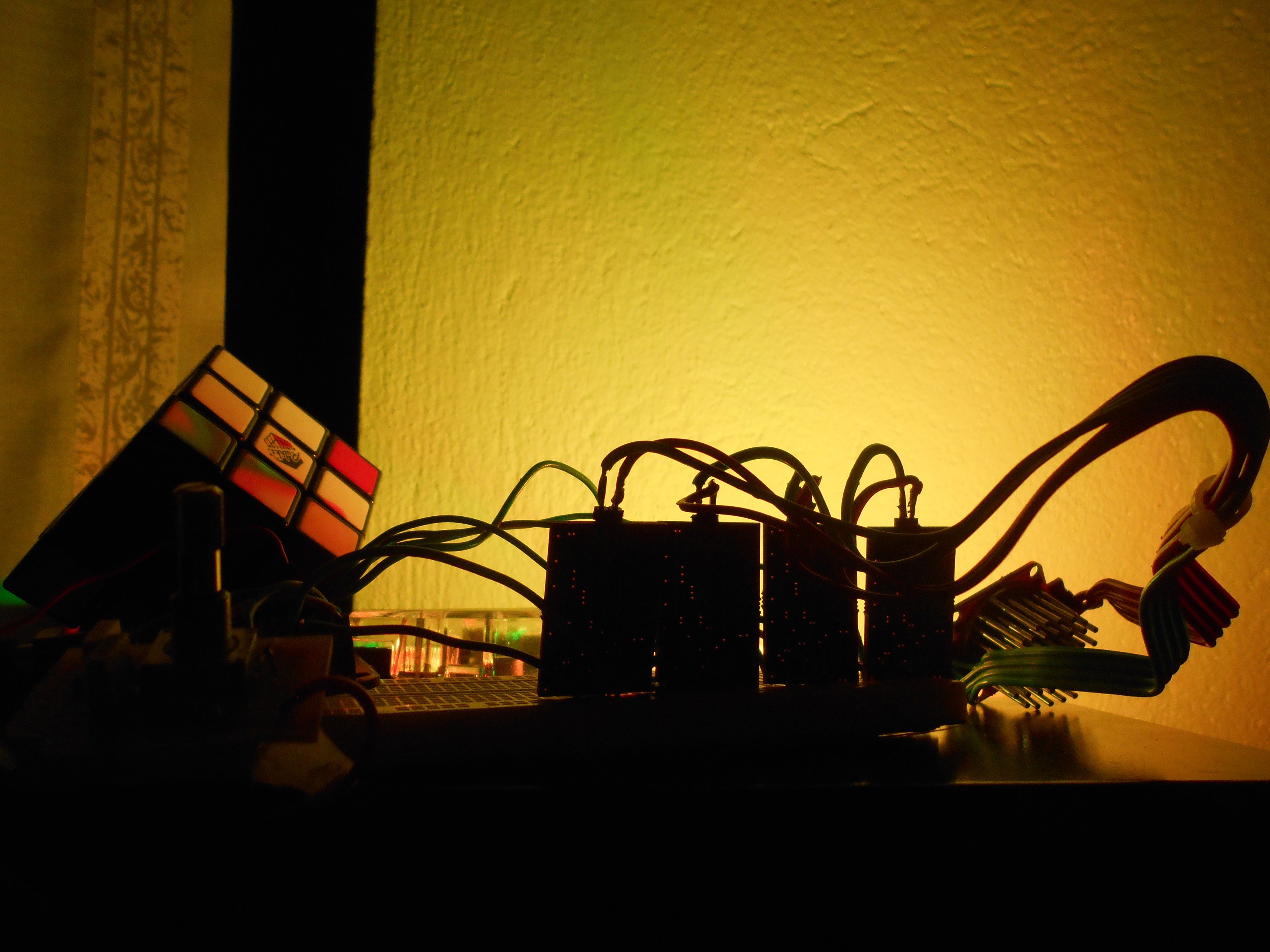
 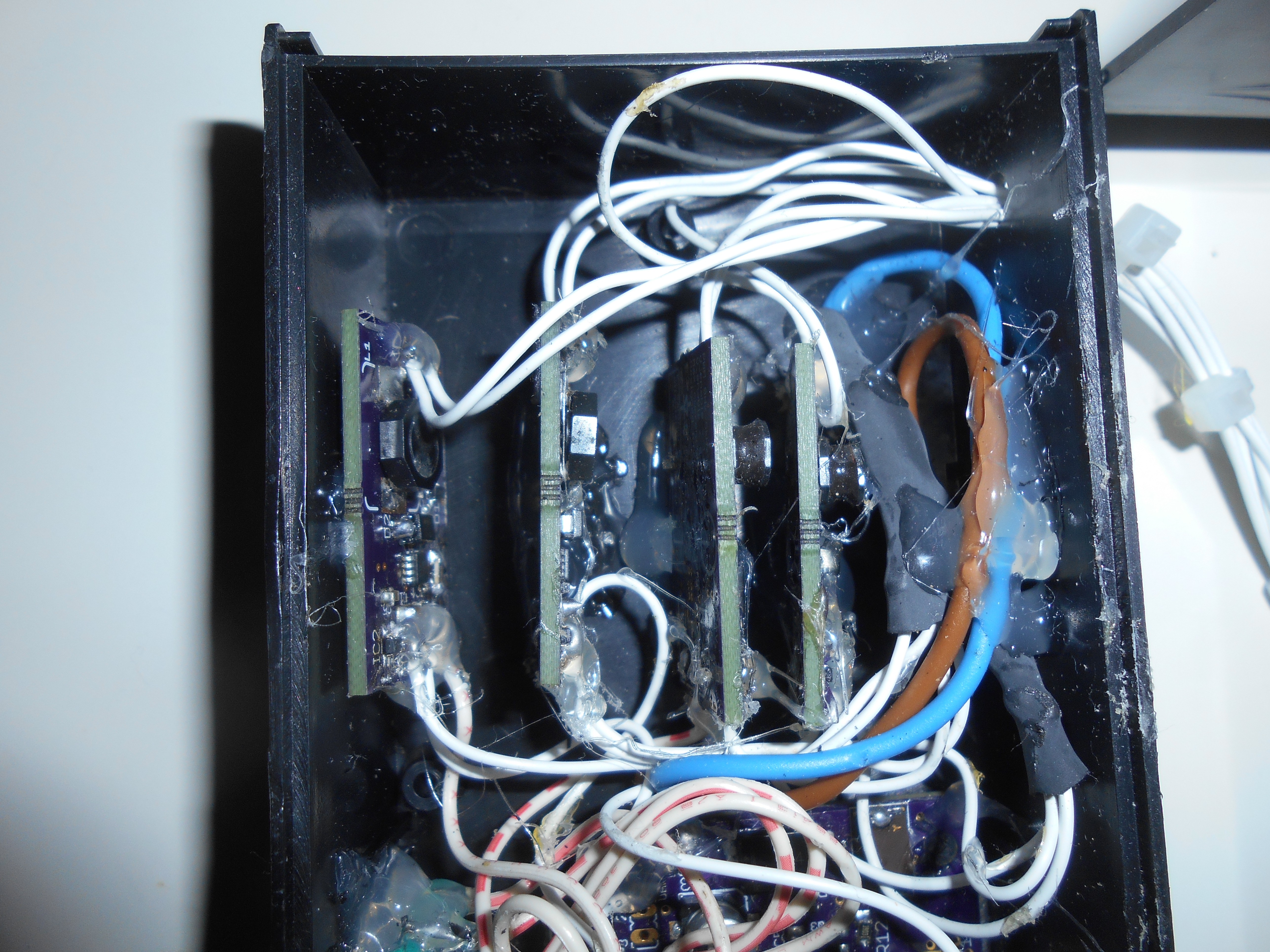 The wires are then connected to the LED engine, which is connected to the heatsink by means of thermal tape. The heatsink provides space to use some threaded rods which I used as shown.
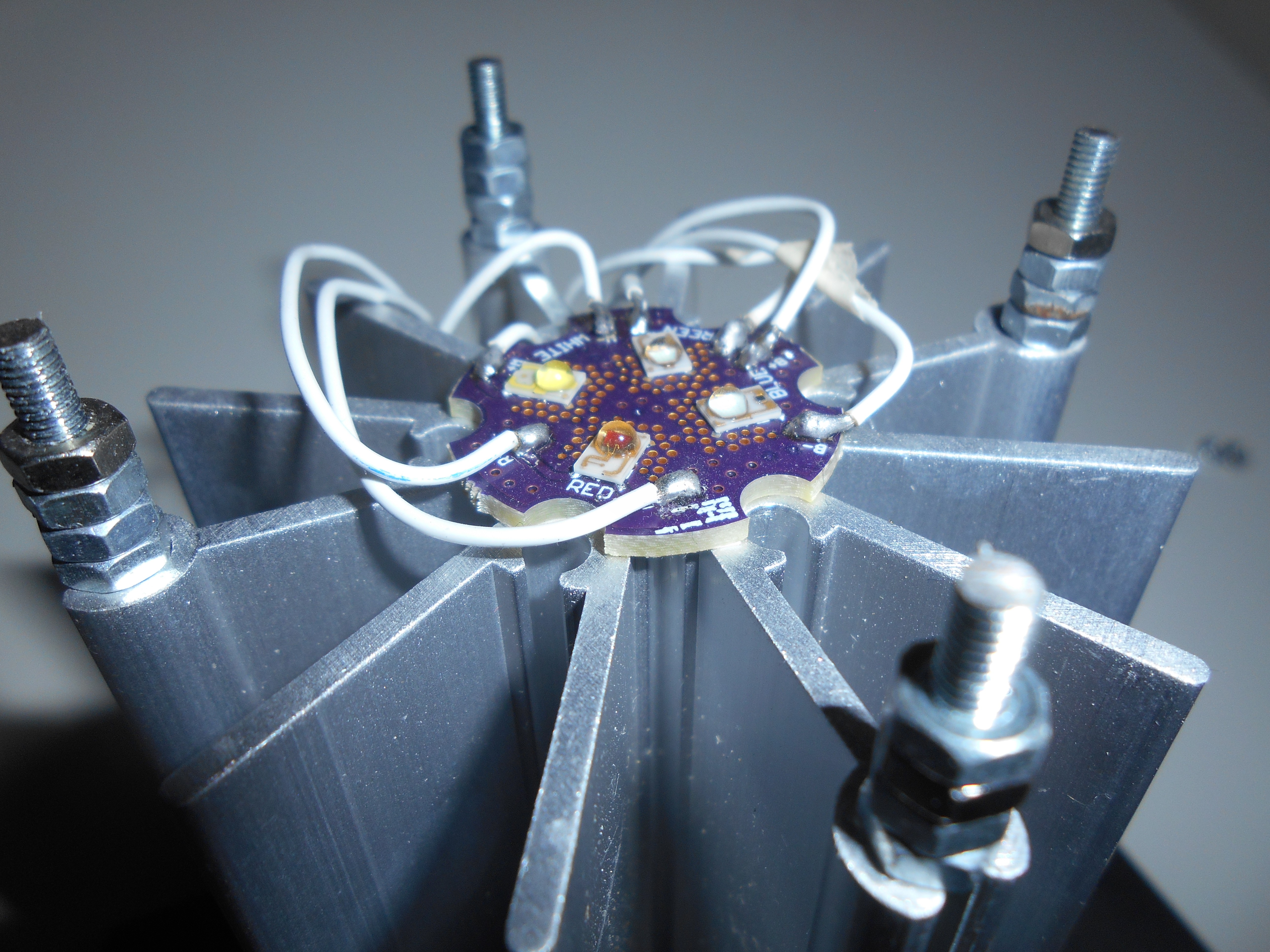
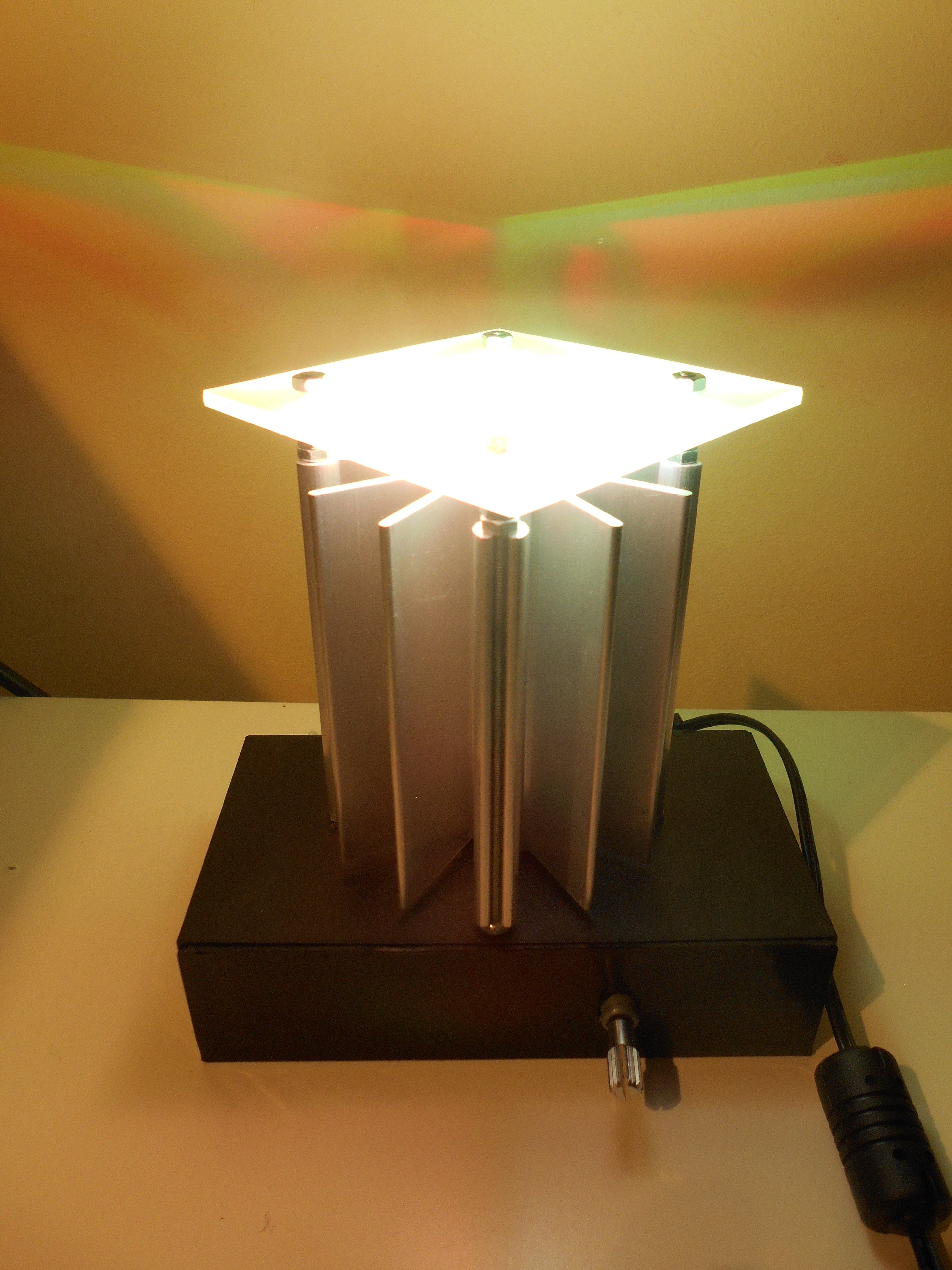
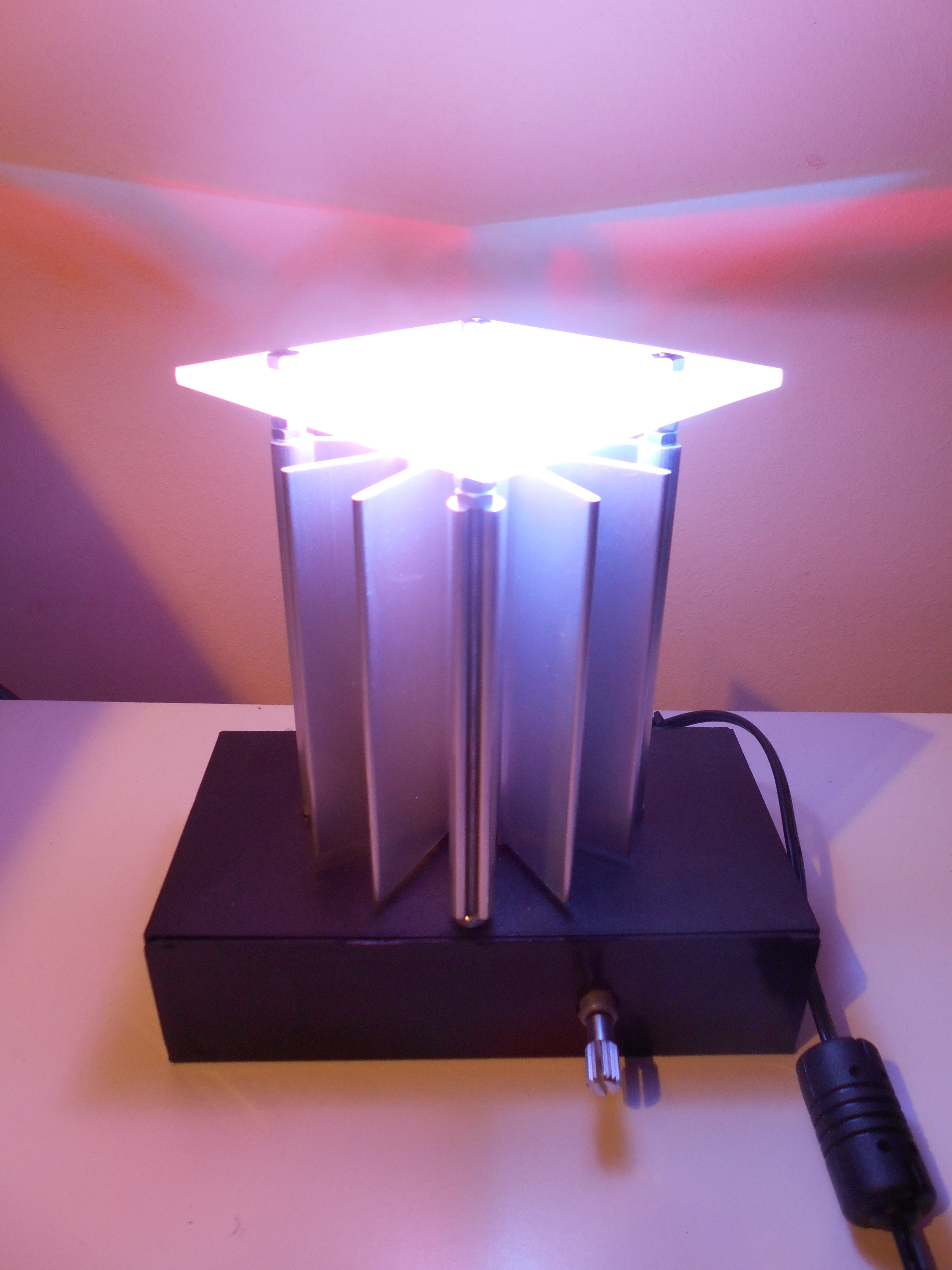
 And the final result look like this:
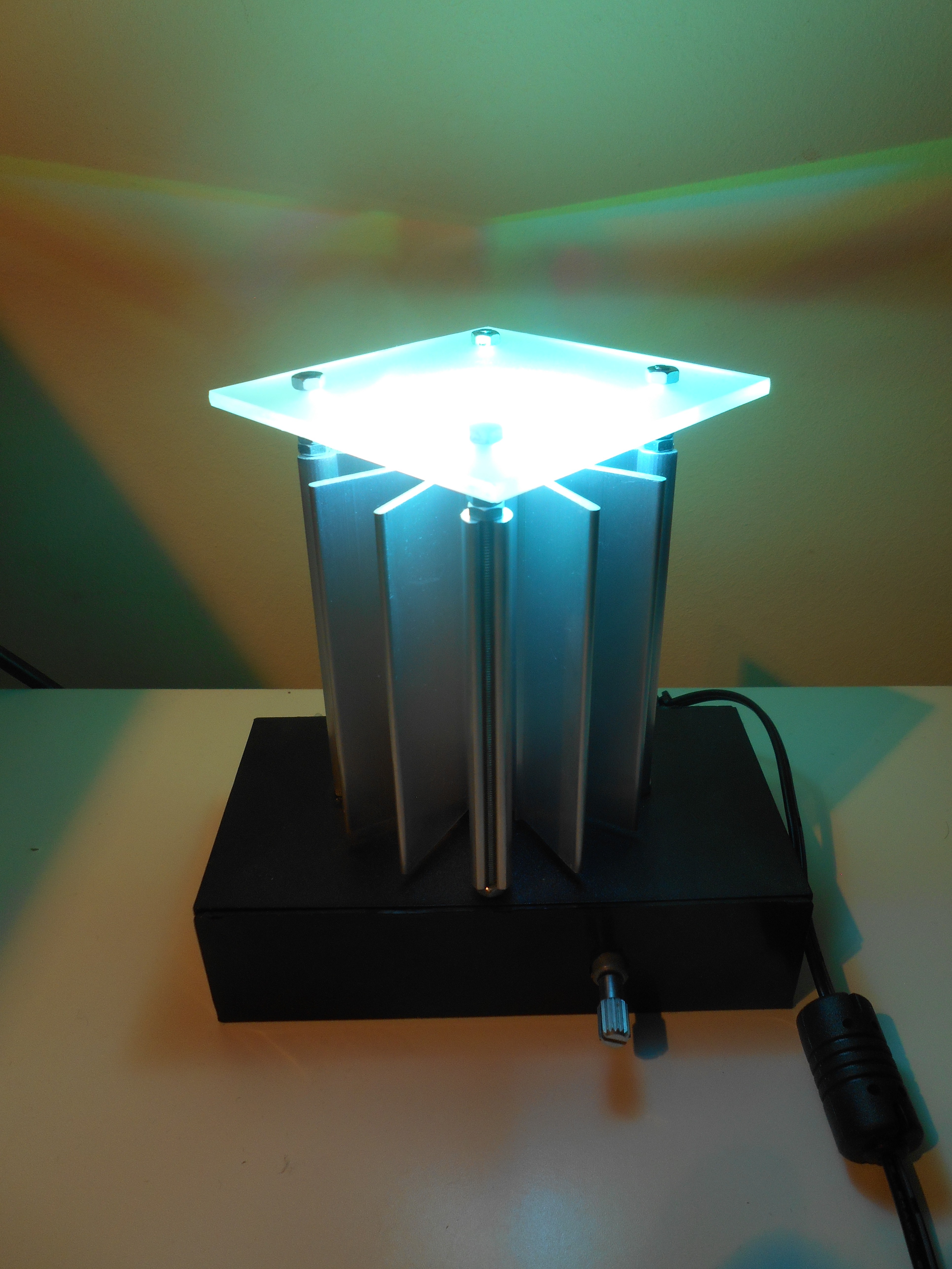


 Adam Demuri
 icstation
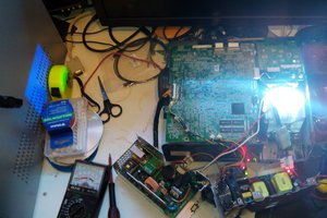
 ric866
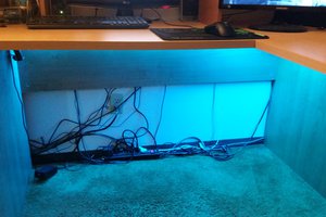
 Scott Clandinin
Great project!