 Bud Bennett
My Project Rationale:
A 600 foot deep well provides water to my house. The well only produces 8 gallons/hour. Therefore I also have a 1700 gallon cistern to store the water before it is pumped into the house for use. There is a float valve that turns on the deep well pump when the cistern level drops to a certain level below full and turns off the deep well pump when it is full again. The pump is a 1hp 250VAC induction motor.
My project is to monitor the status of the cistern to make sure that it doesn't run dry. I thought that the easiest way to do this would be to monitor how often, and for how long, the deep well pump is running. I assumed that simply detecting a voltage applied to the motor would be a good indicator of this, so I proceeded to design a circuit for detecting a 250VAC signal and presenting to the Raspberry Pi as a GPIO logic level.
Design Requirements:
1. Safety: 2500-3500V galvanic isolation between motor circuit and RPi circuit.
2. Cool Operation: low power dissipation…
3. Simple, two-wire interface: GND and GPIO signal to the RPi. No power supply signal required.
4. Small size - it has to fit inside the well "pump-saver" box that is mounted on the garage wall, and it won't be the only circuit in the box.
Effect of Component Failures:
These circuits should be evaluated for failure effects to see what bad things happen when components fail. I did some investigating of how and why electronic components fail. Here's some of what I found:
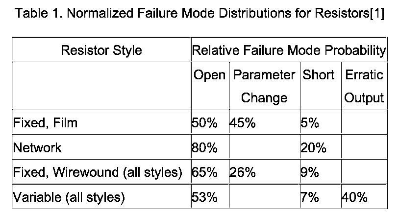
[1] Failure mode data was taken from a combination of resistor manufacturer's recommendations, MIL-HDBK-978, "NASA Parts Application Handbook," 1991; MIL-HDBK-338, "Electronic Reliability Design Handbook," 1994; "Reliability Toolkit: Commercial Practices Edition," Reliability Analysis Center (RAC), 1998; and "Failure Mode, Effects, and Criticality Analysis (FMECA)," RAC, 1993.
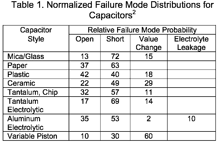
[2]Failure mode data was taken from a combination of MIL-HDBK-978, “NASA Parts Application Handbook”, 1991; MIL-HDBK-338, “Electronic Reliability Design Handbook”, 1994; “Reliability Toolkit: Commercial Practices Edition”, Reliability Analysis Center (RAC), 1998; and “Failure Mode, Effects, and Criticality Analysis (FMECA)”, RAC, 1993.
Capacitors normally fail with a short circuit. Film resistors most likely fail with an open circuit, but can fail just as often with a parameter change, and only fail shorted 5% of the time.
Component Ratings:
Only use components rated to withstand the electrical environment to which they are subjected. Design for Reliability guidelines suggest that resistors be derated to 60% of maximum operating limits for voltage and power dissipation. This was an eye-opener for me. This is serious stuff and a failure could cause a fire or other serious issue that places the occupants of the house in danger. It gives credence to the people who say "Don't play with the mains."
This is the circuit that I initially implemented:
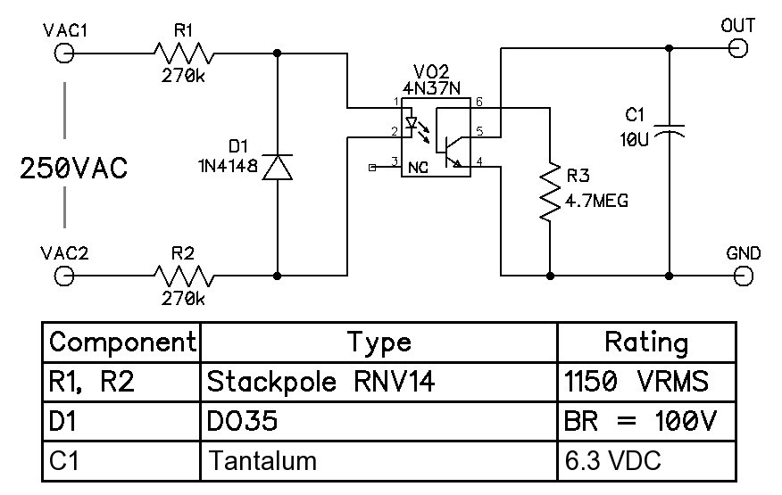
Vishay has a handy data sheet that covers multiple general purpose transistor output optos - you can find it here. The data sheet specifies the transfer characteristics of the coupler with a forward current, IF, through the input LED @ 10mA. This is a problem. If the input resistors must generate 10mA with 125VAC across them then they will need to be rated for 2 Watts!
In order to make R1 and R2 larger the opto-isolator has to be operated at lower currents. I selected the 4N37 because its minimum Current Transfer Ratio (CTR) is 100%. There is not a load resistor in the circuit - it is provided by the RPi. The GPIO pull-up resistor is 50K minimum. Therefore the 4N37 must sink 3.3V/50k = 66uA max. And we'll increase that by 50% to make sure that the 4N37's output NPN is fully saturated (producing a low output voltage). So we now know that the output current is 100uA. The CTR of the 4N37 is estimated, using Figures 3 and 5 and iterating a bit, to find IF produces a CTR of about 0.15. (Operating on this part of the CTR curve is a bit scary due to the steep slope at IF = 1mA.) Therefore the input resistor must produce 100uA/0.15 = 667uA peak:
2R = 250VAC * sqrt(2)/667uA = 530 kOhm => 2 * 270kOhm
The power dissipation in each input resistor is:
P = V^2/R = 125VAC^2/270k = 58mW, which is about 25% of the rating for a 1/4W resistor.
How hot will the resistors get? Find a 1/4W wire wound resistor data sheet (try Digikey.com) and find that the dissipation factor is about 320-350C/W. Therefore these two resistors will have a steady state temperature of:
T = 0.058W * 320C/W + 25C = 44C (50C is too hot to touch for very long, so this is probably OK)
These Stackpole RNV14 resistors have a working voltage of 1150VRMS, 1600VDC, and can handle surges to 7kV. They are available from www.digikey.com.
Effects of component failure:
If either R1 or R2 short circuits (a 5% failure mechanism) then the power dissipation of the other resistor will quadruple to 0.212W, which is still below its rating. The circuit will continue to operate, but the temperature of the non-shorted resistor will increase to around 90C. This might cause the circuit to fail due to high operational temperatures, but at least it won't be catastrophic. So a fuse is not required. It might be a good idea to vent the enclosure though.
R1 and R2 have an operating voltage rating of 1150VRMS so they will probably survive surges and transients from the main power lines without issues and don't require any additional protection.
The opto LED aging factor is reduced by a factor of 15 compared to running the LED current at 10mA.
Breadboard Results:
It works without issue. I just cut a piece of perfboard and mounted the components, giving wide spacing to the input terminals and R1, R2. Here's a photo of the board mounted in a small plastic case that was used to store SMD components:

This particular piece of perfboard does not have any copper traces along the underside of the left edge of the board which would defeat the spacing effect. Sharp eyes will notice that the date code on the 4N37 is 1982...
Still not satisfied:
Though I like the simplicity of this circuit am concerned about its stability over time. I did an internet search for other opto-isolator circuits and found this article written by Peter Demchenko: http://m.eet.com/media/1133289/6512151.pdf which claimed to overcome excessive power consumption, uncertain switching and LED aging. I was able to simplify his approach down to this circuit:

Theory of operation:
During the AC cycle when VAC1>VAC2, C2 is charged to about 30V by R1,R2 and D2, and Q1 is off. When VAC1-VAC2 drops below 30V Q1 turns on, saturates, and forces about 5mA through the opto LED for about 600-800us while discharging C2. C2 remains discharged until VAC1 - VAC2 is positive again. So basically C2 stores energy and then releases it in a relatively short burst.
Now the LED current is back up in the sweet spot of the CTR curves for all of the generic opto-isolators. Power dissipation is about the same, perhaps a bit less. The added components are cheap and can be surface mount so don't require much additional space.
There is one concern - the on-time of the opto NPN is relatively short so it must be able to drive the output capacitor to a low voltage in that time period. Therefore I'm still using the optos with higher CTR specs (4N35/4N36/4N37).
Effects of component failure:
If R1 or R2 short circuits then C2 will be charged to about 60V, hence the 100V rating. Q1 has a LVCBO = 80 V so there is no problem. D2 will withstand 100V reverse so it will not be affected.
The LED aging is unchanged from the earlier circuit since the average LED current has not changed.
Breadboard Results:
LTSPICE was used to verify circuit operation. Heres what the PCB looks like:
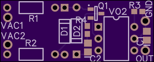
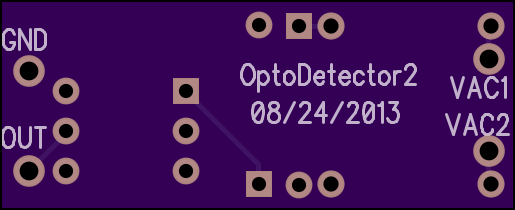
The board is pretty small: 32.69x13.33 mm. Note that there are large spacings at the left side of the board to afford high electrical isolation. The inputs are 4mm apart so I figure there is around 4kV of isolation. There are no traces running under the opto-isolator so it should yield 6kV. OSH Park charged me $3.35 for three of these PCBs, shipping included.
I received my PCBs and rated components and built the board. It works well - measured Vout ~200mV when 250VAC is present. End of story.
Sensing Current:
The only problem is that it only reports half of the information that I need to determine the status of the well and cistern. It turns out that the guy who installed the pump and cistern wired the float switch to the output of the pumpsaver module. If the float switch is open then the pumpsaver output is constant 250VAC. If the float switch is closed, the pump runs until the float switch opens or the pump runs dry - in which case the pump saver output switches off for a set interval and then switches on the 250VAC. This cycle repeats until the cistern is full and the float switch is open.
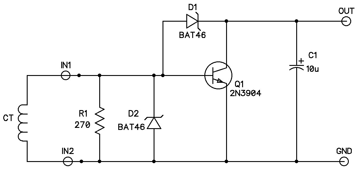
So to find out when the pump is running it is required to sense the 8-9 Amps of current from the output of the pumpsaver. This is most easily done (at least for me) by using a current transformer (CT) and the following circuit.
The CT just slips over one of the pumpsaver output leads. No muss no fuss. You will have to disconnect the lead and reconnect it.
Don't even think about winding your own CT. CR Magnetics makes a nifty 10A rated CT with 1000 turns - so 9A to the pump equals 9mA out of the CT. The best deal that I found for this part was from Amazon.com for $8 USD and free shipping if you're an Amazon Prime member. The max continuous primary current is four times the rated current, so this component has some range to it. Insulation voltage is 3500VAC - similar to an opto-isolator.
A NOTE OF CAUTION: A CT WILL PRODUCE HIGH OPEN CIRCUIT VOLTAGES DUE TO THE HIGH TURNS RATIO. ALWAYS TERMINATE THE CT WITH AN APPROPRIATE LOAD BEFORE INTRODUCING IT INTO THE CIRCUIT AND APPLICATION OF POWER.
This is so much easier than messing with high voltage. The circuit above is all low voltage and component ratings don't mater much (except that you want to use a low current Schottky diode because the reverse leakage current of a high current diode - e.g. 1N5818 - will degrade your output voltage with no current applied to the point of making it look like a logic low.) You don't really need the resistor - I just put it in to provide a 2A threshold for a bit of noise rejection.
With 9Amps AC applied the output to the GPIO is roughly 0.4VDC. The CT voltage is clamped to about 1Vpeak, which is good since the input impedance is reflected back to the pump motor by the inverse square of the turns ratio (1000:1). The transistor Q1 looks like a 4 Ohm resistance to the CT therefore the equivalent resistance in series with the pump load is about 4 milli-Ohm, which is negligible.
The Code:
I generally suck at coding. But here is what I'm currently using to monitor the well and cistern. Emails are sent at boot, if the pump has run too long, if the deep well pump hasn't run after 200 gallons have been pumped into the house (the watchdog), and daily at 7:00am. If things are running normally I will get a status email once/day. With the cistern full, the pump runs at 18-24 hour intervals so sometimes the emails have nothing to report.
#!/usr/bin/env python3
# this file is located in ~/programs
# Deep well pump voltage sensor is on GPIO25
# Deep well pump current sensor is on GPIO24
# Cistern/house pump voltage is on GPIO22
"""
Deep Well/Cistern Conditions:
Voltage Current
   Y      Y     Pump is running. Capture run time and run interval. Fault if run time > TBD.
   Y      N     Pump is not running, but cistern is full. Fault if pump off interval > TBD.
   N      Y     Condition can't happen if circuits are working properly - send email with fault info.
   N      N     Well has run dry. Cistern is not full. Pump will cycle at PumpSaver interval. Fault if cycle time > TBD.
"""
import RPi.GPIO as GPIO
import time
from datetime import datetime, timedelta
import smtplib, _thread  # for email thread
from email.mime.text import MIMEText  # for email
from bottlepy_user_auth import User
# define global variables
bootTime = lastRun = datetime.now()
runNumber = runtimeTotal = house_runtimeTotal = maxPumpInterval = maxRuntime = 0
minRuntime = None
minPumpInterval = None
email_flag = True
run_flag = False
run_houseflag = False
dog_total = 0
gallonsTotal = 0
dryWell = 0
wellStatus = ""
class emailer:
    def __init__(self, user, userPW, emailServer='smtp.gmail.com'):
        ''' initiallize parameters '''
        self.__user = user
        self.__userPW = userPW
        self.__emailServer = emailServer
        self.system_name = 'Well Monitor: '
        # Get boot time
        now = datetime.now()
        self.boot_time = ' %s' % now.strftime('%Y %b %d  %H:%M:%S')
        print('Send Boot Email')
        self.send_status_email('Starting Up Bennett Well Monitor',
                               'Well monitor is booting up - may have been a power outage.')
    def sendemail(self, subject, message):
        # use thread to send email
        _thread.start_new_thread(self.send_through_secure_smtp, (subject, message))
    def send_through_secure_smtp(self, subject, message):
        msg = MIMEText(message)
        msg['Subject'] = subject
        msg['From'] = self.__user
        msg.add_header('To', self.__user)
        msg.add_header('Cc', "")
        try:
            server = smtplib.SMTP(self.__emailServer, 587)
            server.ehlo()
            server.starttls()
            server.ehlo
            server.login(self.__user, self.__userPW)
            server.sendmail(self.__user, msg.get_all('To') + msg.get_all('Cc'), msg.as_string())
            server.quit()
            print("Successfully sent email.")
        except smtplib.SMTPException:
            print("Error: Unable to send email.")
    def send_status_email(self, message, status_text):
        now = datetime.now()
        time_now = ' %s' % now.strftime('%Y %b %d  %H:%M:%S')
        self.sendemail(self.system_name + message,
                       '\n Message: ' + message + '\n' + status_text + '\n Boot time:' +
                       self.boot_time + '\n Time Now:' + time_now)
class watchdog():
    ''' The watchdog is reset every time the deep pump runs.
    If the deep pump hasn't run after the house pump has run for 750 seconds,
    then it sends an email. '''
    def __init__(self, housePumpMax=750):
        self.housePumpMax = housePumpMax
        print("Initializing the Watchdog")
    def checkDog(self, dog_total):
        if (dog_total > self.housePumpMax):
            mail.send_status_email("Pump Watchdog", "Deep Pump has not run since {0} gallons have been pumped \
                                   into the house.".format(dog_total/60*12))
            print("WARNING: More than {0} gallons have been pumped into house since the deep pump has \
                  run.".format(self.housePumpMax/60*12))
            return 1
        else:
            return 0
def calculateGallons(runTime, housePumpDuration, dry_well):
    """Pump:STA-RITE 1hp/5GPM. The pump runs at a higher rate when its head is lower: i.e. when the well is full.
    It is assumed that the float valve will let in a relatively constant amount of water.
    Therefore, if the pump runs longer, the well is not full (not at it's static level). So
    the gallons are constant until the well runs dry and then we assume that it can pump
    about 3 gallons/minute in that condition.
    If the house pump runs during the deep well pump operation then the runtimes are modified to take into
    account the 12GPM of the house pump.
    """
    global wellStatus
    if(dry_well):
        gallons = runTime.seconds * 3/60  # assume 3 gallons/minute for head = 600 feet
        wellStatus = "Well is Dry and Cistern level is unknown"
    else:
        if (runTime.seconds < 850.0 + housePumpDuration * 12/8):
            gallons = runTime.seconds * 8/60  # assume 8 gallons/minute at head = 110 feet
            wellStatus = "Cistern is full and Well is full"
        elif (850.0 + housePumpDuration * 12/8 >= runTime.seconds < 915.0 + housePumpDuration * 12/7.5):
            gallons = runTime.seconds * 7.5/60  # assume 7.5 gallons/minute at head = 210 feet
            wellStatus = "Cistern is full and Well is less than 3/4 full"
        elif (915.0 + housePumpDuration * 12/7.5 >= runTime.seconds < 1280.0 + housePumpDuration*12/7.0):
            gallons = runTime.seconds * 7.0/60  # assume 7 gallons/minute at head = 350 feet
            wellStatus = "Cistern is full and well is less than 1/2 full"
        else:
            gallons = runTime.seconds * 5.0/60  # assume 5 gallons/minute at head = 500 feet
            wellStatus = "Cistern is full and well is less than 1/4 full"
    return gallons
def timeDelta2Str(seconds):
    """ takes seconds and formats it into a string of "hrs:minutes:seconds" """
    hrs, remainder = divmod(seconds, 3600)
    minutes, seconds = divmod(remainder, 60)
    timestr = "{0}:{1}:{2}".format(hrs, minutes, seconds)
    return timestr
def deepPumpRunning(channel):
    global runNumber, runtimeTotal, email_flag, lastRun, minPumpInterval, maxPumpInterval
    global minRuntime, maxRuntime, run_flag, run_houseflag, gallonsTotal, dryWell, wellStatus, dog_total
    # de-glitch
    if(run_flag):
        # exit if the run_flag is already set - to prevent more than one thread running during a single pump run
        return
    # set the run_flag to True while the pump runs
    run_flag = True
    housePumpDuration = 0
    pumpStart = datetime.now()
    while (not GPIO.input(24)):
        time.sleep(1)
        runtime = datetime.now() - pumpStart
        if(runtime.seconds == 5):
            print("The pump is running.")
        # send email if pump runs too long
        if (runtime.seconds == 60*60):
            mail.send_status_email("Pump Running Too Long", "Pump has been running for over 1 hour.")
        # keep track of house pump activity during deep well pump operation
        if (run_houseflag):
            housePumpDuration += 1
    pumpStop = datetime.now()
    runtime = pumpStop - pumpStart
    pumpInterval = pumpStart - lastRun
    pumpInterval_seconds = pumpInterval.days*24*3600 + pumpInterval.seconds
    if (runtime.seconds > 5):
        dog_total = 0  # reset the total house pump runtime since last deep well pump operation
        runNumber += 1
        # collect pump data
        if (runtime.seconds > maxRuntime):
            maxRuntime = runtime.seconds
        if (runNumber == 1):
            minRuntime = runtime.seconds
        elif (runtime.seconds < minRuntime):
            minRuntime = runtime.seconds
        if(pumpInterval_seconds > maxPumpInterval or runNumber == 1):
            maxPumpInterval = pumpInterval_seconds
        if (runNumber == 1):
            minPumpInterval = pumpInterval_seconds
        elif (pumpInterval_seconds < minPumpInterval):
            minPumpInterval = pumpInterval_seconds
        # real time data:
        print("Well pump started at ", pumpStart)
        print("The pump ran for {0:.1f} minutes".format(runtime.seconds/60))
        print("The house pump ran for {0} seconds during deep well pump operation.".format(housePumpDuration))
        print("Pump Data:")
        print("    Number of pump runs: ", runNumber)
        print("    Max runtime: {0:.1f} minutes".format(maxRuntime/60))
        print("    Min runtime: {0:.1f} minutes".format(minRuntime/60))
        print("    Max pump interval (hrs:min:sec): {0} ".format(timeDelta2Str(maxPumpInterval)))
        print("    Min pump interval (hrs:min:sec): {0}".format(timeDelta2Str(minPumpInterval)))
        lastRun = pumpStart
        # wait 10 seconds then check pump voltage to see if well ran dry
        # well ran dry if pump saver switched off voltage to pump (GPIO 25 is High) after run
        time.sleep(10)
        dryWell = GPIO.input(25)
        gallonsTotal += calculateGallons(runtime, housePumpDuration, dryWell)
        print(" ")
        runtimeTotal += runtime.seconds
        print("Pump total runtime since last email = {0:.1f} minutes".format(runtimeTotal/60))
        print("Total gallons produced since last email = {0:.1f}".format(gallonsTotal))
        print("Well Status: "+wellStatus)
        print("")
    # turn off the pump_flag
    run_flag = False
def housePumpRunning(channel):
    """ The pump that provides water to the house from the cisern
        is a STA-Rite rated at 1/2HP 10 GPM. The pump operates without
        any head because the house is below the cistern. Actual GPM (measured) is 12.
    """
    global run_houseflag, house_runtimeTotal, dog_total, run_flag, dog
    if (run_houseflag):
        # the pump is already running - this is a glitch in the sensor
        return 1
    # set the run_flag to True while the pump runs
    run_houseflag = True
    housepumpStart = datetime.now()
    while (not GPIO.input(22)):
        time.sleep(1)
    houseRuntime = datetime.now() - housepumpStart
    if (houseRuntime.seconds > 5):
        house_runtimeTotal += houseRuntime.seconds
        dog_total += houseRuntime.seconds
        print("House pump started at ", housepumpStart)
        print("The house pump ran for {0} seconds".format(houseRuntime.seconds))
        print("Total pump runtime since last email = {0:.1f} minutes".format(house_runtimeTotal/60))
        print("Total house gallons since last email = {0:.1f}".format(house_runtimeTotal/60*12))  # 12 GPM
        print("Total house gallons since last deep pump run = {0:.1f}".format(dog_total/60*12))
        print(" ")
    run_houseflag = False
    if (run_flag):
        dog_total = 0
        print("Watchdog reset because deep pump is running.")
        print(" ")
    if (dog.checkDog(dog_total)):
        dog_total = 0
        print("Watchdog reset after being triggered.")
        print(" ")
    return 1
GPIO.setmode(GPIO.BCM)
GPIO.setup(22, GPIO.IN, pull_up_down=GPIO.PUD_UP)
GPIO.setup(24, GPIO.IN, pull_up_down=GPIO.PUD_UP)
GPIO.setup(25, GPIO.IN, pull_up_down=GPIO.PUD_UP)
GPIO.add_event_detect(24, GPIO.FALLING, callback=deepPumpRunning, bouncetime=10)
GPIO.add_event_detect(22, GPIO.FALLING, callback=housePumpRunning, bouncetime=10)
# email username and password are encrypted and stored in a SQlite3 database
user = User(debug=False)
print("\nDecrypting...this could take a while...\n")
email = user.get_email("Master")
mail = emailer(user=email[0], userPW=email[1], emailServer='smtp.gmail.com')
# set the watchdog to bark when house pump gallons exceed 200 before the deep pump runs.
dog = watchdog(housePumpMax=200/12*60)  # 200 gallons/12GPM*60seconds
try:
    print("Waiting for falling edge on GPIO24 or GPIO22")
    print("email flag is", email_flag)
    while True:
        timeNow = datetime.now()
        if (timeNow.hour < 7):
            email_flag = False
        # send status email after 7:00 am, but only send one
        if (timeNow.hour > 6 and not email_flag):
            # if pump is running - wait
            if(run_flag):
                time.sleep(60)
                continue
            # send status email
            try:
                lastRun_time = ' %s' % lastRun.strftime('%Y %b %d  %H:%M:%S')
                # debug: print("Last Run Time:", lastRun_time)
                if (runNumber == 0):
                    statusText = "There is no pump data since it hasn't run since "
                    if (bootTime != lastRun):
                        statusText = statusText + "the last email.\nThe last time that the pump ran was {0}\n".format(lastRun_time)
                    else:
                        statusText = statusText+"boot.\n"
                else:
                    statusText = (wellStatus+"\nNumber of pump runs: {0}\nGallons produced since yesterday = "
                                 "{1:.1f}\nMaximum Pump Interval (hrs:min:sec) = {2}\n"
                                 "Minimum Pump Interval (hrs:min:sec) = {3}\n"
                                 "Maximum Pump Run Time = {4:.1f} minutes\nMinimum Pump Run Time = {5:.1f} minutes\n"
                                 "The last time that the pump ran was {6}".format(
                                 runNumber, gallonsTotal, timeDelta2Str(maxPumpInterval),
                                 timeDelta2Str(minPumpInterval), maxRuntime/60, minRuntime/60, lastRun_time))
            except:
                statusText = "There was a problem with the data. Unable to update."
            mail.send_status_email("Daily Status Update", statusText)
            # print("Debug Status Text:",statusText)
            # set email flag and reset pump data
            email_flag = True
            # reset totals for another day
            if (runNumber > 0):
                minRuntime = maxRuntime
                minPumpInterval = maxPumpInterval
                maxPumpInterval = 0
            gallonsTotal = runNumber = runtimeTotal = house_runtimeTotal = maxRuntime = 0
        time.sleep(60)
except:
    pass
GPIO.cleanup()
This is typical status email when the well and cistern are full:
Message: Daily Status Update
Cistern is full and Well is full
Number of pump runs: 2
Gallons produced since yesterday = 220.0
Maximum Pump Interval (hrs:min:sec) = 20:22:32
Minimum Pump Interval (hrs:min:sec) = 7:50:45
Maximum Pump Run Time = 13.9 minutes
Minimum Pump Run Time = 13.6 minutes
The last time that the pump ran was 2017 Aug 14 23:05:12
Boot time: 2017 Jul 13 15:38:49
Time Now: 2017 Aug 15 07:00:19
This is an example of the realtime status log:
House pump started at 2017-08-14 19:35:03.201438
The house pump ran for 62 seconds
Total pump runtime since last email = 10.9 minutes
Total house gallons since last email = 131.4
Total house gallons since last deep pump run = 78.4
House pump started at 2017-08-14 20:09:09.149849
The house pump ran for 74 seconds
Total pump runtime since last email = 12.2 minutes
Total house gallons since last email = 146.2
Total house gallons since last deep pump run = 93.2
The pump is running.
House pump started at 2017-08-14 23:04:08.497728
The house pump ran for 71 seconds
Total pump runtime since last email = 13.4 minutes
Total house gallons since last email = 160.4
Total house gallons since last deep pump run = 107.4
Watchdog reset because deep pump is running.
Watchdog reset because deep pump is running.
Well pump started at 2017-08-14 23:05:12.937405
The pump ran for 13.9 minutes
The house pump ran for 6 seconds during deep well pump operation.
Pump Data:
Number of pump runs: 2
Max runtime: 13.9 minutes
Min runtime: 13.6 minutes
Max pump interval (hrs:min:sec): 20:22:32
Min pump interval (hrs:min:sec): 7:50:45
Pump total runtime since last email = 27.5 minutes
Total gallons produced since last email = 220.0
Well Status: Cistern is full and Well is full
Successfully sent email.
House pump started at 2017-08-15 07:10:42.627218
The house pump ran for 63 seconds
Total pump runtime since last email = 1.1 minutes
Total house gallons since last email = 12.6
Total house gallons since last deep pump run = 12.6