 Paul Stoffregen
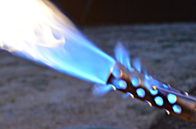
As a safety precaution, certain types of fire art installations are required to use sensors on their pilot lights. If wind blows out the pilot, the gas must automatically turn off and other valves controlling high pressure propane directed at that pilot must be prevented from opening.
Disclaimer First
This Information (web page and related hardware and software files) are provided “as is” and without warranty of any kind, expressed or implied, including but not limited to the implied warranties of merchantability and fitness for a particular purpose. In no event shall PJRC.COM, LLC or Paul Stoffregen be liable for any direct, indirect, incidental, special, exemplary, or consequential damages arising in any way out of the use of this Information, even if advised of the possibility of such damage.
My hope is you’ll find this article interesting. If you do make use of it, remember it’s something you found for free on the Internet. Ultimately it’s your responsibility to manage and accept responsibility for the risks of any project you build.
How To Sense A Flame
There are at least 3 ways to sense fire.
- Infrared Light: If you search for flame sensors and Arduino, nearly all tutorials and inexpensive products use a simple IR diode or photo-transistor circuit. Infrared light also comes from many other natural and man-made sources, making this approach very difficult to implement reliably. The absolute last thing you want in this application is a false reading allowing high pressure propane to flow!
- Heat / Temperature: Thermocouples and Thermopiles are commonly used in water heaters and gas fireplaces. However, temperature sensing can be quite a challenge for an outdoor application exposed to wind and made with metals that can remain hot for quite some time.
- Conductivity / Flame Rectification: Modern gas furnaces use this highly reliable technique. Gas flames are conductive and act as a rectifier, similar to a diode. The rectification effect is supposed to be due to a difference in the mobility of the positive ionized particles (burning fuel) and free electrons. Applying a voltage to the flame can move the electrons much moreso than the positively charged ions. The best explanation I’ve found is in this paper by Andreas Möllberg.
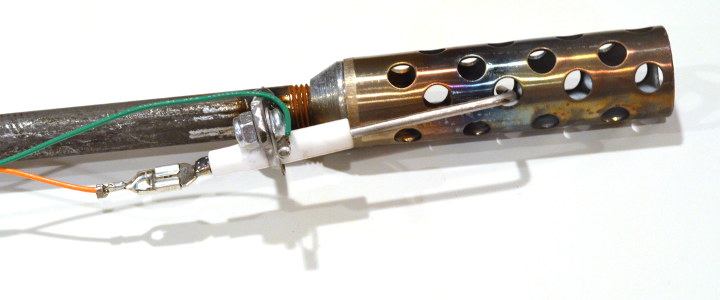
Martin had already purchased this flame sensor rod (Rheem 62-23543-01), based on the fact that it’s the sensor used in a common furnace, that it has a convenient L-shape which works nicely for his art’s pilot light design, and that it’s only $7. So the path of flame rectification sensing was chosen…
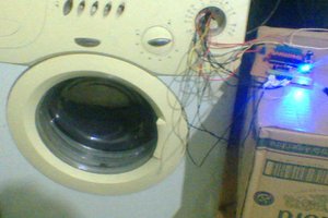
He also rigged up 1 of the Three Wishes pilot lights to a regulator and fitting so I could run in in by back yard from my barbeque’s propane tank!
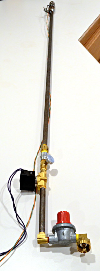
With this sensor and test gear, I started on electronics to make it actually work.
Flame Rectification Circuitry
I must confess, before this project I had never even heard of flame rectification. Reading Möllberg’s paper, it was clear the flame acts like a diode with a very high value resistor in series. Many guides exist for training furnace technicians with good info. So the basic idea is to apply a substantial AC voltage to the flame and then look for a tiny pulsed DC current.
After a couple false starts, a little more searching turned up several patents. I tried a couple of these, ultimately settling on US5439374, partly because it allows an actual analog reading (many circuits are just flame vs no-flame indicators), and partly because it expired in 2013.
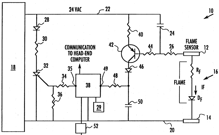
US5439374’s basic idea is current can only take 2 paths to get to the flame, either through capacitor #24, or through the resistors and transistor. Since capacitors can only pass AC current, if any net DC current flows through the flame, it must also flow through the transistor’s base-emitter junction.
An amplified copy of the DC current flows through the transistor and diode, causing capacitor...
Read more »

 Jose Ignacio Romero
 Rudraksha Vegad
 Lucy Fauth
 KingOfKYA(Travis K. )
Awesome! Glad to see you've made lots of progress!