 MrWunderbar
Features:
- Fine Adjustements (10 mV)
- Current Limit (0 - 1A)
- Small, portable
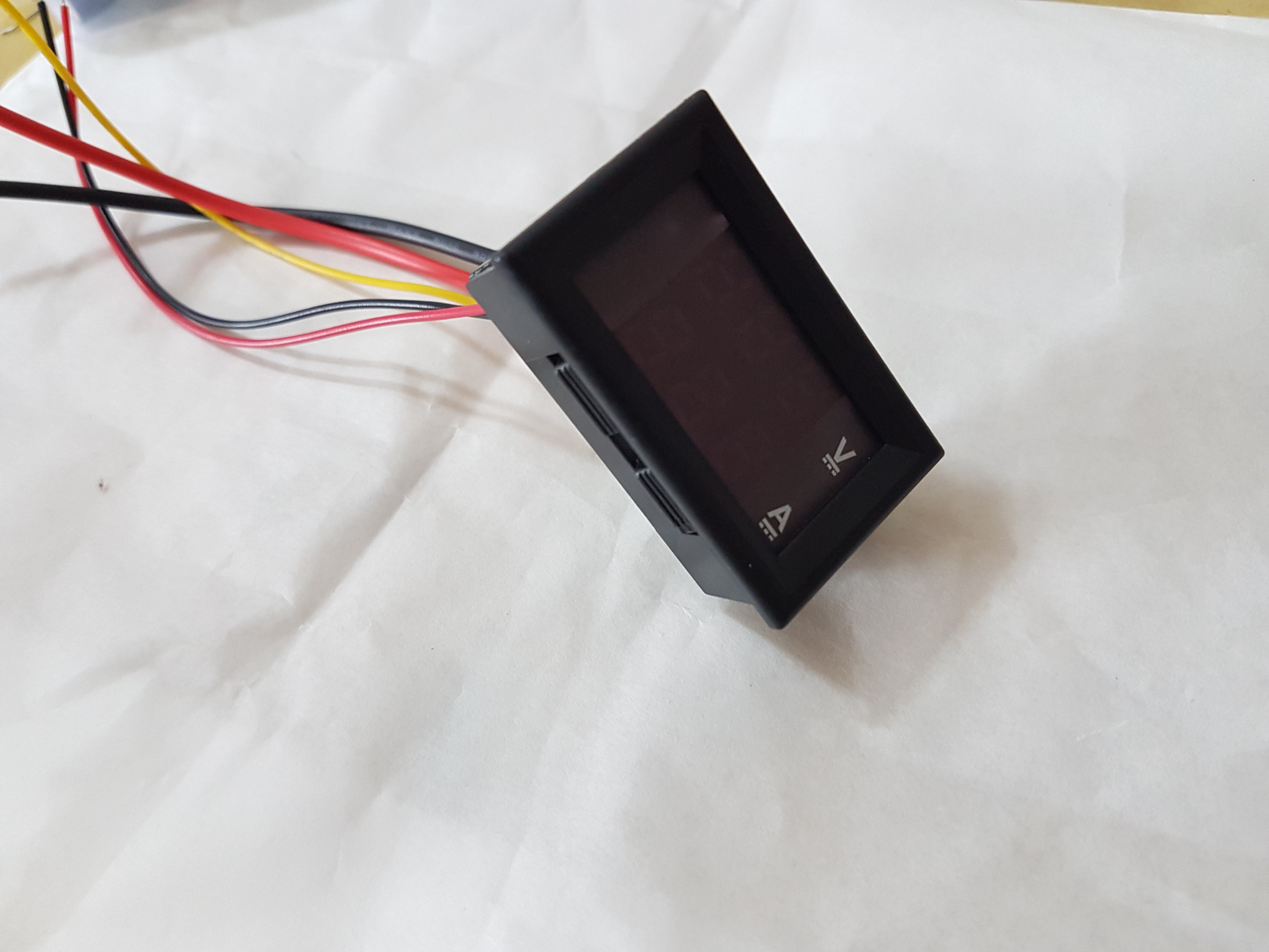
- Integrated Meters: Source Voltage, Output Voltage, Output Current, Current Limit
- Analog Design (not controlled by Microcontroller)
- digital Design
- non isolated (maybe make a bench version which is isolated)
Inputs:
- USB Power (5V)
- Banana Plugs (5 - 12 V)
- Terminal Block (5 - 12 V)
Outputs (0 - 10 V)
- Banana Plugs
- Terminal Block
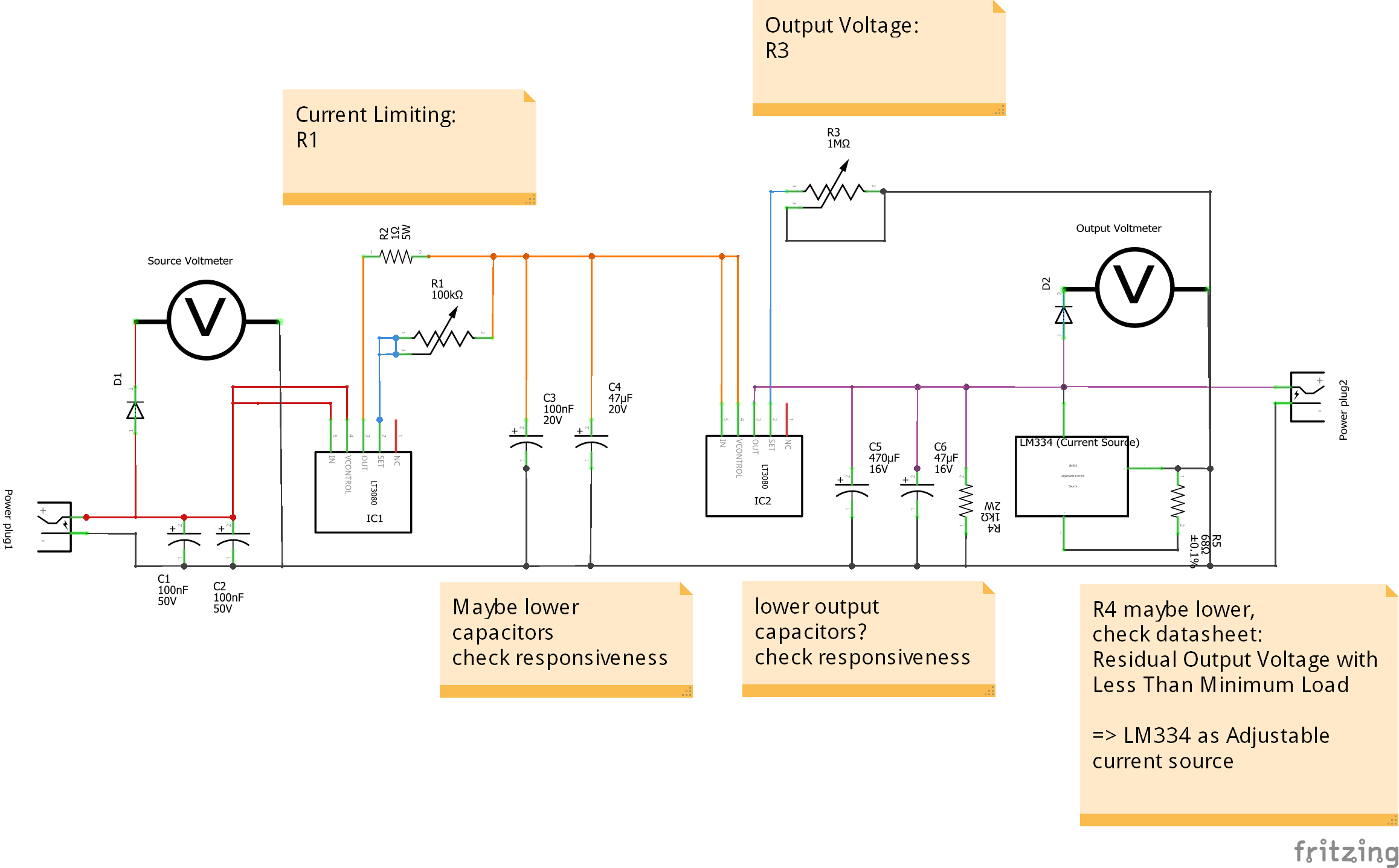
Based on this design:
http://www.microcontroller.it/english/Elettronica/Progetti/alim3080.htm

 Bud Bennett
 Paul Andrews
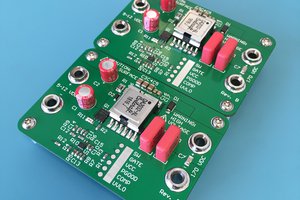
 James Wilson
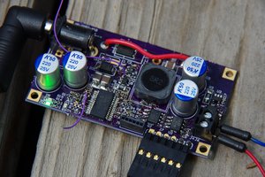
 Jonathan Bruneau
Hi,
I cancelled this project, because of two reasons.
Firstly, there were design flaws that I don't remember in detail anymore. But overall there were issues with heat generation (probably solvable) and also issues with the LT3080 in the ranges 0-1 V and above 9 V. There was also an issue in getting good current readings and current limiting. I think other people here have made much better circuit designs that are worthwhile to copy (https://hackaday.io/project/23249-digital-battery-operated-powersupply).
Secondly, there are now much cheaper pre-made solutions available now, especially the RD6012. This is almost exactly what I was aiming for when I wanted to design a digitally controlled power supply.