Time to connect everything!
Since I'm using a CNC shield, connecting is relatively straight forward. All the pins are labeled (except for z endstop and spindle rpm being reversed) and the connector type is already decided. But there are things to consider. First of all: shielding. I'm using shielded cables for the stepper motors and limit switches. But shielded cables only work if connected properly. I grounded my cables to the enclosure, as I believe this to be correct. Unfortunately proper EMC cable glands are quite expensive, so I just purchased some cheap brass cable glands and did the following:
Peel another cable with braided shield, and remove a section of the braid.
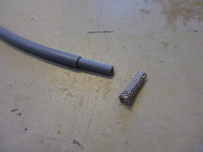 Put this on you other cable and peel a short section just inside the cable gland.
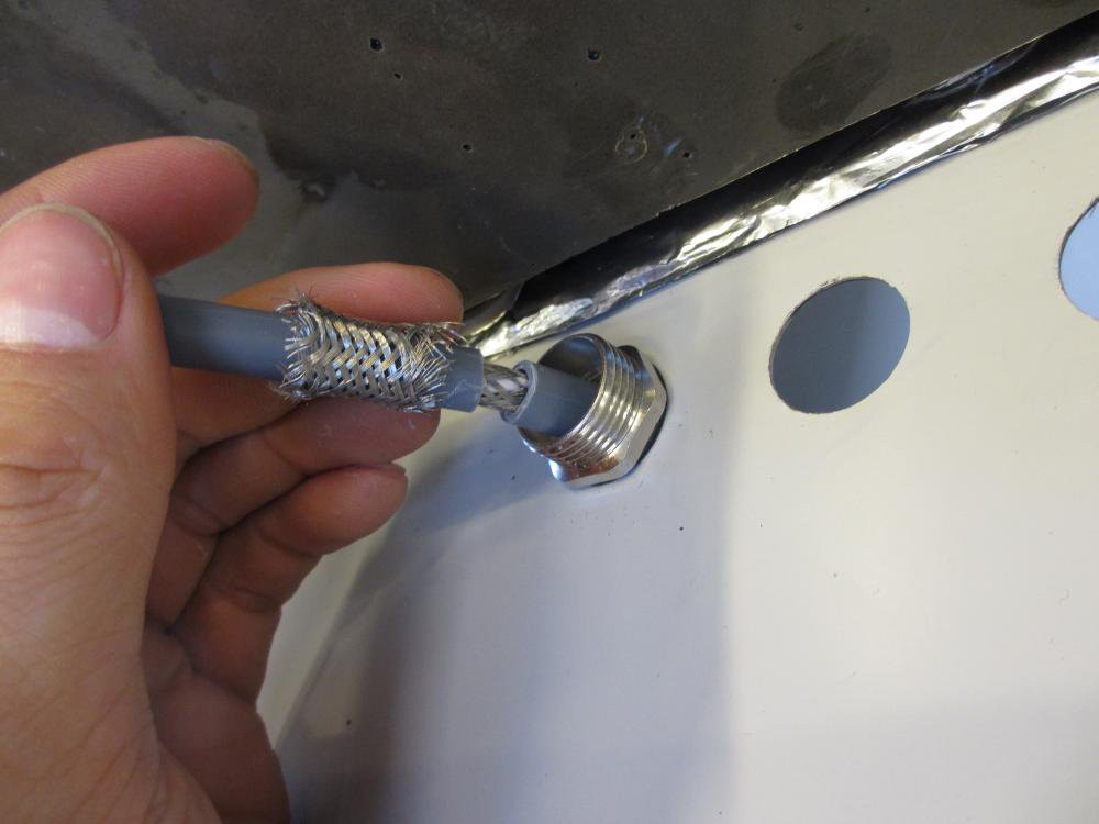
Fasten the loose braid firmly to the cable braid with a piece of steel wire and flatten it.
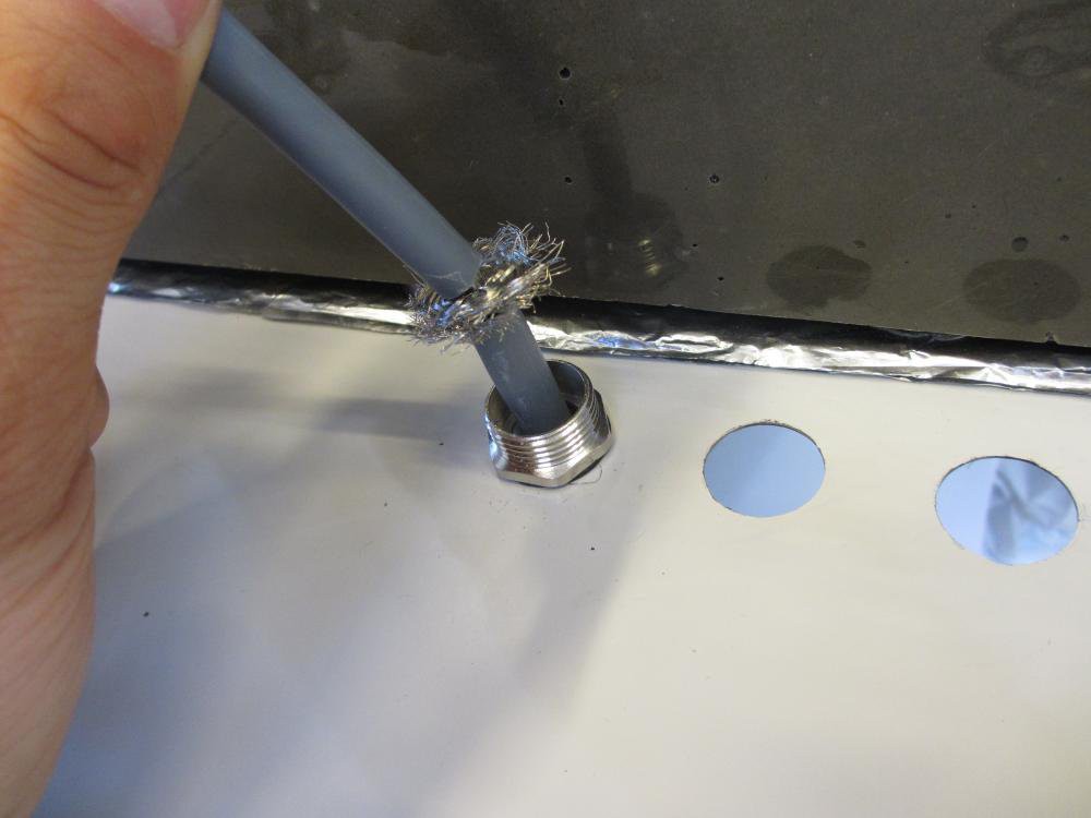
Press this down the cable gland fasten it.
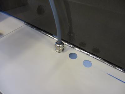
And there you go! A solid ground connection for your cable. Just one thing missing: obviously the cable gland in turn must be well connected to the enclosure. To this end I made a tool to remove the paint around the hole on the inside.
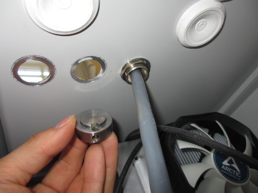
A lot of pictures wasted on something seemingly insignificant. But proper grounding of shielded cables is important! Or so I've concluded based on my finding on the subject. It's not like I'm really an expert, I'm just a mechanical engineer after all...
Another neat option is to use GX16 or DIN connectors and sockets where the cables enter the enclosure. This provides ground while also making it easy to disconnect or change cables. I did this with some cables, and in hind sight I wish I had done it on all cables.
Next up: installing limit switches. Here's a picture of the x-y cross slide with limit switches installed (only missing the cams for the y-axis on this picture).
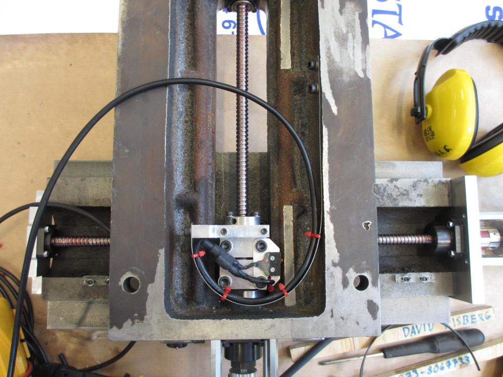
The Z-axis limit switches look about the same.
Next I decided to improve my stepper drivers a bit, to get as much performance as possible out of the puny DRV8825. I soldered a big sheet of 0,3 mm copper to the thermal vias on the bottom, and also soldered some whiskers to the current sense resistors since these are a bit underrated for the application.
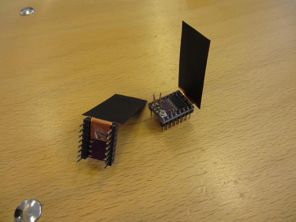
This helped, but even with all this I was not able to get up to the specified 2,5 A that the drv 8825 should be good for. In fact i was still stuck at about 1,8 amps before overheat protection kicked in. After adding a powerful cooling fan I could turn it up to 2 amps. Maybe I can go higher, but measuring the amps and tuning the pot was a bit of a hassle because of my huge heatsinks being in the way. Maybe I'll get back to this later, if I don't scrap these and go for some real drivers. Or servos. The reason for this disappointment could be that the thermal vias are not fully filled with tin on these cheap boards. Maybe the themal sink of the driver isn't even properly soldered to the board? Or maybe this is normal when using 36V power supply and steppers with low resistance? Feel free to comment on this if you have some useful experiences.
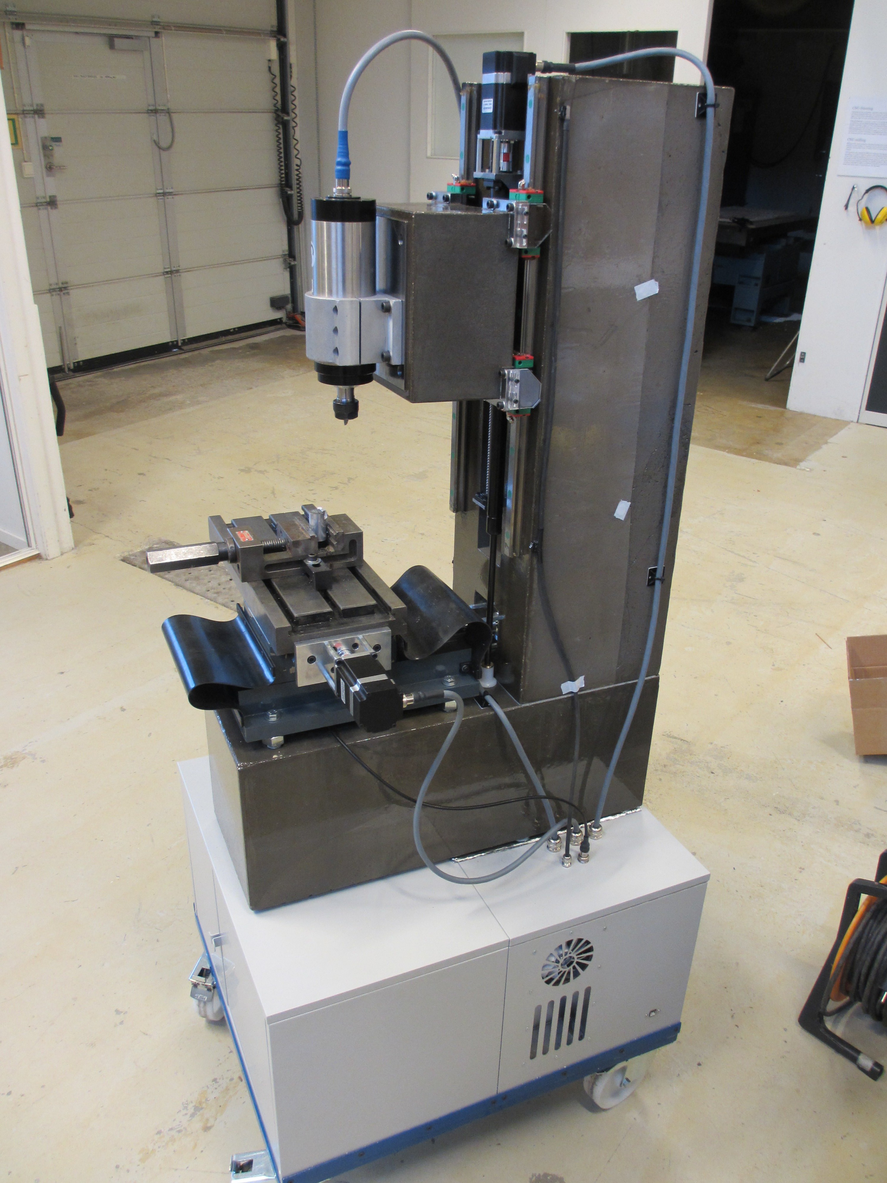
Anyway this is how my electronics enclosure looks like today (plus a 12v power supply and a cooling fan over the drivers).

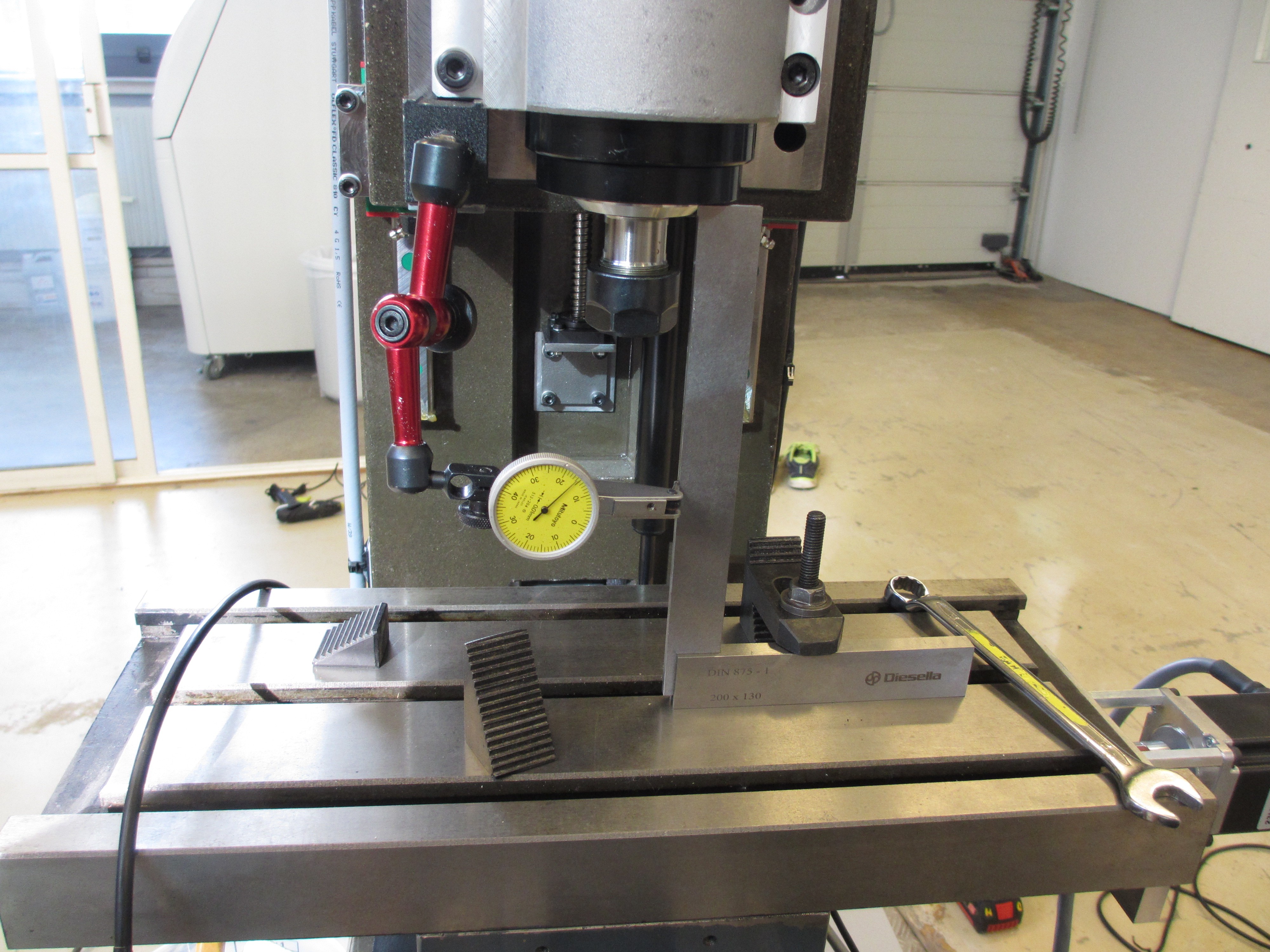
After this I started to tram and true the machine. I also tuned the control system, and was disappointed by the feeds I got. I can only seem to get my steppers up to about 560 rpm. Maybe this i normal but that means only 2250mm/s with my 4 mm pith ball screws. Nothing to do about that now though...
Then I immediately proceeded to break my first end mill.
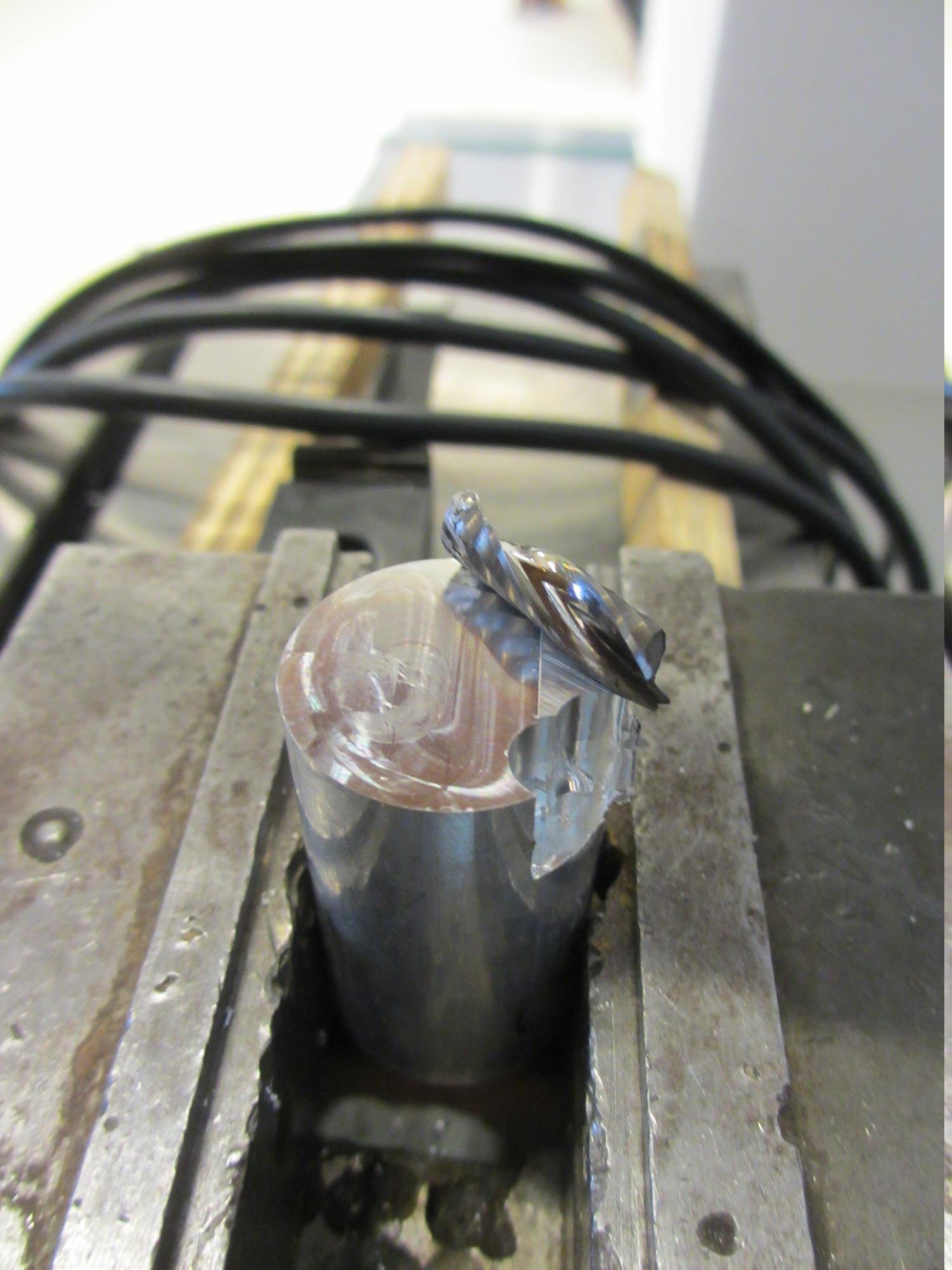
Being new to fusion 360 it seems i failed to export the roughing cut and exported only the finishing cut. This is what you get...
But I also decided that my rails and ball screws are much to exposed to contamination while machining, so I'll finish the way covers before I do any more machining. The X-axis needs no protection since it is on the underside of the table and thus already protected. I protected the Y-axis with the simplest possible means, as illustrated in this picture (the rubber sheets):
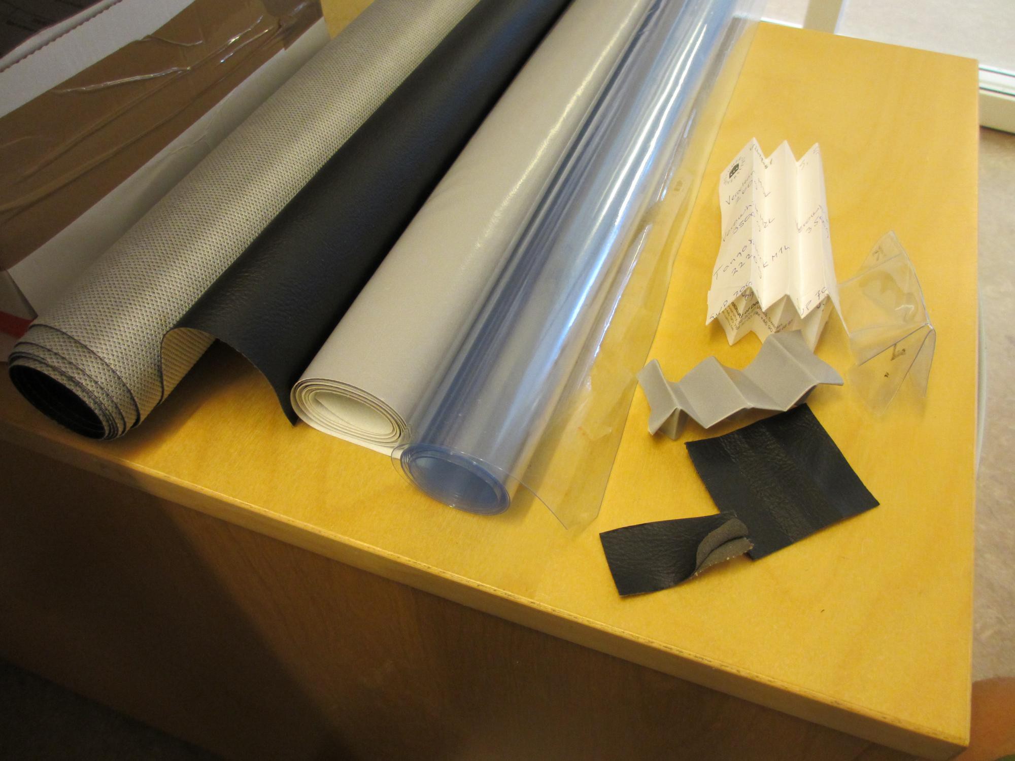
For the Z-axis I'll make some custom bellows. Here's a teaser where I'm testing some materials and fold patterns:
Next update in a few weeks I hope....
Discussions
Become a Hackaday.io Member
Create an account to leave a comment. Already have an account? Log In.