 Marcel
Chasis
- a usual 'Rothaus' beer case
- modified to fit the electronics inside one of the walls and the LEDs at the bottom (without loosing robustness)
- 3D-printed plug for sealing the side wall with the electronics at the bottom
- aluminium bars at the top for opening beer bottles
- sprayed with weather-proof paint
Hardware
- ESP8266 on ESP-01 board
- self-made PCB with 5V-to-3V-regulator and button
- WS8211 water-proof LED strip with 60 LEDs per meter
- slim USB power bank from Amazon (has to fit in the side of the beer case)
Software
- https://github.com/tcm-marcel/wanderkasten2
- Arduino based firmware
- FastLED library, especially the inoise8 and blend functions
- webinterface redirection inspired by WifiManager implementation
- built with makeEspArduino
- added target to minify html files and convert them to a header file containing the file as byte array
Problems
- originally the possibility for OTA (over-the-air flashing via Wifi) was planned, but ESP-01 has not enough flash memory
- due to a design mistake one pin of the voltage regulator was not connected on the PCB and had to be bridged
- removing parts of the bars in the inside to make space for the LED stripes was much harder than expected because they are really hard to reach, it took us hours
 top view at night
The build process in pictures
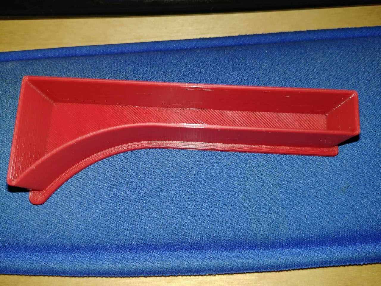 the 3D-printed plug that will cover one edge of the case from the bottom (thanks goes to Janosch)
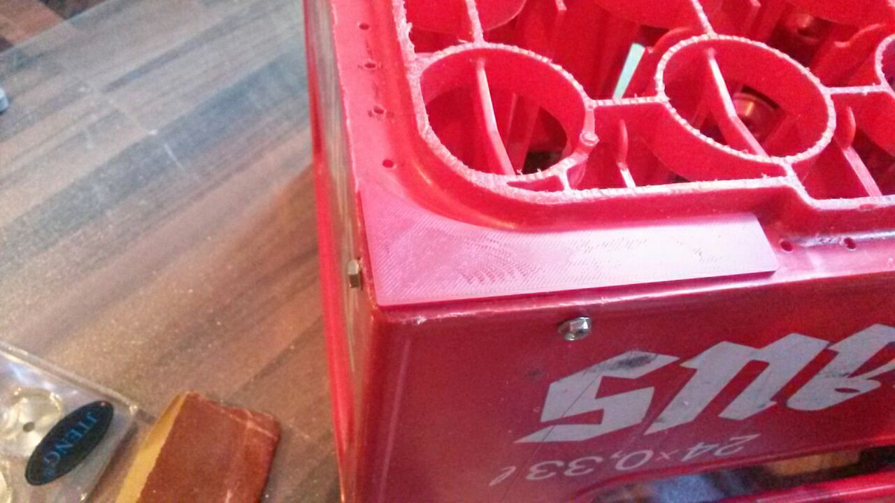 early checking if the plug fits (yes, it fits!)
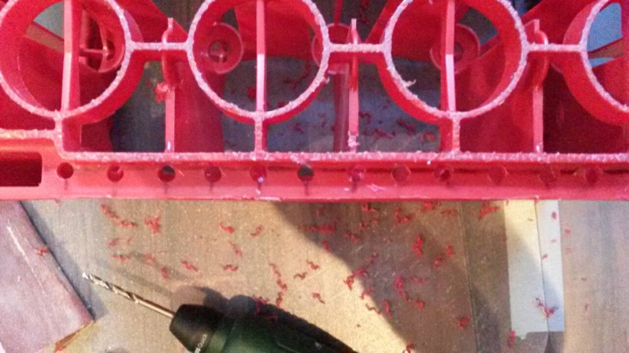 drilling the holes where later the LEDs of the stripes will be, the bars which still have to be cut can clearly be seen
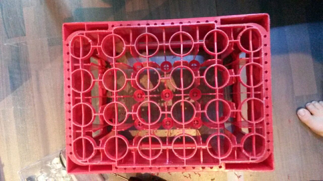 bottom view of the case after drilling all the holes and removing the bars inside the side wall
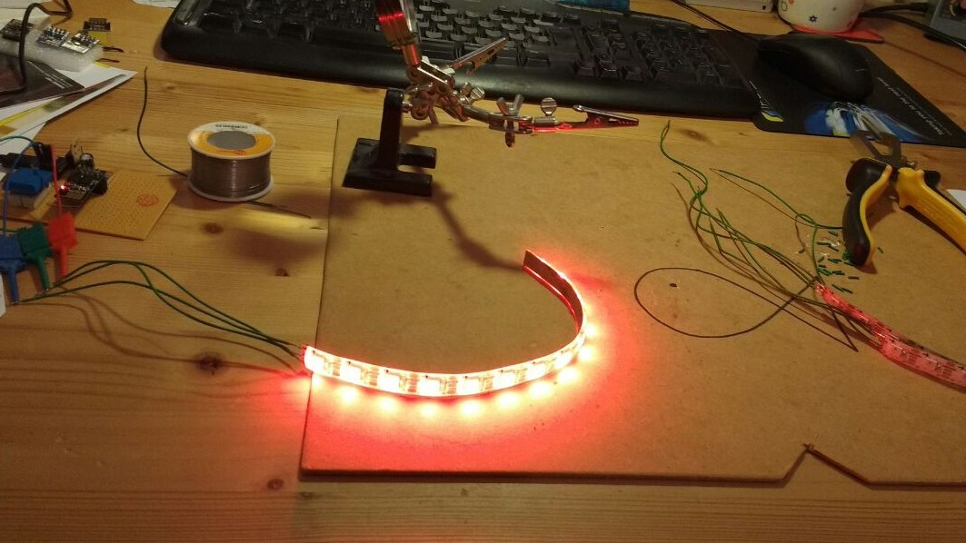 preparing and testing of the four LED strip parts. later capacitors for the data line and heat-shrink tubes will be added.
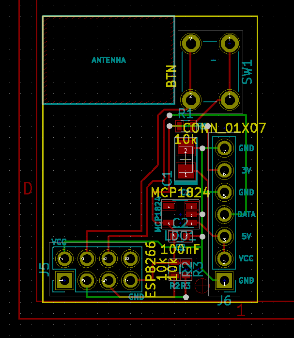 design of the PCB in KiCad
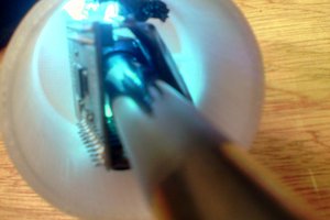
 PCB with ESP-01 (the final one was soldered directly to the PCB)
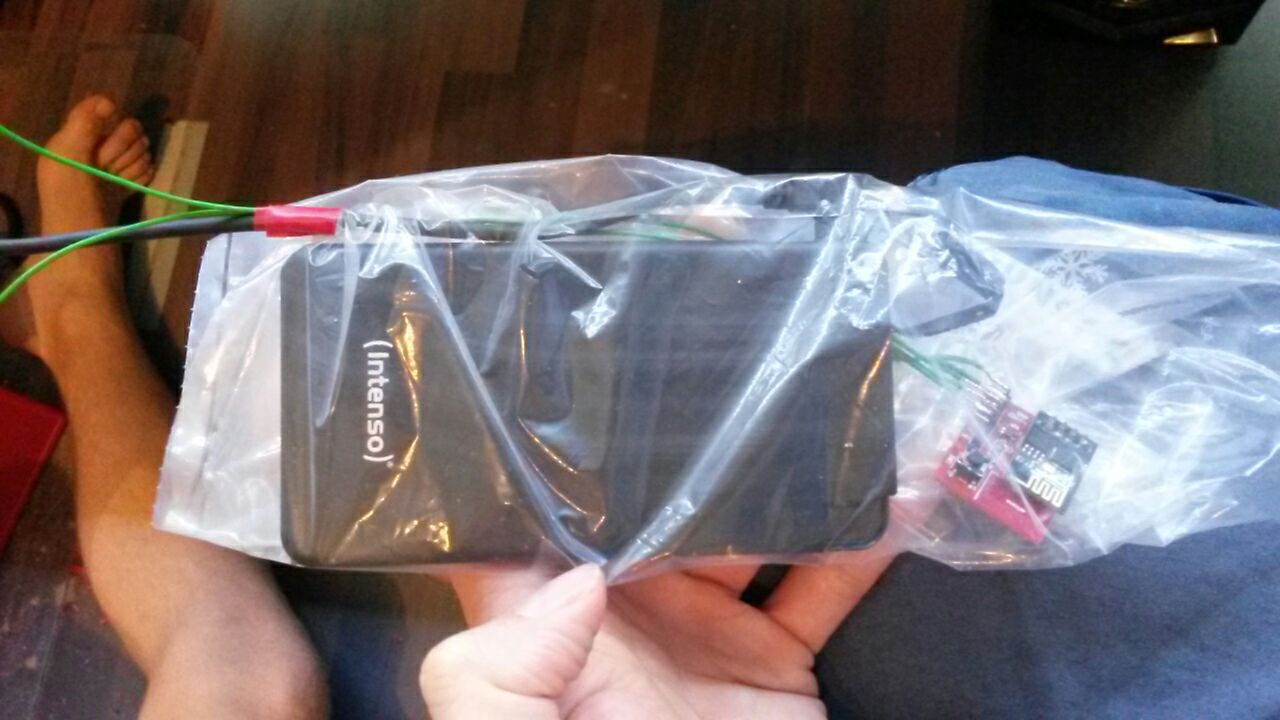 the powerbank and the chip inside the water-proof bag before inserting into the side wall, at the top the micro-USB cable and two wires for the switch can be seen
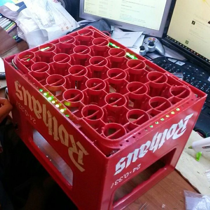 bottom view after connecting all LED stripes but before adjusting their position to fit the holes
 view of the edge containing the electronics after inserting them and connection the LEDs
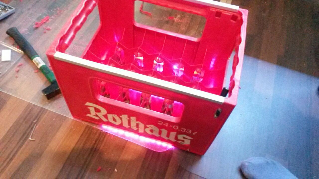 the final case before getting painted, the electronics are already inserted into the side wall, the switch is connected and the aluminium bars are mounted
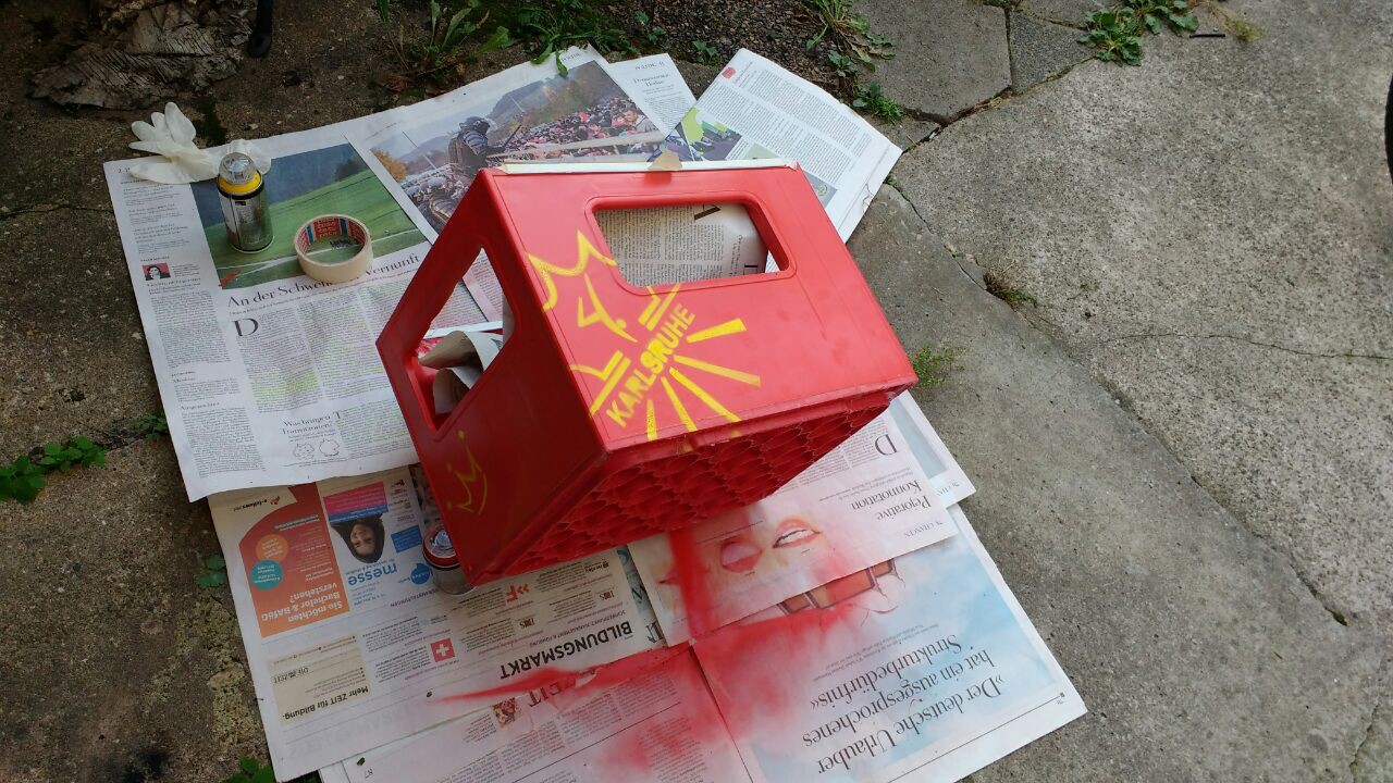 spray-painting the final case
 foulum.mosegaard
 sjm4306