 Pavel
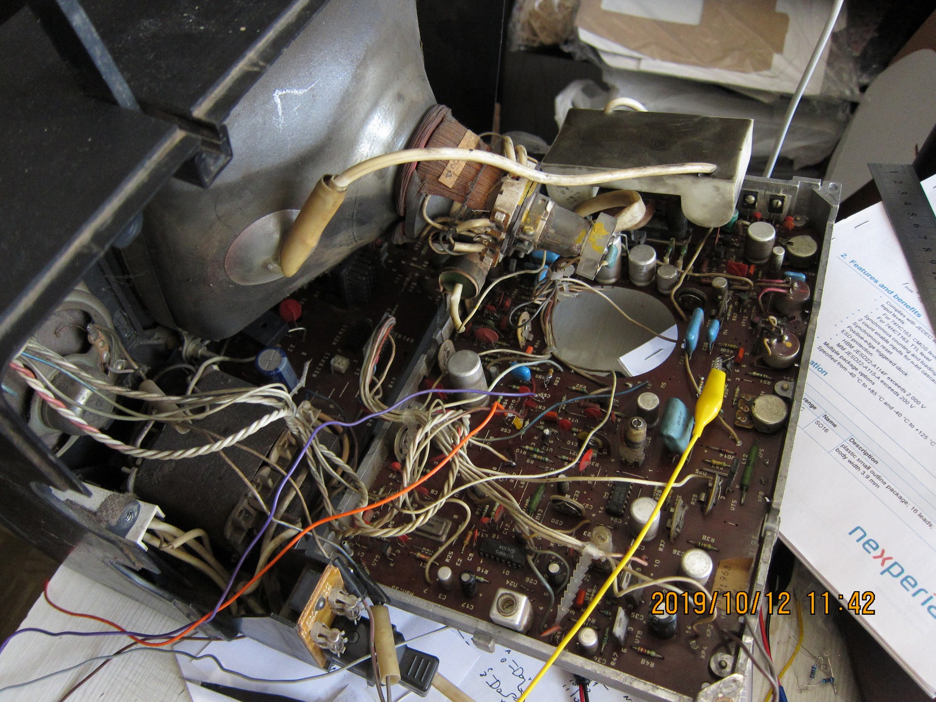
PavelA couple of months ago I've dug this TV up again and played with it, using the generator from previous log, trying to measure signals inside the TV to understand what is going on. Unfortunately at one time I shorted something and fried some chips in the generator - those became very hot; afterwards the signal generator was no more outputting any periodic signal, just constant high or low on different leads.
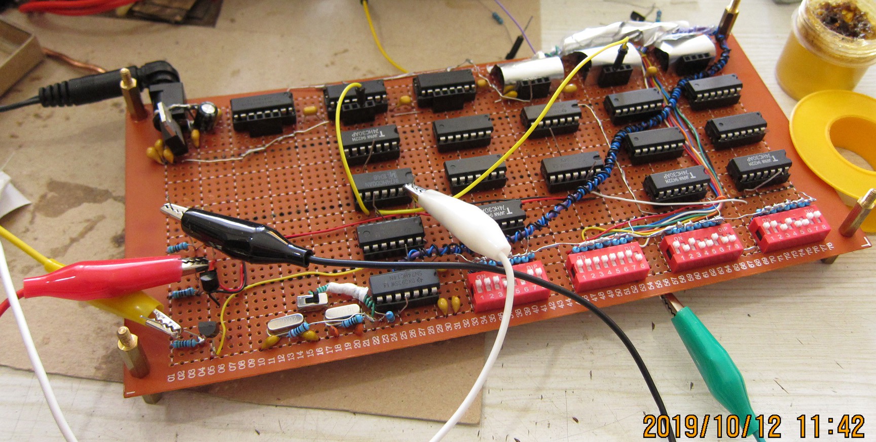
Thus the need for a new generator arose. This time I made it more adjustable -- one can set start of horizontal blanking interval, timing of vertical and horizontal sync pulses, and horizontal line time with switch banks.
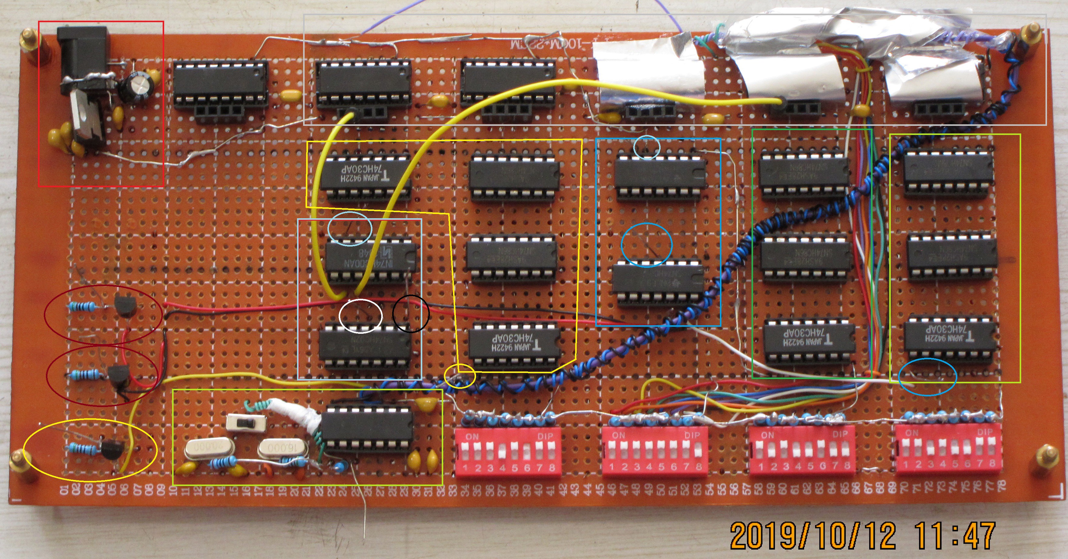
On the picture above, top row is made of only 74hc163 4bit synchronous binary counters (grey box), and mentioned switch banks are red at bottom.
In between there is logic needed to facilitate adjustment (XOR and NAND gates -- two 74hc86 and one 74hc30).
Functional blocks are inside rectangular shapes, ellipses indicate output/test leads.
Functional parts by colour:
In red box is the power supply -- 7905 IC with capacitors.
In grey box is the counter which provides all timings by dividing the clock signal. Actually, it is in two parts - one counts to 1024 clock cycles for line timing, these are the 3 rightmost ICs hidden under foil; to the left is line counter which provides timings for frame. It counts up to 256, so there are 256 lines per frame total. 216 of them are used for image (intended to be only 200, but I've got my calculations slightly off and soldered some wire in the wrong place).
In the light-green box on the bottom-left, near switches, is the clock circuit, uses one of the two quartz crystals (16MHz and 20MHz) - this drives the counters. Main clock is 16MHz, as this gives base line time of 64 microseconds, or frequency of 15625 Hz, which is perfect fit for the TV. Due to having less lines than standard PAL signal (256 vs 312), this gives me 61 frames per second. The tv seems to be fine with it. The 20MHz is experimental, it boosts line frequency by 25%,and it seems like it is on the edge of what tv can handle -- the picture is fine at first, but after a minute or two starts to distort.
From right to left:
In rightmost light-grey box is the sync signal timing adjustment, one can use it to adjust when this signal is after start of the line. It has one output lead to check the signal is right shape on oscilloscope.
Next to it, in green box is adjustment of start of line blanking interval.
In the blue box are two 74hc00 ICs. On one of them two gates wired as SR latch, which generates blanking interval from Start of Blanking and Start of Line signals. Checked on lead in light-blue circle. Other gates are used to generate crude test signal from this blanking and carry out from the rightmost 74hc163 counter - checked on lead in blue circle. Yet other gates on these ICs are forming complementary signals for line sync circuitry - they come off to a red/black pair of wires.
Yellow shape contains circuitry needed for Vertical sync adjustment.
Light-blue box has another SR latch, forming Vertical blanking interval. Other gates are wired to combine Vertical, Horizontal blanking, and two other inputs, which are picked off by two yellow wires. The wires have pins which can be inserted into headers next to counters. This way a grid of rectangular shapes can be created on the screen. Sizes of the shapes are 2^n dots x 2^m lines. The white and black circles are complimentary outputs, one gives white rectangles on black background, while another is black rectangles on white background.
The transistor-resistor pairs are essentially RTL invertors, used here to interface between 5V level of this board with ~12V voltage used by TV's circuitry.
The wire from clock circuit to counters has wire with complementary signal wound around it, and another wire which is connected to ground, to make some shielding from EM interference. The dot counters are also covered with Aluminium foil (sandwiched between Scotch tape) to reduce interference pick up. Without this cover the counters worked erratically, by just moving hand around them, without touching, caused them to stop, or start counting.
The switch bank with bunch of wires coming from it to counters ( 3rd from the right) is used to adjust line length, by pre-setting the counters. Dot count can be adjusted to be from 0-1024 to 256-1024. This influences timings by shortening line time, making line frequency higher. Thus line frequency can be adjusted by small increments.
The purpose for pursuing higher line frequencies is twofold: making frame rate higher, thus reducing flicker, and to get rid of audible high-pitched whistle coming from TV's flyback transformer. At 15.6 kHz it is quite loud, very noticeable and annoying, while closer to 20kHz one has to be in very quiet room to notice and hear it. The audible noise can be analysed with nice little Android app called "Spectroid".
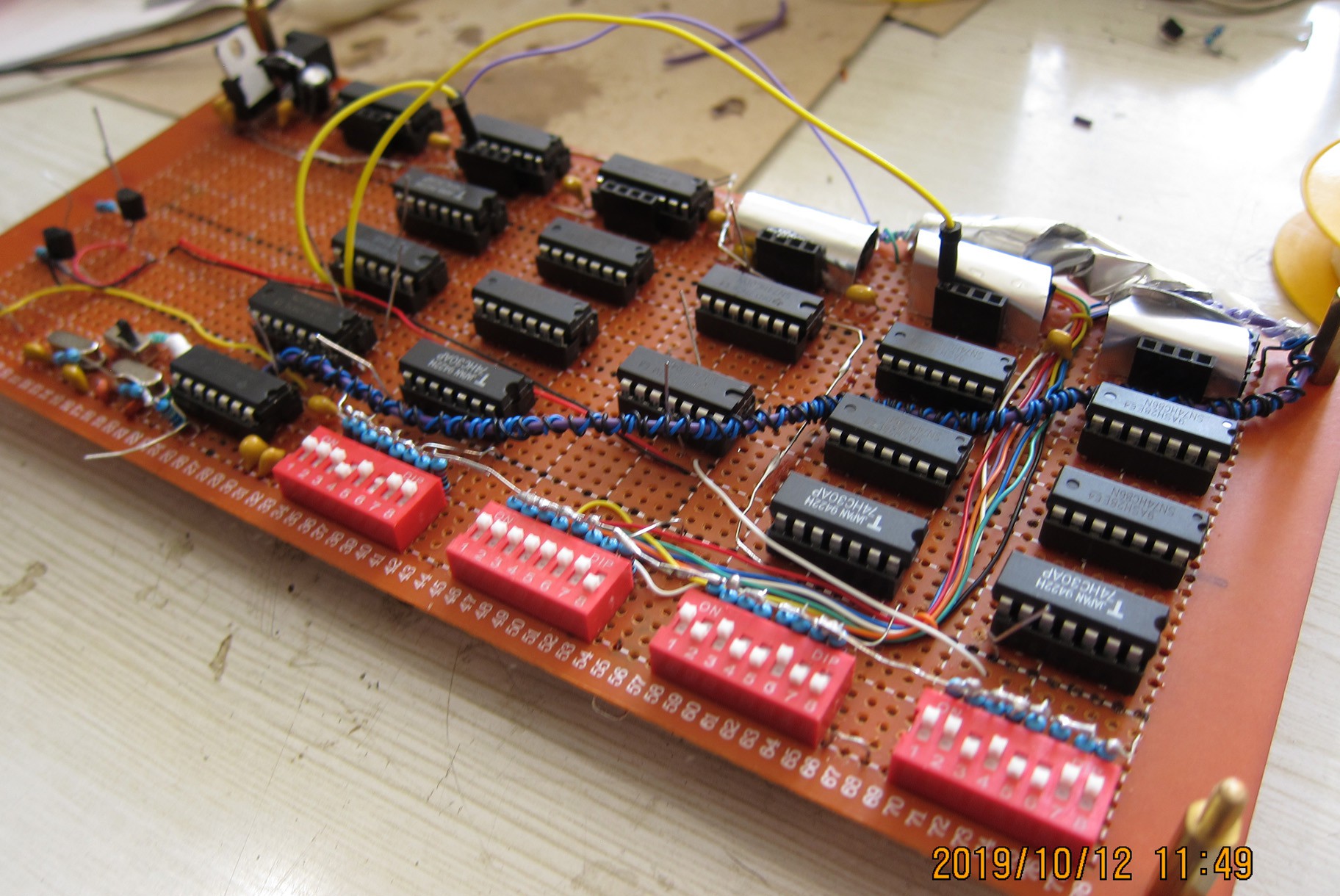
The board looks quite nice from the top:
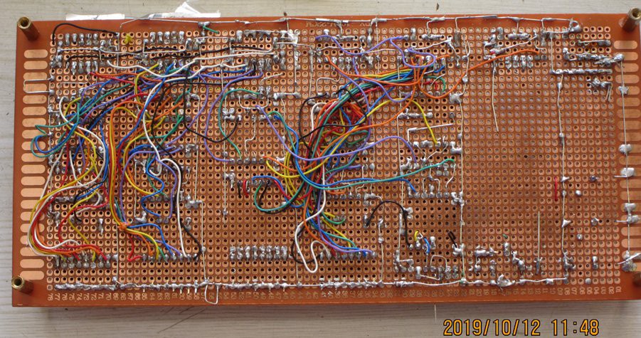
Not as much from bottom =)
The board is not fully finished, it needs at least a decent connectors for output signals. As of now, the connections to TV are through Alligator clip wires (my place i such a mess):
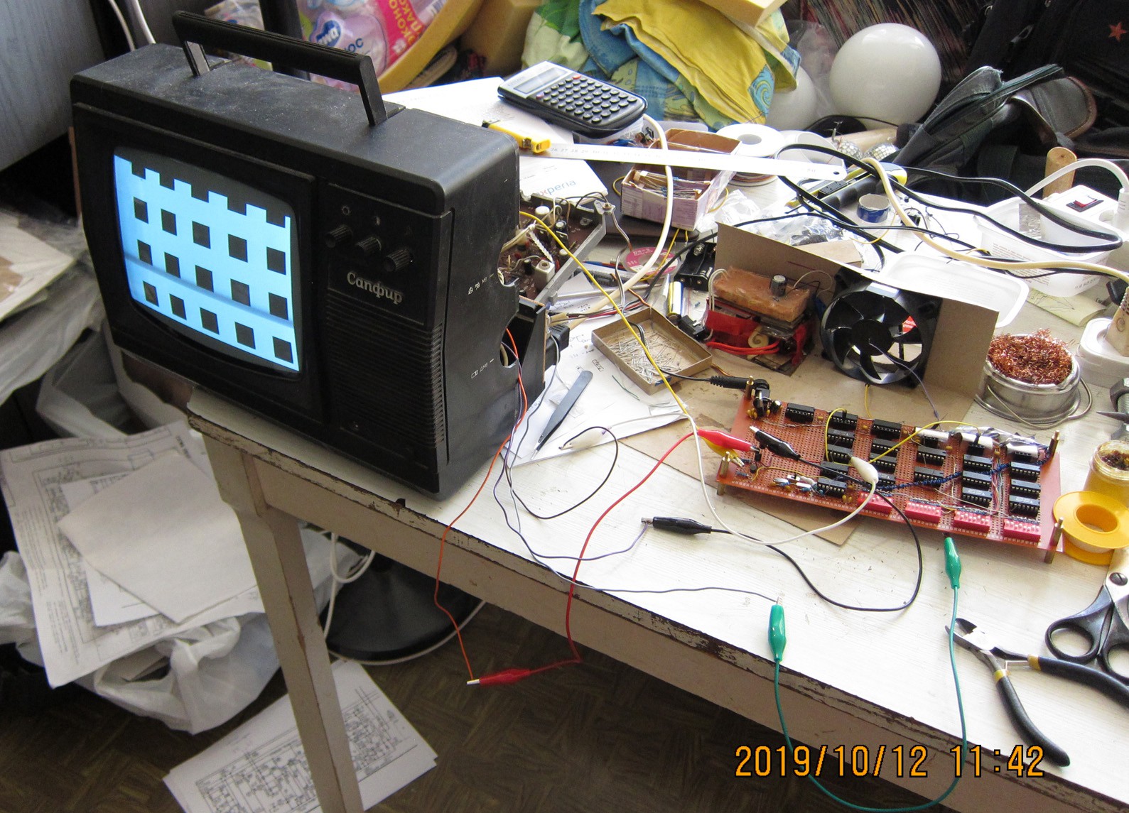
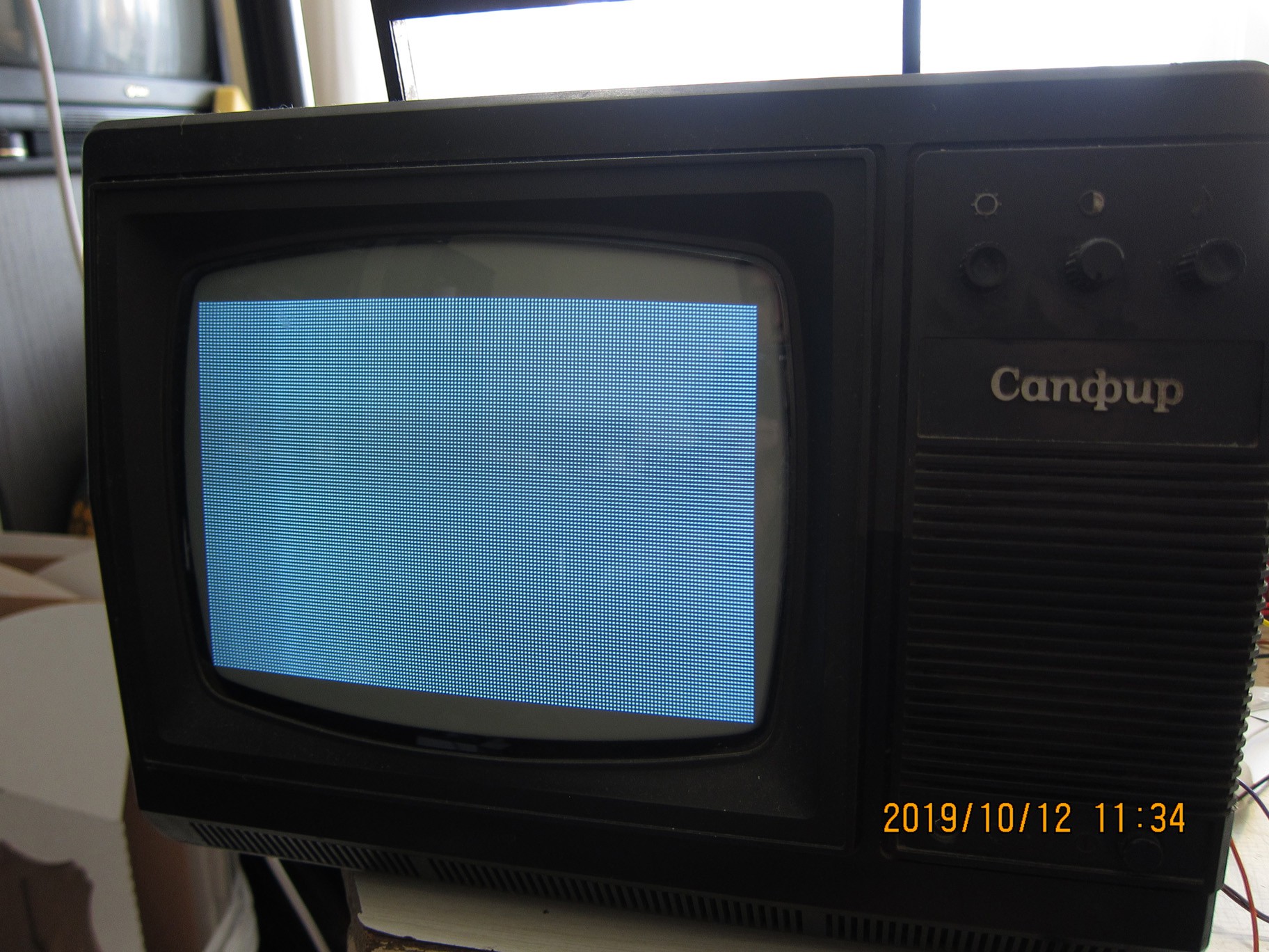
Some patterns:
smallest pitch readily discernible: 2 clock cycles on/ and 2 off, on even lines. So 2 clock cycles = 1 pixel:
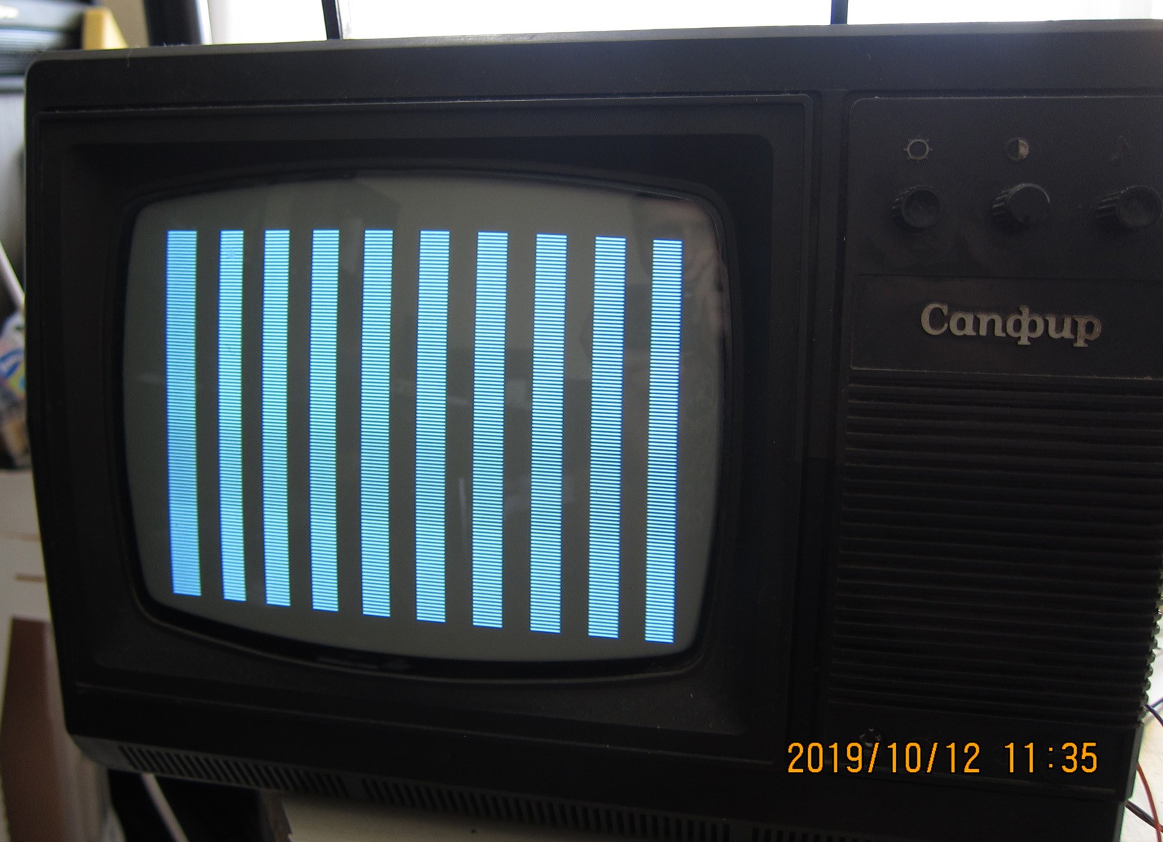
Some bigger (16x1 px):
8 by 8 px squares:

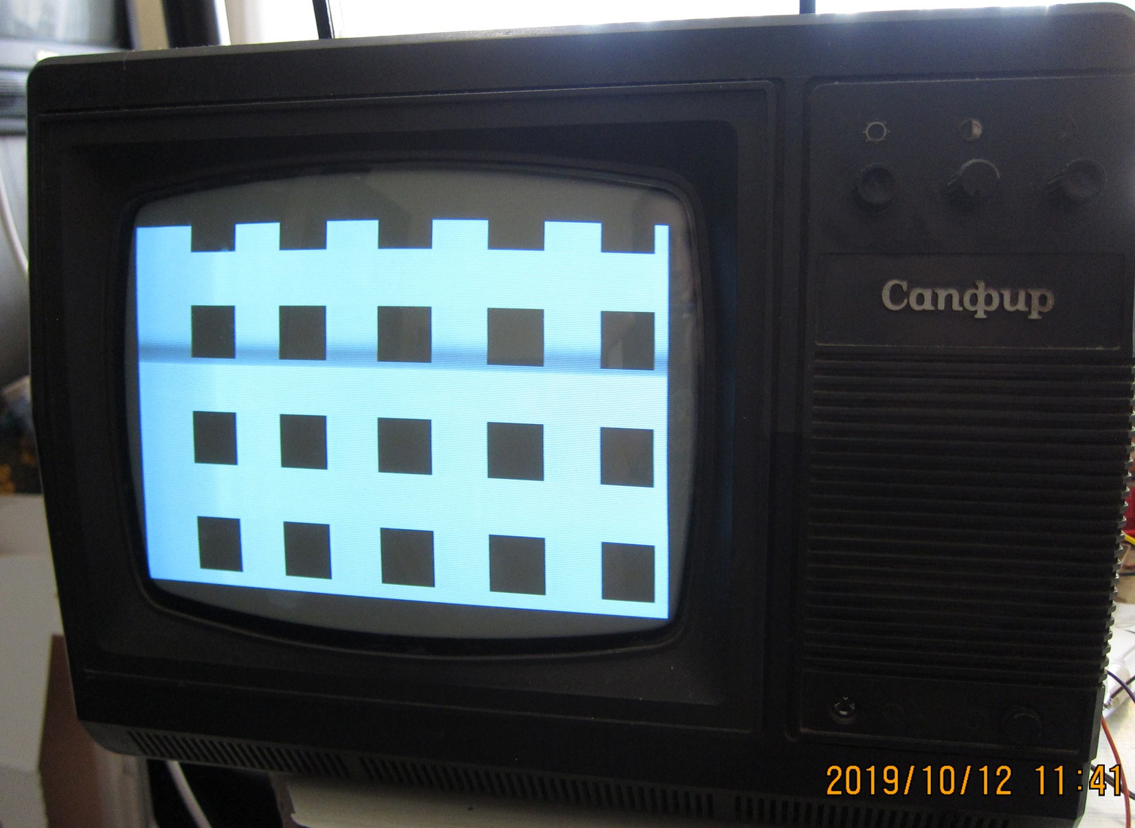
Some big black squares (32x32) on white background:
The size of image on the screen is 320x256px, progressive scan, 61 frames/second on PAL tv (heavily modified).
Discussions
Become a Hackaday.io Member
Create an account to leave a comment. Already have an account? Log In.
Do you think it would be able to display 512*256 pixels in 4 intensities? https://hackaday.io/project/176081-tim-011-fpga-based-vga-and-ps2-keyboard-adapter/log/186518-tim-011-video-signal-generation-grafika-component
Are you sure? yes | no
With different signal generation circuit it may have been able to display even 256 intensities at that resolution.
But with the one presented above, it is only black or white, and nothing in between, and only rectangular patterns. It was intended as testing device, to determine the resolution and blanking intervals at which the image is fully visible on screen, and stable. This turned out to be 320x256px.
I intended to make it a little text terminal, but I haven't followed through with this plan, there were several reasons:
- the image had persistent distortion, a quarter way from the left, it was squeezed, so the squares were vertical rectangles, while at the right third of image, the squares were stretched into horizontal rectangles;
- the image was constantly slightly wobbling, and its size was varying with overall brightness of image;
- Making line frequency higher (moving towards 20kHz) turned out to be impossible - the image was desintegrating, with static and loud noizes, as this small TVs flyback transformer could not work in such regimes
- The TV is still fairly heavy and bulky, so I abandoned it when I moved recently.
The circuit now is used sometimes as square wave generator of different frequencies, and chip donor.
Overall, this is fairly old project, which I no longer working on.
Are you sure? yes | no
Thanks for the thorough reply, it is still pretty fascinating what could be achieved with 30 year old B/W TV set. Probably a bit more high end TV could be adapted.
Are you sure? yes | no