IDE installation
Initially I had a problem with the IDE (on 64-bit Ubuntu 16.04) in that I couldn't connect to the board at all. It turns out that you have to manually run a script to set USB permissions, and the location of this script is not as documented. I had to do this:
sudo ~/.arduino15/packages/Intel/hardware/arc32/2.0.2/scripts/create_dfu_udev_rule
After this, everything ran smoothly! I wrote the code to implement a basic menu controlled by the two buttons (the pushbutton and touch sensor), and I used the serial console to display debugging information.
Here is the stack with power connected and the LCD backlight set to green:
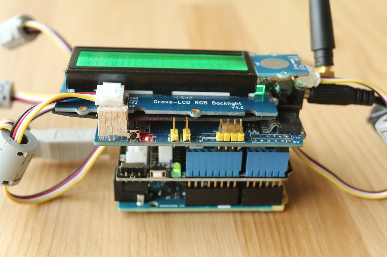
At the top level menu screen, the push button acts as a panic switch and the touch sensor cycles through the menu options. When cycling through the options, the push button selects a menu item. The lower line of the LCD makes it clear what each button will do.
Power problems and solutions
The GSM shield can draw quite some current when transmitting (about 2A for short periods). The shield has a regulator to provide the 4.1V supply for the SIM900, and a power jack for an external adaptor that feeds this regulator. This external adaptor is fine for testing, but won't be much use for a wearable device.
There is a switch on the shield that can be used to feed the regulator from the Arduino 5V pins instead of the external jack, but the current available is not enough to support the transient peaks. I found that the SIM900 would frequently reset due to lack of power. Luckily, I found an easy solution. By adding a large electrolytic capacitor on the 4.1V line, the transients can be supported and the shield will operate fine from the Arduino 5V supply. I found that 4700uF was ample. The MIC29302 regulator doesn't seem to mind the extra capacitance on the output.
The power architecture of the Arduino 101 supports various possibilities for powering the board, including power from the external jack, the USB interface and also a direct feed on the 5V pins. Looking at the schematic, it seems to me that low dropout protection devices prevent any backfeed damage. I plan to provide 5V via this direct method, and this will also feed the GSM shield regulator.
USB power bank
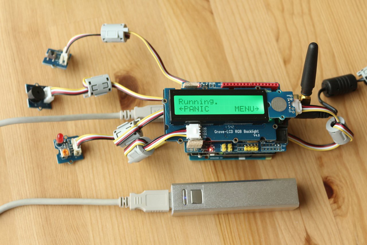
The source of 5V will be a USB power bank. This provides a neat solution as it integrates a 3.7V Li-ion cell with a power supply circuit and charger, and will allow the device to be charged up with a USB cable.
Here is the project so far, with the Arduino powered by the USB power bank. At this stage the GSM shield still has external power, as the capacitor is not yet connected. The LCD is showing the top level menu screen, with custom defined arrow icons:
GSM functions
I bought a pre-paid SIM card that offered free texts to the same network as my mobile phone. This is helpful as you can end up sending a lot of texts during development.
I found the following SIM900 references very useful:
It turns out that sending and receiving text messages in a basic way is really quite easy. The SIM card contains a few memory slots for received text messages. You can either poll the SIM900 to see if a new message has arrived in one of the slots, or you can ask to be notified when a new message arrives. I chose to poll for new messages, and the software does this every 60 seconds. If a new message has arrived, it is read and then deleted from the SIM card.
Sending a text message is simply a case of sending one AT command followed by the destination phone number and the actual message. Here is the complete function for sending a text, with the GSM shield connected to Serial1, and noting that gsmWait() simply waits until the Serial1 receive buffer is empty:
bool gsmSendSMS(int n) {
  bool result=false;
  Serial.print("Sending SMS ");
  Serial.println(n);
  Serial1.print("AT+CMGS=\"");
  Serial1.print(MOBILE_NUMBER);
  Serial1.println("\"");
  if(gsmWait()) {
    if(n==REPORT) Serial1.print("Status report");
    if(n==REPORT+1) Serial1.print("WARNING - PANIC pressed");
    if(n==REPORT+2) Serial1.print("WARNING - heart rate");
    if(n==REPORT+3) Serial1.print("WARNING - location");
    if(n==REPORT+4) Serial1.print("WARNING - fall detected");
    if(n>=REPORT) {
      Serial1.print(": HR ");
      Serial1.print(heartRate);
      Serial1.print("bpm , ");
      Serial1.print(gnssDistance);
      Serial1.print("m from home, location ");
      if(gnss.location.rawLat().negative) Serial1.print("-");
      Serial1.print(gnss.location.rawLat().deg);
      Serial1.print(".");
      Serial1.print(gnss.location.rawLat().billionths);
      Serial1.print("N, ");
      if(gnss.location.rawLng().negative) Serial1.print("-");
      Serial1.print(gnss.location.rawLng().deg);
      Serial1.print(".");
      Serial1.print(gnss.location.rawLng().billionths);
      Serial1.print("E.");
    }
    else {
      Serial1.print(TEXTMESSAGE[n]);
      Serial1.println(".");
    }

    Serial1.println((char)26);
    result=gsmWait();
  }
  else {
    Serial.print("Unable to send SMS");
    Serial1.println((char)26);
  }
  return result;
}
I decided to keep the messaging implementation very simple. The carer's phone number is currently hard-coded in the software, and there are several pre-defined messages that the user can select to be sent. Received messages are checked to see if the first character is a question mark '?', and if it is then the device will send a status response. If not, the message will be displayed on the LCD as a scrolltext. If a new message comes in, the previous scrolltext is overwritten.
The next step will be to add the heart rate monitor and fall detection functions.
Discussions
Become a Hackaday.io Member
Create an account to leave a comment. Already have an account? Log In.