 JanThar
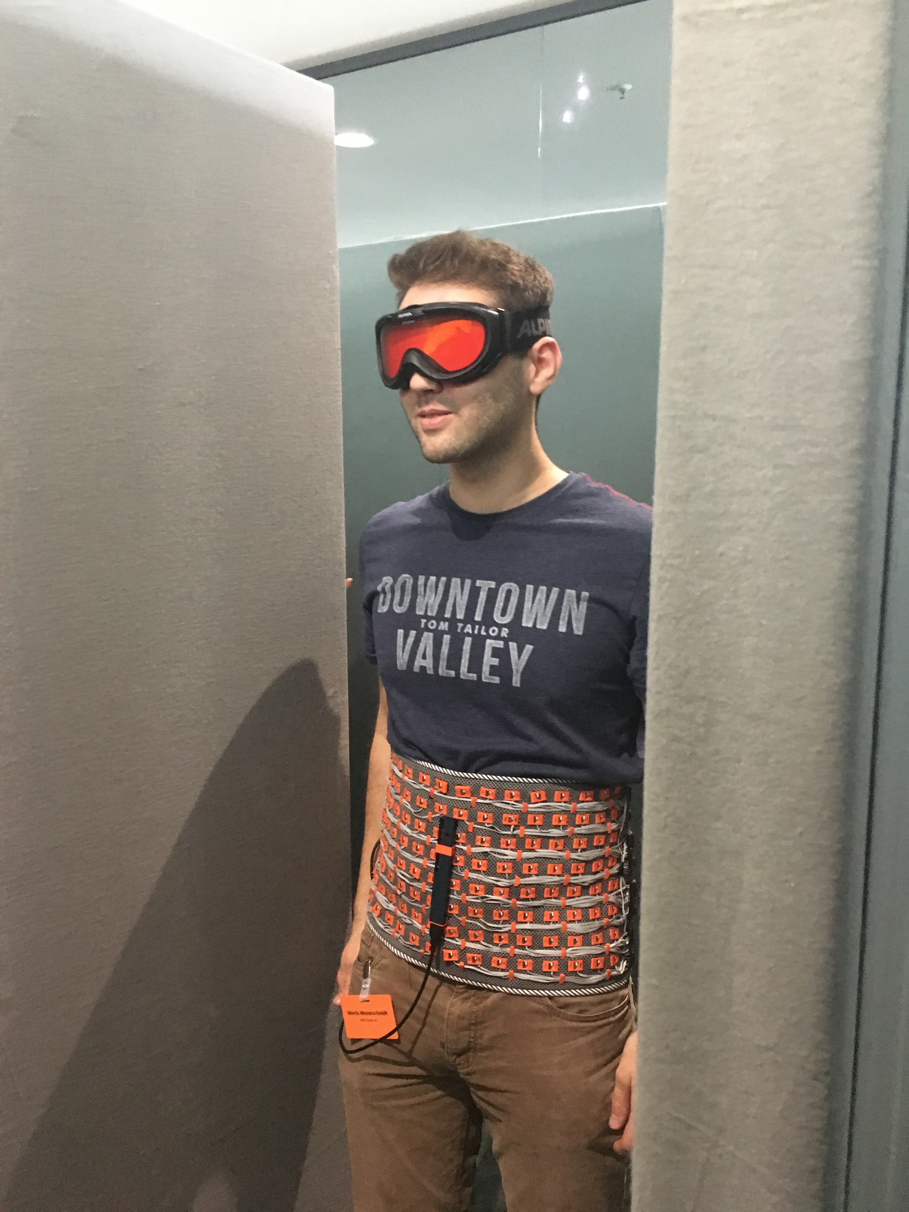
The main concept is the same as in David Benchoffs and David Sanchez vest: Using an array of vibration motors controlled by an image from a depth camera - so each vibration motor acts as an image pixal and vibrates stronger the nearer an object is at this pixel position, helping the visual impaired to get a feeling of their surroundings and know where to go and where not.
Since the vibration motors can be worn under the clothing, the system is (normally) invisible besides the sensor system, and uses with the abdomen an otherwise unused sensor channel, not disturbing other already used for visual sensory substitution.
Instead of the Kinect or the smaller Asus XTion we used a Intel Realsense camera, mainly because the camera is still a bit smaller. This sensor system is now the part which still needs rework because of the inherent problems of the infrared based camera: Sensor angle, problems with sunlight, and the non-detection of glass.
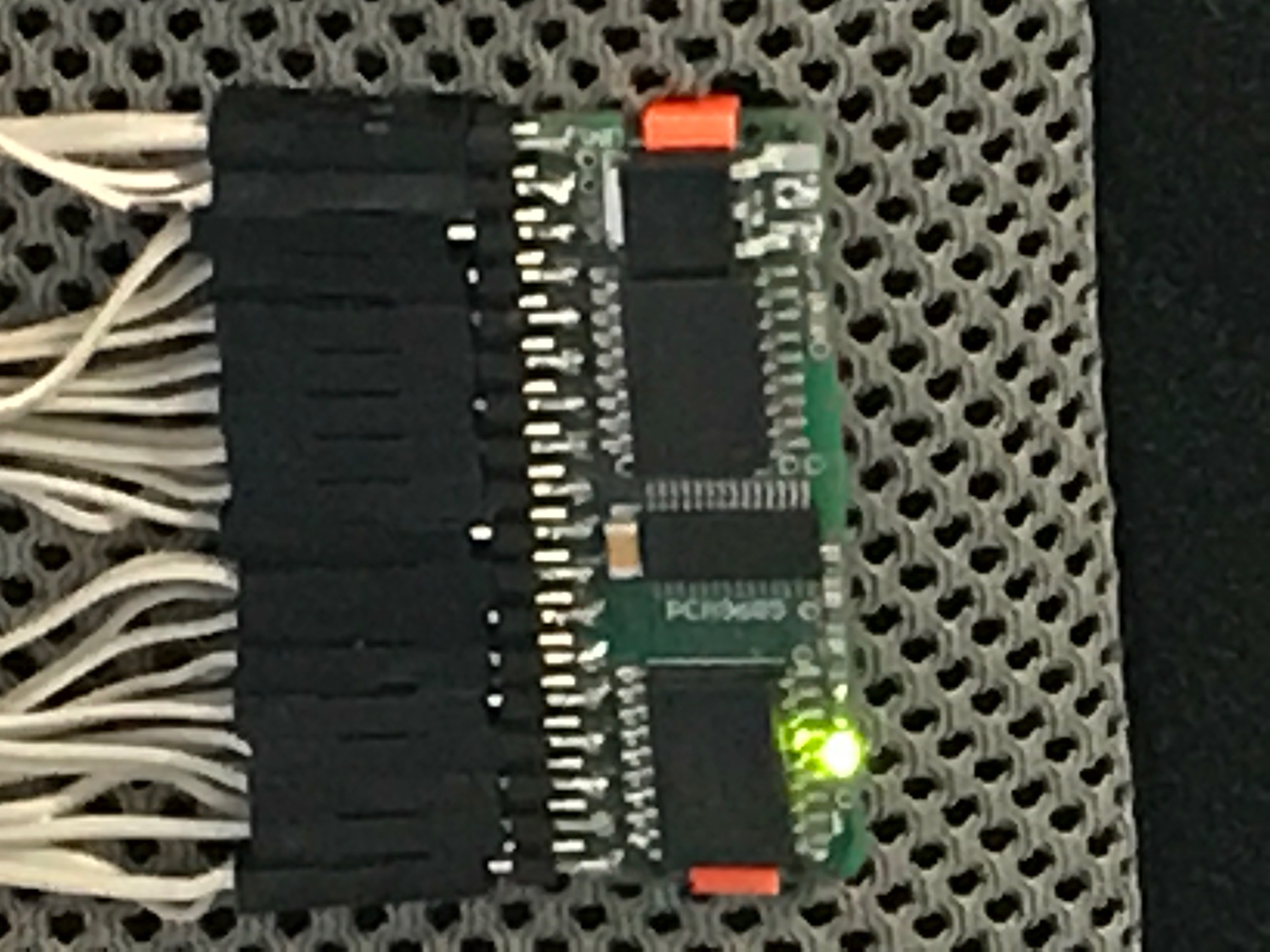
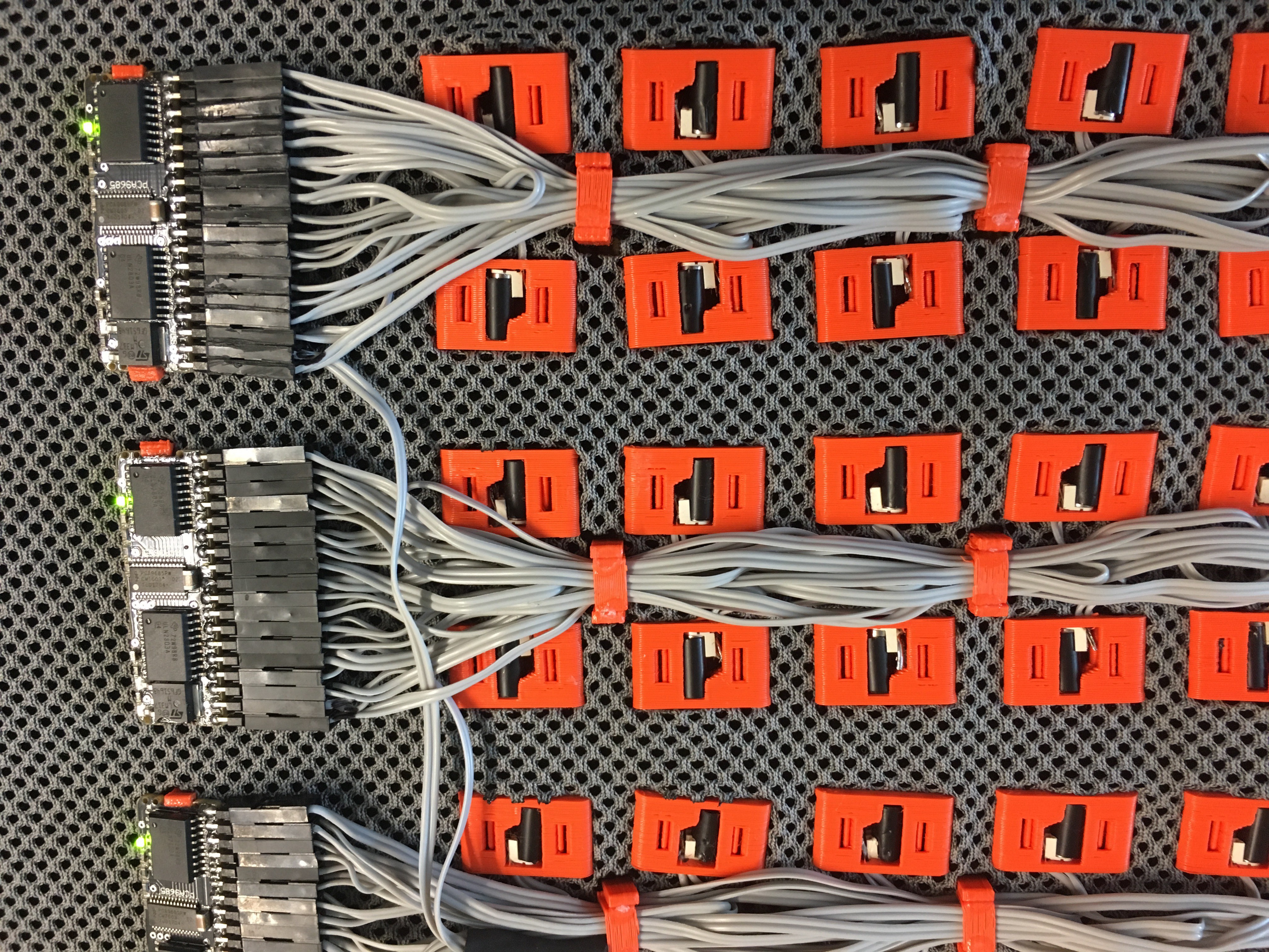
An Up board was used instead of the Pi for camera processing, just because it was the system recommended for the Realssense camera (intel robotics kit). Data is then send by I2C to eight custom-made PWM expander boards (based on the Adafruit Servo expander boards), but including both a PCA9685 and the necessary driver for the motors. Each board further includes a voltage regulator, allowing the system to be fed by a normal 5V power bank.
For easier rebuild, all encapsulations are made by a standard FDM 3D printer, and wiring with normal flat wire and crimp contacts / pin header on the driver board (could be also replaced by just soldering).
Motors (and driver boards as well as cable routing) are held in place with the 3D printed clip form in corresponding holes in the textile for a clean setup.
Since weight is evenly distributed the only heavy component remains the power bank, and instead of a belt system we used allow multiple persons to test the system on faires with quick changes, one could normaly just use a tight textile, make the holes into and mount the electronic.

 SunFounder
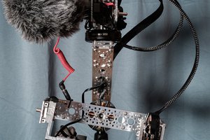
 Matt Barr
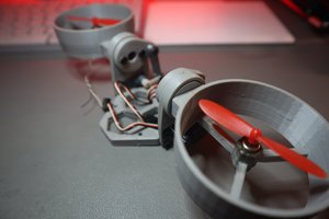
 Saul
Saul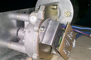
 Alastair Young
Correct and corrected - and that was embarassing because i got your name right beforehand, e.g. citing you in the text in the upcoming ISWC2107 design exhibition (http://iswc.net/iswc17/program/designexhibition.html), only excuse might be it was a last minute write down. Sorry for that. We are aware that the resultion is a bit to good - on one hand we argue with fault tolerance if some motors break down, more importand we want to test the belly threshold on the long run (to test if we can get something like learning effects to distinguish a slightly better resolution). But most importand thing to now is improving the sensor system.