 jean.perardel
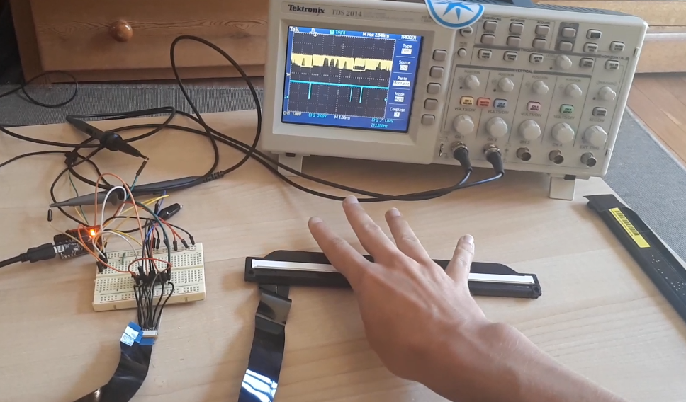
This solution implies the use of light triangulation to read a very precise coordinate. Basically, it's like having a huge number of IR receptors with some IR LED. You turn on every LED one by one and read the sensors. When one receptor can't see any light, it means that an object is blocking the light. With enough LED and sensors you can get a much more precise solution.
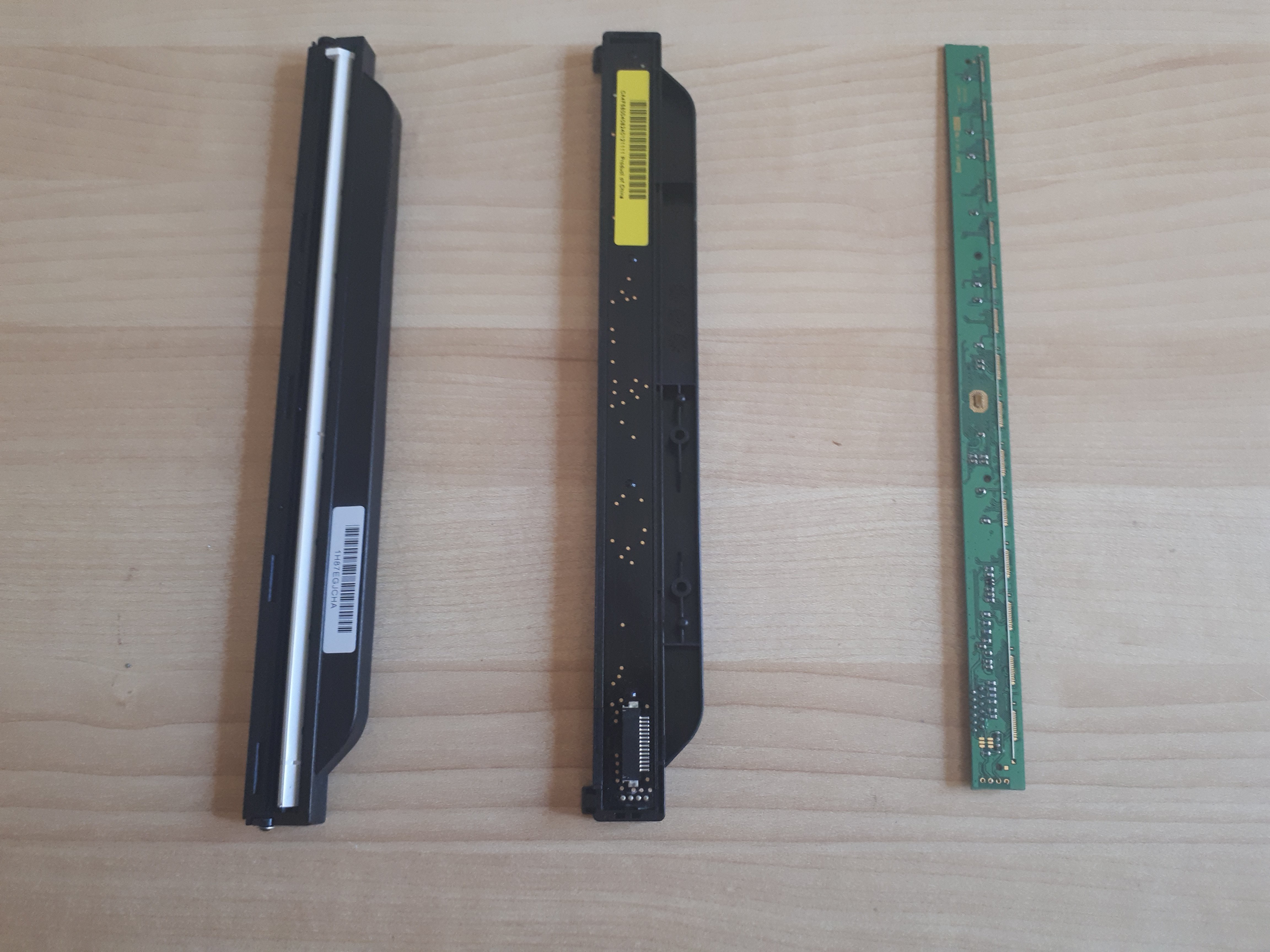
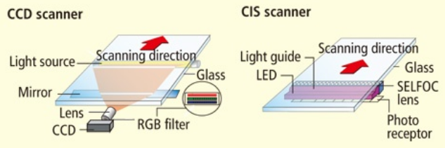
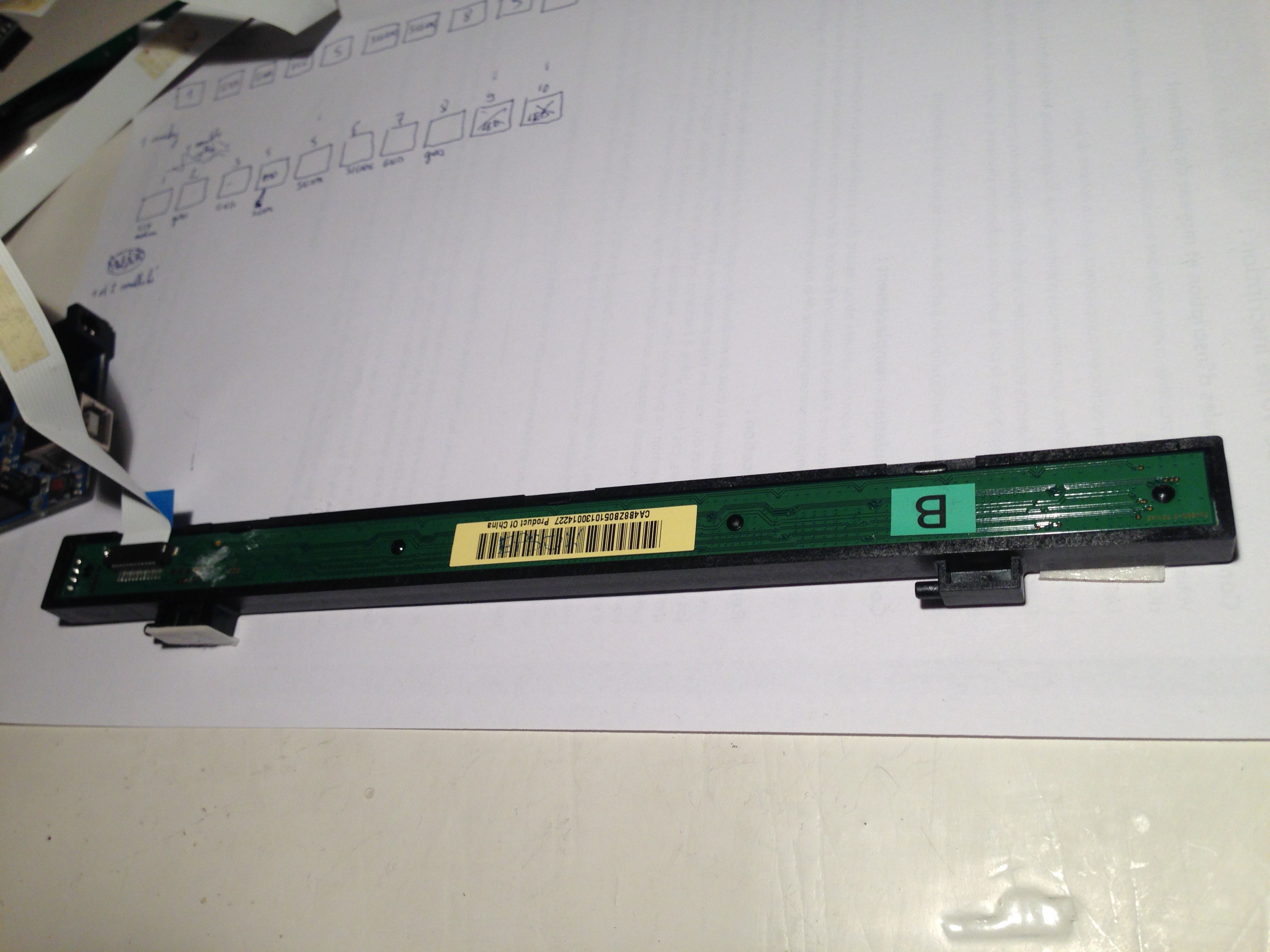
But for this project, I was looking for something more suited for the reading. A CIS sensor, is in most scanner. In those devices, it's basically a black and white camera which reads only one line of pixels. To scan a color document, a RGB LED blink in the three colors and the CIS reads all of them for every line of the document. Then it can calculate the exact colors depending of the Red Green and Blue reaction.
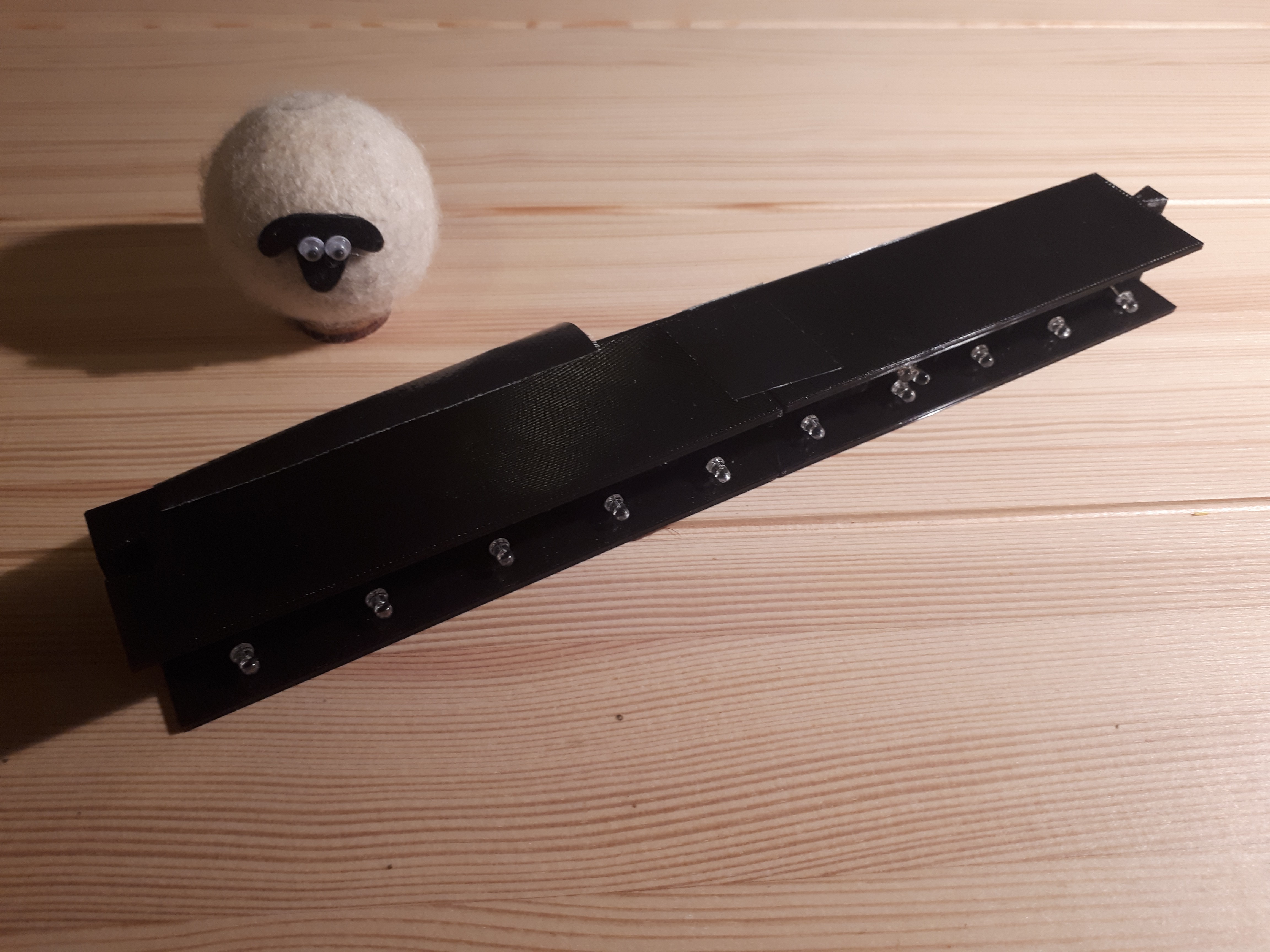
Using a CIS sensor gives you access to 2700 light sensors on a 20cm line. Most people who take sensors and actuators from an old printer/scanners only take the RGB LED and the light conductor from this part, as we can see here. If you like recycling, you could examine the possibilities of CIS. Not having found many DIY projects on the internet using them, there are probably a lot of different ways with which you could use these sensors! In this tutorial I will also explain how to hack your own scanner.
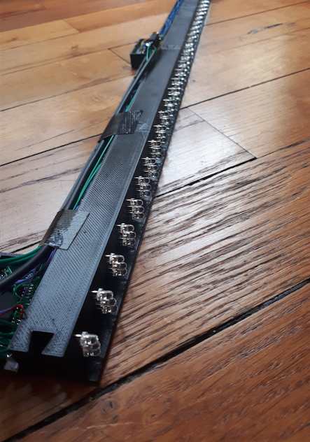
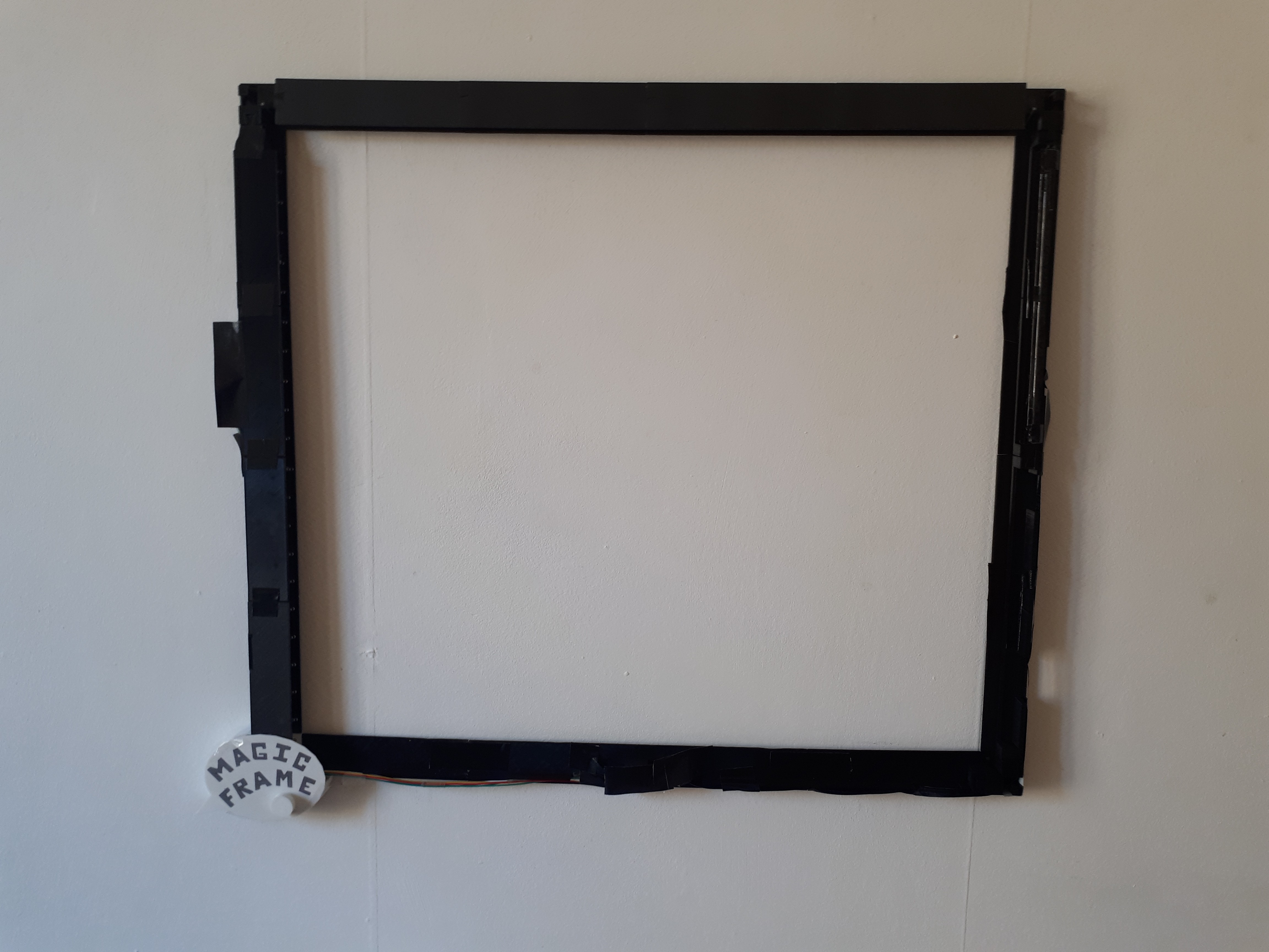
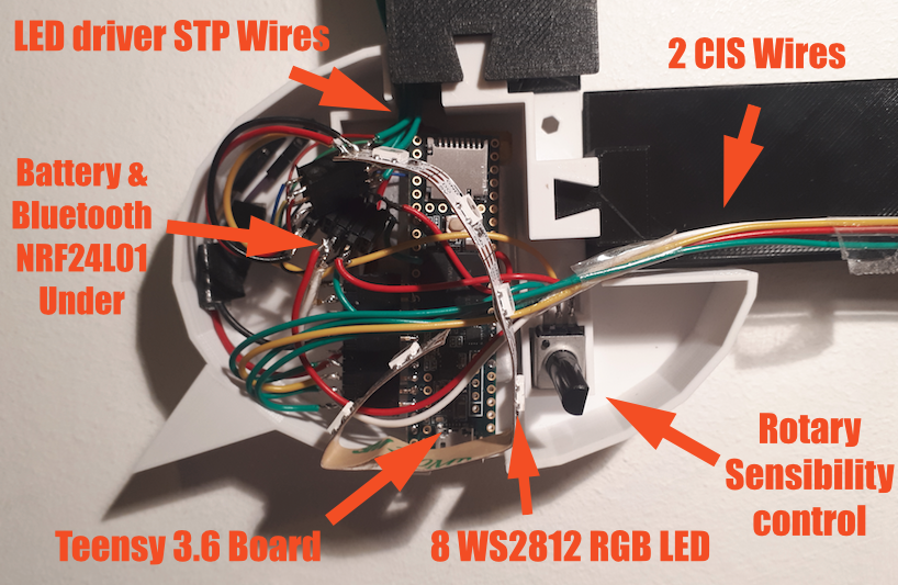
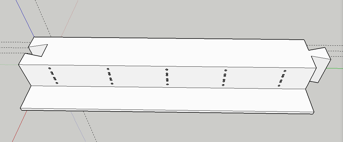
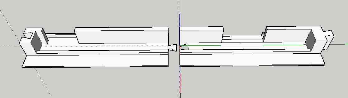
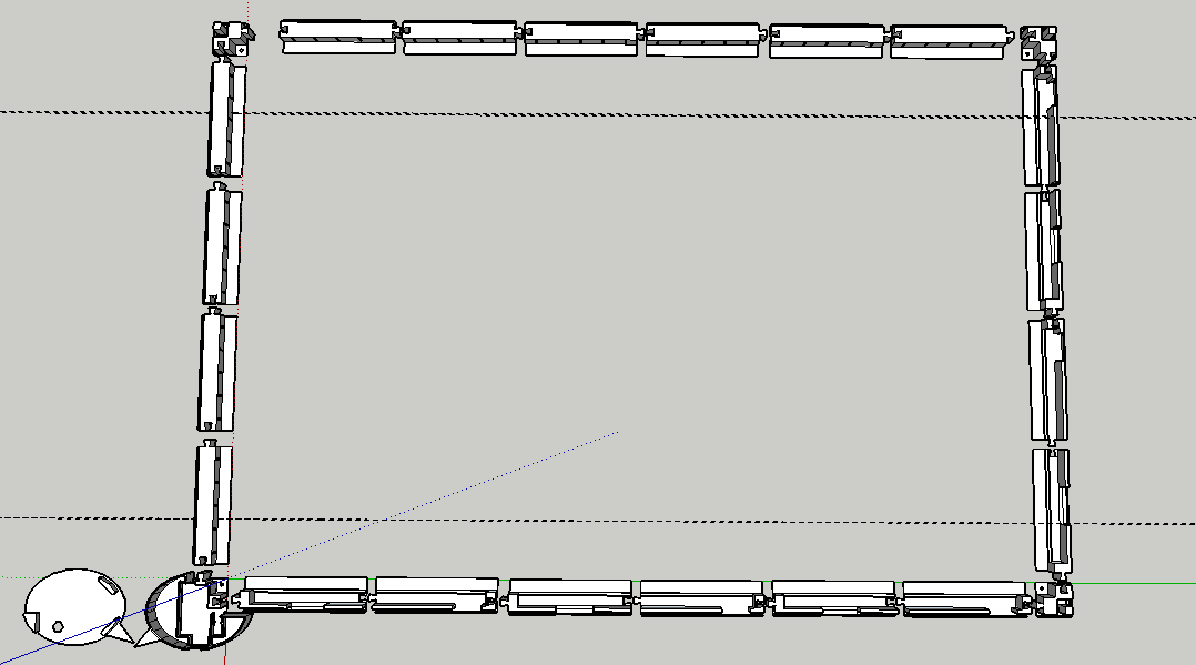
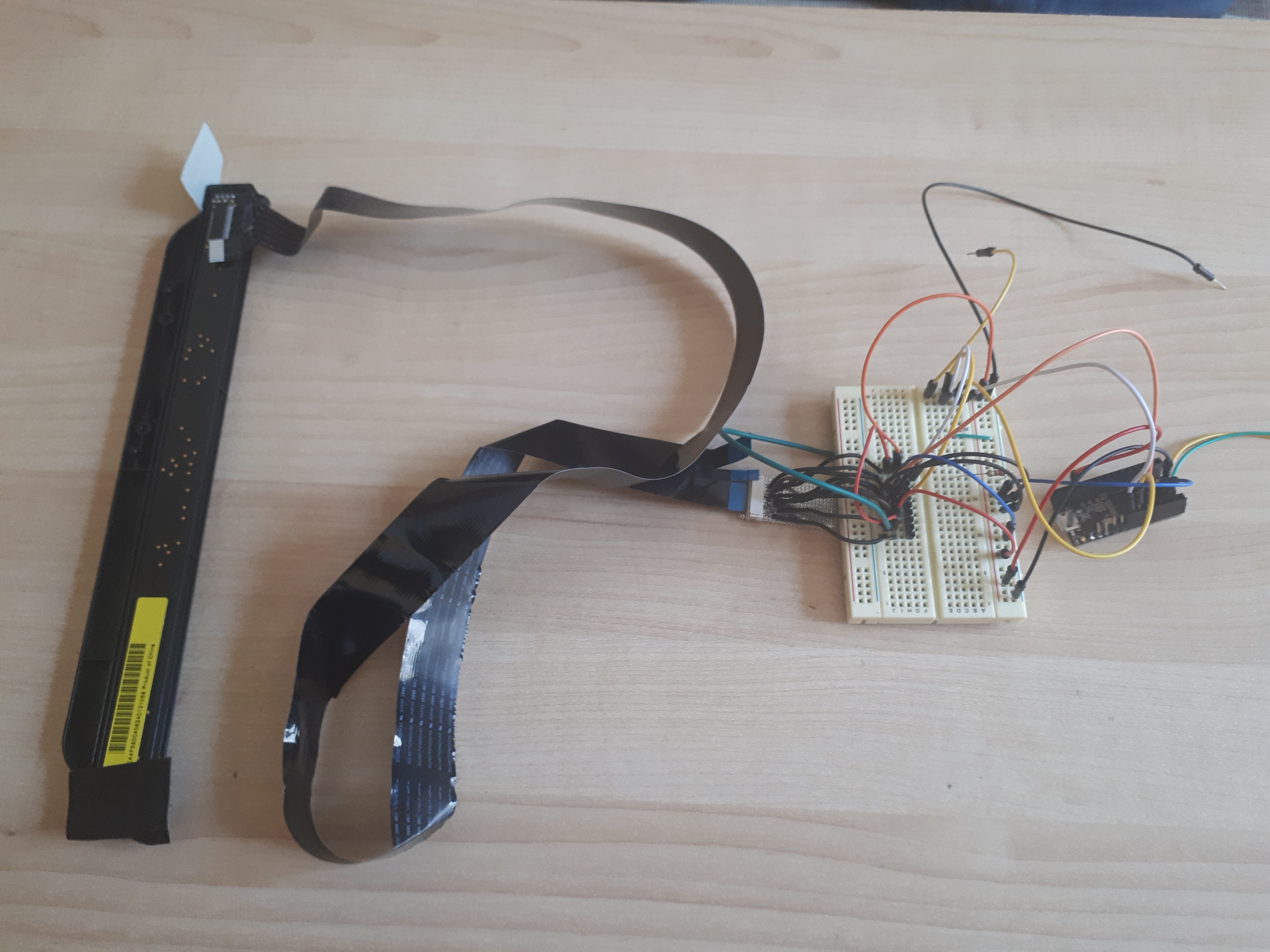
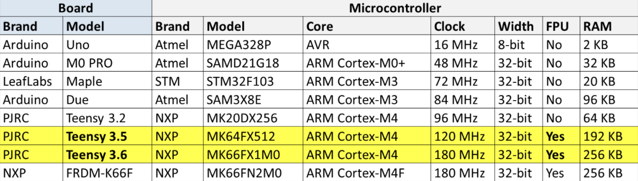
For this touch table, I used one CIS sensor with 24 IR LEDs. The object is detected on a 740x380mm surface by a Teensy board (which works under Arduino environnement). This board turns the IR LED ON, reads the CIS and calculates the exact position of an object. Then it sends the coordinates as a mouse, a keyboard, a Python program or just as Serial on a Raspberry Pi which shows the interface through the HDMI on a 32" TV screen.
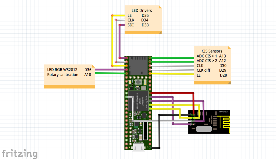
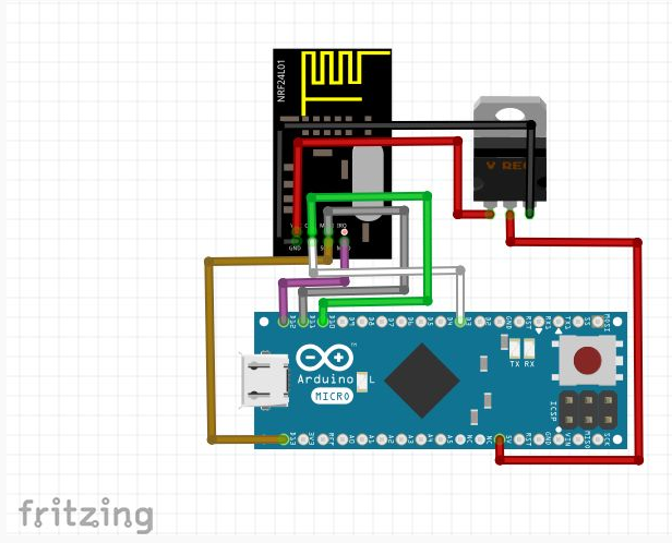
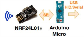 The particularity of the Atmega32u4 on the Arduino Micro board is to be able to act as an USB HID device and/or a serial port. This mean we can send some Keyboard keys, mouse position or CDC serial data.
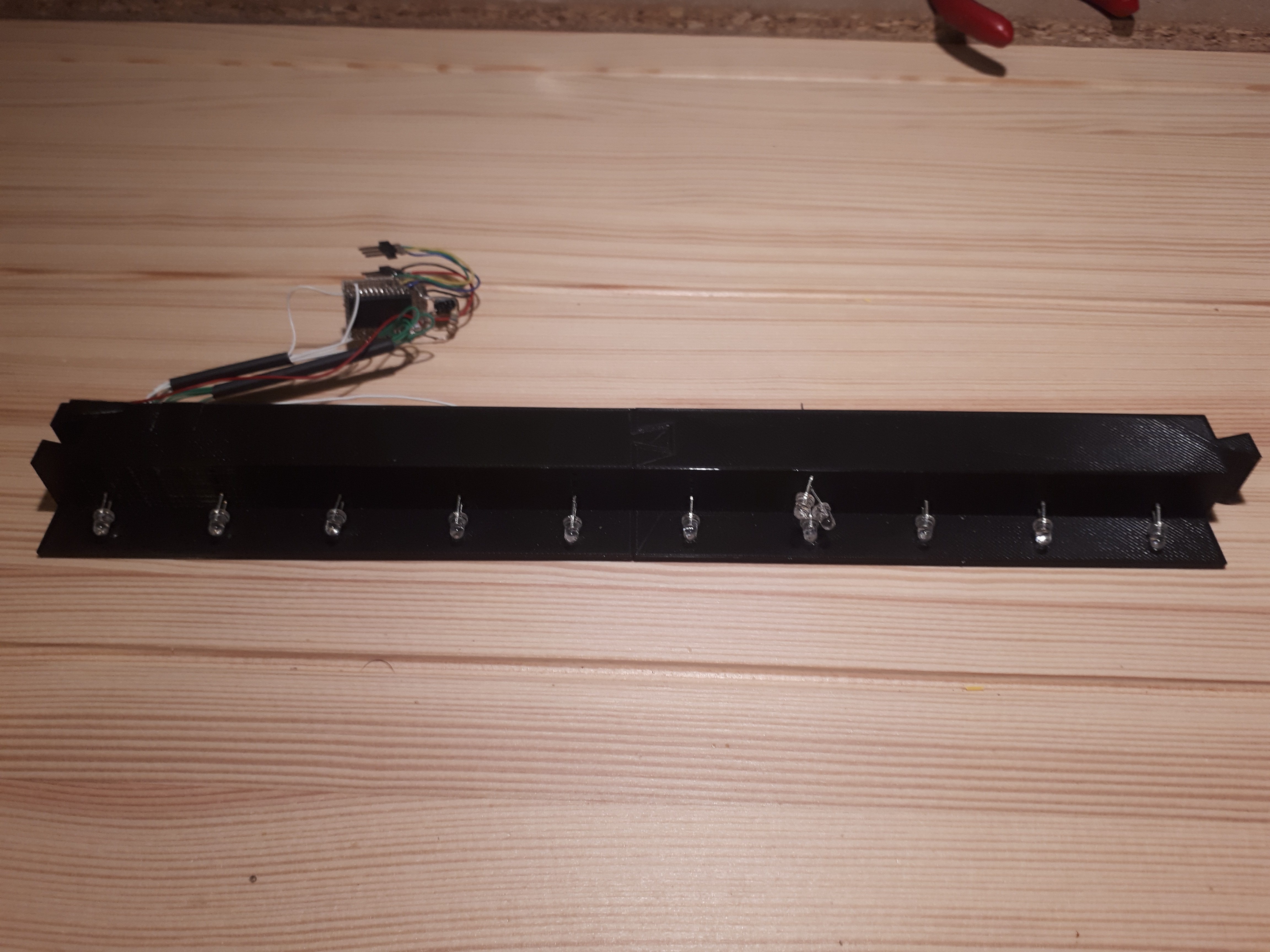


 Alpha Charlie
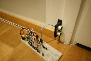
 Timo Hyvönen
 hackaday
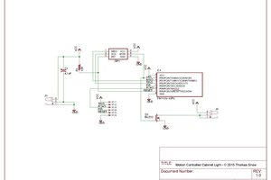
 Thomas Snow
hey I am using your diy project, for a personal use, well i just couldn't understand the assembling of the frame. the use of the pexiglass, and specially the mirror. I was hoping if you could help me out a bit