 jason.gullickson
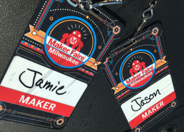
Jamie has a long history of fund raising and is always looking for innovative ways to help raise money for worthwhile causes. She's also a fan of vintage arcade games (as am I) so when she came across something that combines both we knew it was something we wanted to see more of.
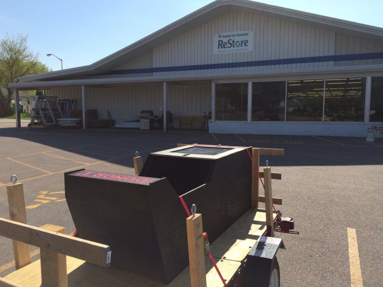
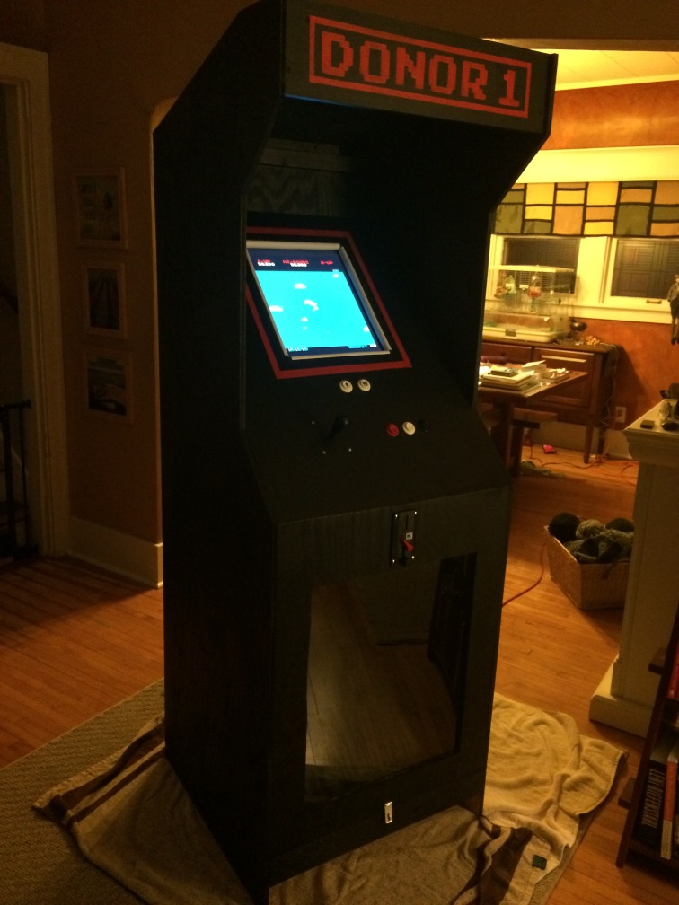
The "charity arcade machine" turns an otherwise unproductive (but fun!) behavior into something beneficial. DONOR-1 is the first in a series of machines we're designing and our goal is to produce reference documentation and instructional materials (all open-source of course!) so others can build similar machines and help make the world a better place one quarter at a time.
Fundraising can be a time and resource-intensive process and in many cases the resources that go into putting on a fundraiser can exceed the funds raised. DONOR-1 provides a very low-overhead way to raise funds for charity that not only improves the chances of a successful campaign, but also taps into an patron audience who might otherwise not get involved in traditional fundraising efforts.


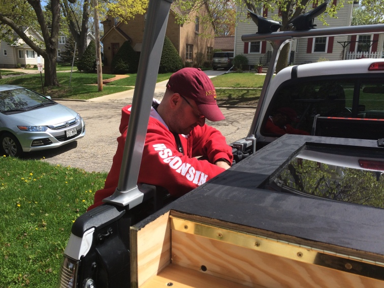


 Dad with the full-size mock-up (the perspective makes it look a bit smaller than in person)
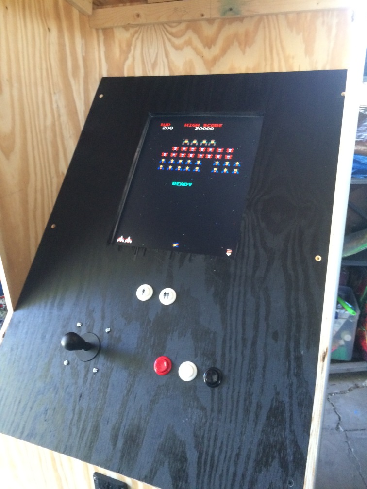
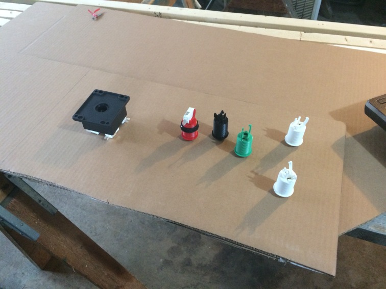 Partial cardboard mock-up of the control panel
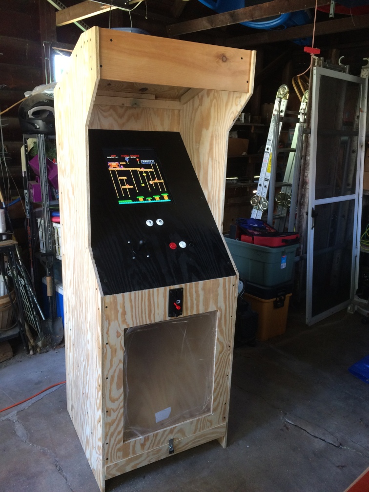
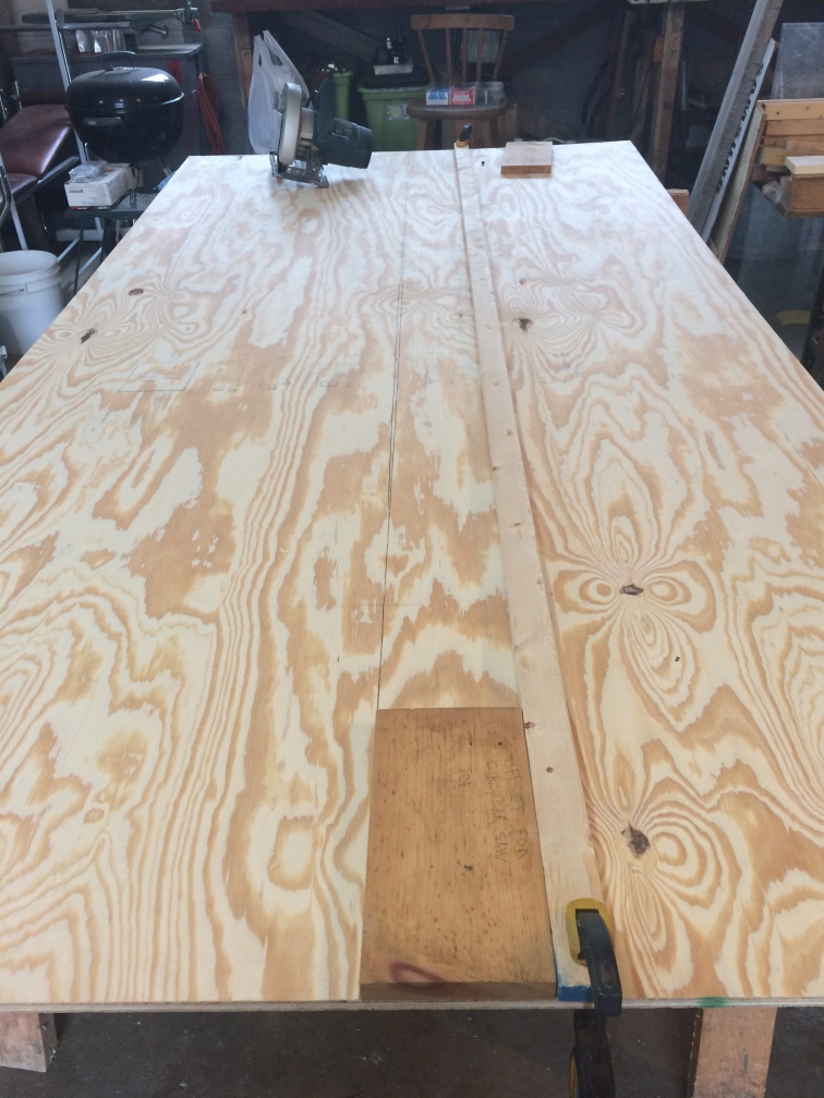 The “uncarved block”…


 zittware
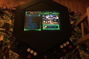

 Ari
Ari