• Programming PIC32 with arduino

    jaromir.sukuba06/16/2018 at 10:53 6 comments

    This isn't probably the most exciting post in here, but since I'm author of firmware for #Badge for Hackaday Conference 2018 in Belgrade , I'm often asked how to update firmware in the badge, so I decided to write it down to single place to have reference point.

    Omitting the most obvious ways (buying PicKit3 or PicKit4 and using MPLABX IDE or IPE tool for this task), there are other ways how to achieve the goal - from the two I have on my mind, both revolving around great piece of software, called pic32prog. You can buy PicKit2 "clone" (PicKit2 was open-source design made and released by Microchip, so those clones are more like derivative works) and use it with pic32prog, or alternatively you can build bitbanged loader using arduino. I used cheap atmega328 nano board from usual vendors, costing me something like 2USD.

    Hook 3,3kOhm pull-up to D2 and D3 pins, then connect

    D4 - 1kOhm resistor - MCLR

    D3 - 1kOhm resistor - B0

    D2 - 1kOhm resistor - B1

    GND - GND

    as you can see on picture

    Clone git or download zip from github, extract and if you don't want to compile it, look for precompiled binary for your OS.

    Now turn the arduino into PIC32 programmer by running

    pic32prog -d:ascii:SERIAL -b3

    where SERIAL is your serial port. For windows it's COMx, for linux it's /dev/ttyUSBx. This should load firmware into the arduino.

    From this point on, this setup should be able to flash new firmware into badge, or any supported PIC32. Run pic32prog -d:ascii:/SERIAL file.hex

    pic32prog -d:ascii:SERIAL file.hex

    pic32prog should find the programmer and if wired properly, also the target. Don't forget to have fresh batteries installed in badge.

    The rest should look like this

    Notice the full FLASH loading is really slow - that's what you pay for trivial programmer from parts you have in your drawer - but acceptable for occasional firmware update.

  • Exploring Microchip XC16 compiler

    jaromir.sukuba01/09/2018 at 10:44 10 comments

    As I was playing with my LLG project, I spent a few moments with exploring XC16 compiler.

    Three facts are known about this one

    • It's based on GCC
    • The free version is told to support only -O0 and -O1 optimization levels
    • Full version (higher than -O1 optimizations) costs a lot of money

    Honestly, I'm OK with all three points for hobby projects, though I try to use 8- or 32-bitters, where open source compilers are available. Less known fact is that source codes of XC16 are available and free to download, probably mostly to satisfy GNU license requirements. Better than -O1 compiler options are fine for squeezing last bits of optimization efforts, though - that's why the paid version exists. Though the sources are available, in professional circles not everybody will spent their expensive time building the compiler (that is far from being trivial exercise) with nobody to ask questions, so they buy directly the full version plus support from Microchip...

    ...or something. In fact, I'm able to use optimizations higher than -O1 on free version. Compiler complains I have no valid license, but the code builds and runs just fine, with apparent results of compiler optimization efforts. That's what i did on LLG, where I built the code with -O3 and code execution is indeed faster than with -O1. That is where story could end, but I went further.

    I downloaded soruces for XC16 1.33 from here. The archive contains almost 10.000 files in 5200 directories, so I unziped it on temporary location. In directory \v1.33.src\src\XC_GCC\gcc\gcc\config are all targets, including the ones for XC16 /PIC30/ - because originally the compiler was meant for dsPIC30 DSPs, PIC24 and dsPIC33 being derivatives of dsPIC30) - as well as PIC32 /PIC32/.

    in PIC30 directory there are files pic30.opt and pic30.c being of interest. At line 3707 of file pic30.c, there is block of code

    #elif defined(LICENSE_MANAGER_XCLM)
      if (pic30_license_valid < MCHP_XCLM_VALID_PRO_LICENSE) {
        invalid = (char*) "restricted";
        if (pic30_license_valid < MCHP_XCLM_VALID_STANDARD_LICENSE) {
          nullify_O2 = 1;
        }
        nullify_Os = 1;
        nullify_O3 = 1;
      }
    #endif
    
        #define NULLIFY(X) \
        if ((X) && (message_displayed++ == 0)) \
          fnotice(stderr,"Options have been disabled due to %s license\n" \
                  "Visit http://www.microchip.com/ to purchase a new key.\n", \
                  invalid); \ 

    The variable 'pic30_license_valid' is being set on results of xclm, license checker. So this is where optimizations warning are being emitted. Never mind, lets look further.

    #ifdef LICENSE_MANAGER_XCLM
      if (mchp_mafrlcsj) {
        pic30_license_valid = MCHP_XCLM_VALID_PRO_LICENSE;
      } else if (mchp_skip_license_check) {
        pic30_license_valid = -1;
      } else {
        pic30_license_valid = get_license();
      }

     By setting proper value into 'mchp_mafrlcsj' we can omit the license check. The option is entered via command line entry, being described in pic30.opt file, line 228:

    mafrlcsj
    Target RejectNegative Var(mchp_mafrlcsj) Undocumented
    

    So, entering -mafrlcsj option into command line should be equal to having proper license. When compiling from command line using make or similar tool, it should be straightforward, within MPLABX IDE it works like this:

    I created file cmd.txt containing single line

    *cc1:+ -mafrlcsj

    and in project settings I opted to use this file

    and hit compile

    Notice the resulting binary is indeed a bit smaller, though at -O1 optimization (as if the optimization beyond -01 would be prohibited) is the binary even bigger - not sure about this one.

    I took my LLG sources and performed tests on them (code size and execution time of geolocation algorithm), using all levels of optimizations with and without additional options as desribed here.

    It's apparent that with options the compiler tries a bit harder. At Os (where code size is main factor) it gets 20B lower, at O3 (where speed is at premium, code size is secondary) it indeed runs a bit faster.

    So, what is described here is option to get full optimization level of XC16 compiler without need to recompile...

    Read more »

  • Infineon - scary movie, part one.

    jaromir.sukuba11/22/2017 at 08:31 1 comment

    Offering from Infineon piqued my interest lately, as the price for Cortex M0 with 32k FLASH and 16k RAM in small package for under 1EUR from EU stores isn't bad. I bought one XMC1301T016F0032ABXUMA1 (oh my) and tiny devboard XMC2Go and Infineon is kind enough to provide some design resources. +1 point from me.
    They also provide IDE named DAVE based on Eclipse and GCC, though being only offered for Windows. Meh, I don't mind it much, as I'm going to switch to native Linux tools as soon as possible, vendor IDE is usually good enough to get basic grasp and move on to something useful later. But anyway, I would be happier if they provided also non-windows variant of the tool. It's late 2017, dominance of "Wintel" is not as strong as used to be.

    So, IDE installed, let's run it and create new project. Nope.

    Clicking to Next, but nothing happens. It just froze here. So again, Cancel, new project, Next... Next, Next, Next, Next, Next, Next, NEXT NEEEEXT... Screw you. Closing IDE, trying the same... no avail. No error messages, just non-responsive program. Restarting windows (because that's what always helps), then running IDE, the same result. I just can't start a project on freshly installed IDE.

    Googling time... it reveals I'm not the only one with this issue. So, after I install the complete dedicated IDE from Infineon solely for Infineon MCUs, I need to install some more libraries for this dedicated Infineon IDE to actually support the Infineon MCUs. Go figure.

    Since I don't want to spend any more time restarting everything and figuring out what everything is needed, I just install everything available. After one or two restarts of the IDE and half an hour spent dicking around I'm finally able to start a empty project. Hallelujah, I thought - at the time I didn't know the worst is still to come.

    Hey Infineon, why on Earth the IDE dedicated to Infineon MCUs isn't able handling of Infineon MCUs? Why the plugins or whatever can't be installed from main install?

    With the XMC2Go kit in USB port (being enumerated as J-Link debugger) I built the empty project and flashed the FLASH of target MCU on kit, everything went smoothly, so I considered this as done. But devkits are always just training wheels and you don't own the MCU unless you can buy virgin part, stick it to PCB and blink a LED with it. I took out my XMC1301T016F0032ABXUMA1 (once you start diving into ARM world you notice the weird part numbers), soldered it onto one of my breakout boards and tested it for continuity and shorts. 

    For flashing the board, I elected for J-link EDU I had on hand, just to connect it. Pins 5 and 6 are GND/Vss, now I need SWD pins. And they are not listed in datasheet. Hey Infineon, you always list such as important pins in datasheet, no matter what. Datasheet is go-to resource, the first document one takes look at. I opened reference manual, being mere 1337 words long (oh 1337!) and sine nobody in his/her right mind would start reading it page by page I hit SWDCLK into full-text search. Notice how easy and fast I progressed here, since I knew what to search for, beginner would spend hours looking for what to look for.

    I found the SWD pins are shared with other pins

    depending on boot mode, but SWD are top ones, so probably are the default for given pins, what would be logical choice, as every other manufacturer has programming/debugging pins enabled by default. Isn't it logical? Yes it is. Is this the case of Infineon MCUs? No, it isn't. So I connected SWDCLK pin of J-link EDU to P0.15 and SWDIO to P0.14, asked J-link software (DAVE was off at the time) to find the target on SWD interface and... it didn't found anything (<insert Spaceballs reference here>). Never mind, check connections, try again, reboot, reinstall drivers, reinstall software, try in DAVE, install Keil uVision, reboot few more times, take out SMT32 Discovery, google, install J-link firmware on it, try...

    Read more »

  • STM8S001J3 - The Good, the Bad and the Ugly

    jaromir.sukuba09/12/2017 at 07:54 12 comments

    Before the STM8S001J3 MCUs hit the streets, I received a few samples directly from ST Microeletronics to evaluate. ST finally jumped on a train ran by companies like Microchip or NXP for something like 20 years. It is coming from STM8S family, now being almost classic and well proven chip family.

    The Good
    STM8S001J3 is very similar to STM8S003F3 - so much similar it's probably the same silicon chip, actually. There is nothing inherently wrong about it, as it makes development cheaper - that is easier for manufacturer and cheaper for end customer - and allows to jump on existing development tools, again enabling customers to work with the MCUs easier and faster.

    The Bad
    On the other hand, dark side if this decision is easily recognizable. Fitting 20-pin chip into 8-pin frame forces designers into some compromises - which pins to expose, which ones to leave unconnected? Another option is to merge multiple bonding pads to single package pin - and that is route which was chosen in ST.
    It allows multiple peripherals to be shared on single pin, which could be advantageous at times, also uncomfortable, as seen later.
    From 8 pins of SOIC package, two are for power supply pins - there is not way doing it otherwise. One is sacrificed for VCap pin. As this one is based on STM8S, with supply voltage range up to 5V and relatively modern core manufactured on "dense" manufacturing process, innards of MCU are supplied by lower voltage, requiring internal LDO to do this job. VCap is pin to connect capacitor to keep this LDO stable - and this pin can't be used for anything else.
    I wish ST would design also STM8L device in SOIC package. Apart from Vdd being maximum 3,6V (nothing unusual in last 10-15 years), this would free up one pin (now sacrificed to VCap) and sleep current consumption would be as low as usual for STM8L devices. STM8S (including STM8S001J3) do have sleep consumption of about 5-10uA, what is one order of magnitude higher than sleep current of MCU devices designed 15 years ago!

    The Ugly
    Now, with 5 pins, guys at ST had to decide what to do with the other ones. Higher pin count STM micros do have dedicated NRST (Not ReSeT - low active reset) pin, but from obvious reasons they decided to omit it on 8-pin STM8. And SWIM pin is shared with three other pins; being it not exactly ideal solution, as confirmed by datasheet too:

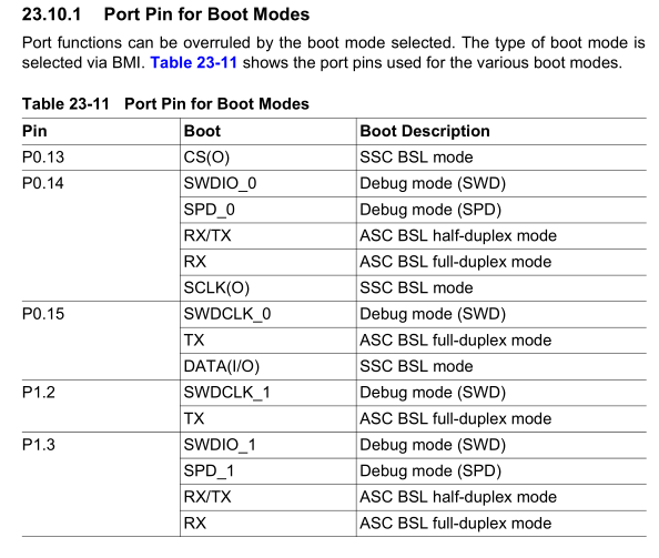
    So, setup your data direction register into wrong state and there you have it - OTP device. We have seen really bad programming interfaces in the past - just like AVR. With more than one way of programming of FLASH, you can easily lock one or another access, having fall-back in 1980's parallel programming. That being said, once the fuses were setup correctly, one didn't have to touch it anymore and any further access was safe. On this device it's different. DDR registers have zero protection agains fuck-ups, from programmer side or even from runaway program - that is particularly dangerous, IMO. With STM8S001J3 you should always have a few spares and hot-air soldering gun for the case you do something goofy in your program. One solution of how to escape this problem is to set-up and use some kind of bootloader to load the FLASH.
    While absolutely vital SWIM pin is shared with three other pins, PB4 is just alone. I wish it would be other way around. And alternative pin functions list don't mention MISO signal of SPI interface. Either MISO is forgotten in documentation, or it's forgotten to be bonded out. On STM8S003F3, MISO is on PC7, which is explicitly being listed as NC

    I hope it's alternative function to some other pin, otherwise the SPI would be seriously crippled without MISO.

    Resumé
    All in all, while STM8 family seems to be one of the better 8-bit MCU design, this 8-pin variant does seem to suffer a bit from compromises during design stage. I really hope ST will release new 8-pin device, as there seems to be space for further optimizations.