 Yann Guidon / YGDES
The logic strategy has evolved since 61. Making Y8 more energy-efficient with a deglitcher and the first code for the ALU is not yet satisfying, so instead of digging that part even more, let's shift our attention to the register set... A clean, fresh reboot of an old subject could work :-D
Let's start with a reminder about the structure of the registers: there are 8 bytes with 2 read ports and 1 write port and the write port shares the address with one read port (further saving instruction bits, but not control logic). For now we focus on the decode logic of the read ports, which we then duplicate to get the SND and SRI fields.
The register set is heterogeneous and uses multiplexers organised as a "balanced control balanced binary tree", seen in the picture below:
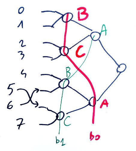
Address bits b0 and b1 are swapped at the middle of the tree to even/balance the load but control gating reduces this constraint (we still use this method because the fanout constraint is not eliminated). Bit #2 at the to of the tree is not affected.
One bitslice uses two of these fancy "MUX8" to read the two operands: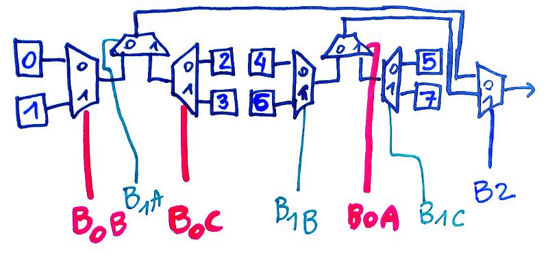
Registers 5 and 6 are swapped, this is the only difference to remember. The address bits work almost like a normal MUX8, with the fanout slightly enhanced.
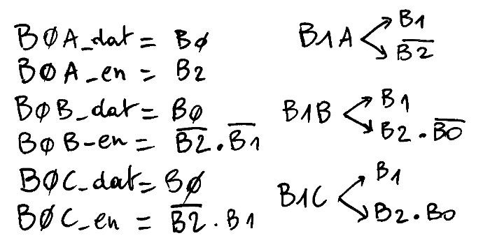
We are now interested by the enable logic : only 3 of the address bits need to be changed, out of 7, and only if needed. For example there is no reason to change B1B when B2=0.
So far, so good...
The register set is probably the most critical thing to decode As Soon As Possible so these simple equations are very convenient. But this is not the end of the story because another class of data can further inhibit the addresses:
- Some instructions (INV, IN, OUT) don't use the SRI field
- Other instructions (INV, IN) don't use the SND field
- The SRI field is not used in IMM8 or IMM4 form
The last one seems very easy to solve : bits #11 (R/Imm8 flag) and #10 (R/Imm4 flag) must be 0 to select SRI, so the Enable for the whole MUX8 must also AND with not ( Instruction(11) or Instruction(10) ). However this first approximation disables the 6 opcodes that don't use Imm8 (in particular the 3 opcodes that set bit 11: SA, RC, LDCH) and doesn't disable IN, OUT and INV (though only OUT sets bit 11).
However...
- IN, OUT and INV are not expected to be executed frequently enough to save significant power if control-gated. The few extra decoding gates do not a big deal but they add precious latency in the critical datapath.
- OTOH it is critical to correctly decode the instructions that don't use the Imm8 field. The bit #11 must be disabled when the opcode is after CALL or (conversely) enabled up to CALL. The last option is the easiest to code, with a 3-inputs gate : not(b15) or (not(b14) and not(b13))
SND is not used for the SET, CALL, LDCL, LDCH, IN and INV instructions. SET is likely the most used opcode so its gating might benefit the system. It is easily grouped with the neighbour CALL instruction with a 3-input gate (b15 & /b14 & /b13) :
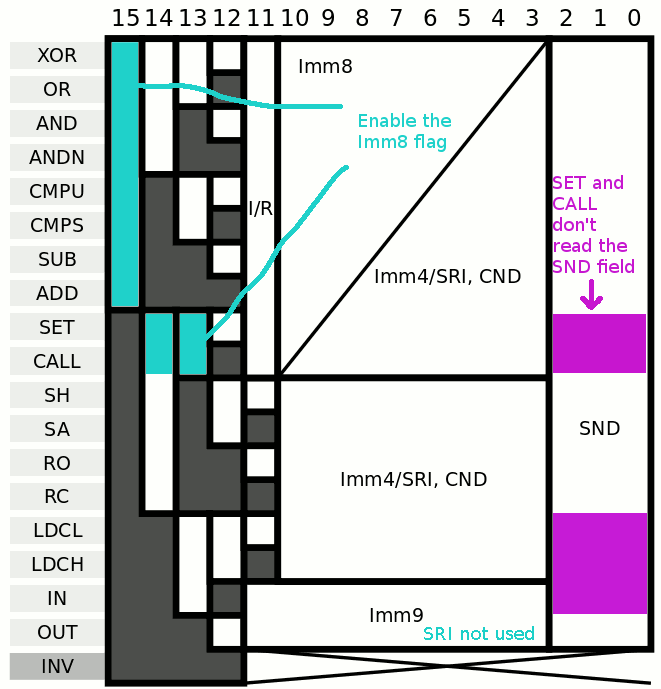
LDCL, LDCH and IN can be easily added (b15 & b14 & /b13) and b14 is the only difference so the inhibition of reading SND is simply (b15 & /b13).
.
Discussions
Become a Hackaday.io Member
Create an account to leave a comment. Already have an account? Log In.