 liebman
Current Status:
Version 2 is functional. All code and hardware design details can be found on github here.
V2 Plan:
- Lower power/longer battery life.
- Reduced component count and lower cost.
- Preserve clock position on power loss.
Already have an account? Log in.
To make the experience fit your profile, pick a username and tell us what interests you.
Current Status:
Version 2 is functional. All code and hardware design details can be found on github here.
V2 Plan:
SynchroClock2.1a.pdfv2.1a schematicAdobe Portable Document Format - 22.60 kB - 10/08/2017 at 17:26 |
|
|
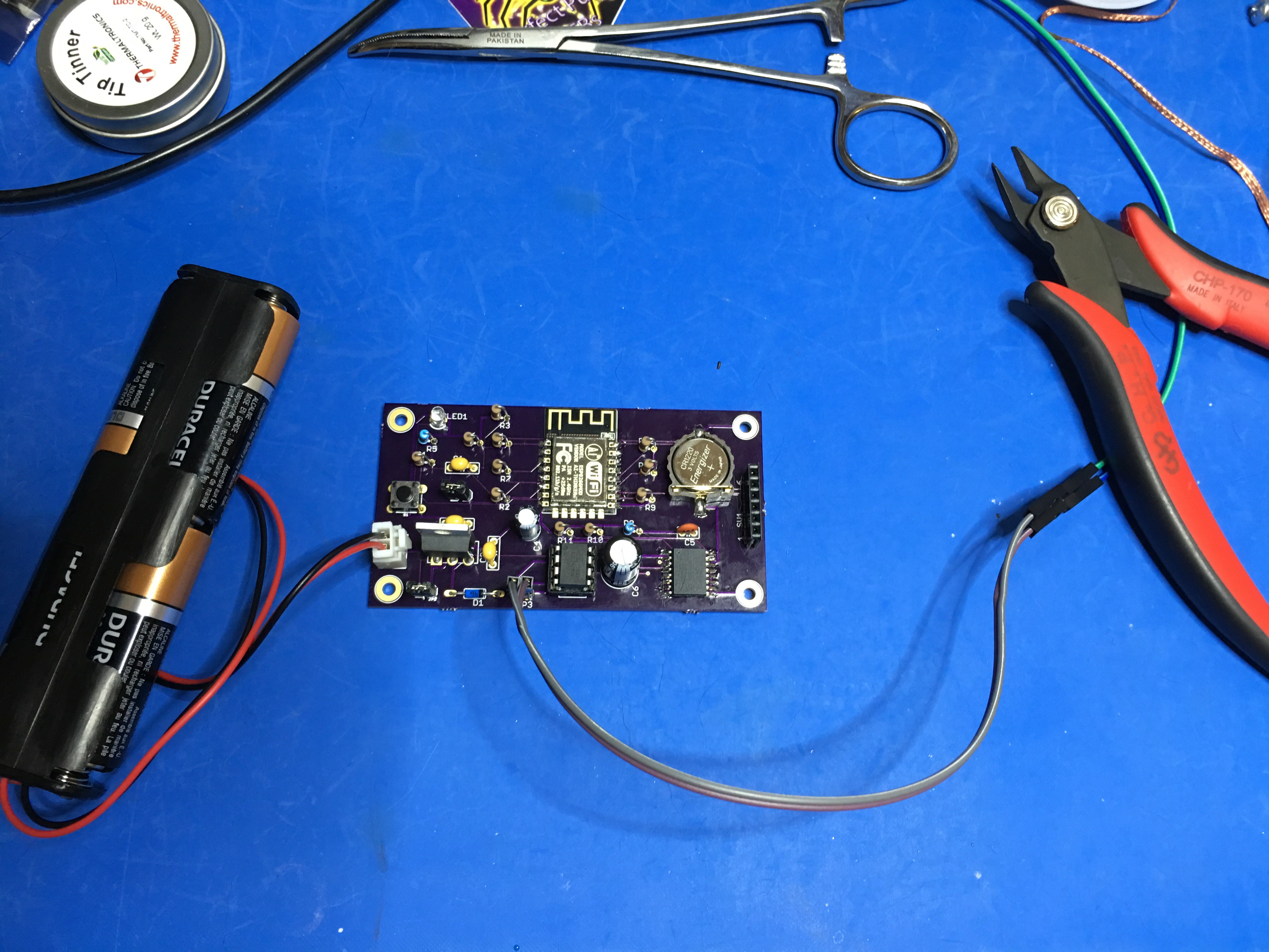
The new boards arrived!!!!
I assembled one and testing shows that the new design is functional!
Next: test power-fail support and measure power usage.
First, I've switched to a MCP1825, I was trying out a MCP1755 but its only rated at 300ma / 350ma peak. The ESP8266 will sometimes draw at this level making the MCP1755 marginal, the MCP1855 supports 500ma.
I've updated the v2 branch on GitHub with the changes and ordered a small set of boards from OSH Park and after I've verified they work I'll merge the v2 branch.
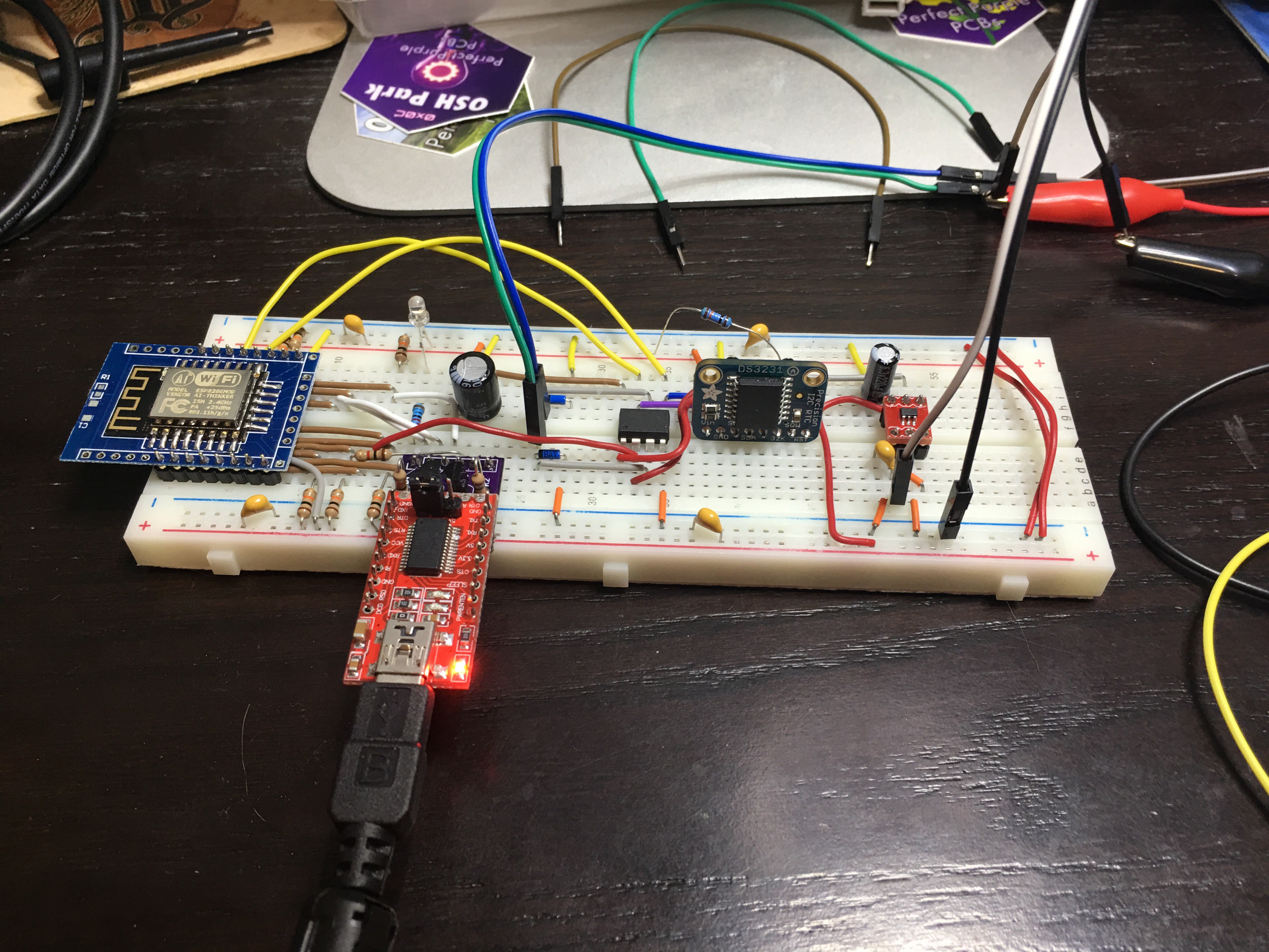
I'm still having issues running this on the solder-less breadboard, I think its just too noisy for ESP8266. We will find out when the new boards arrive.
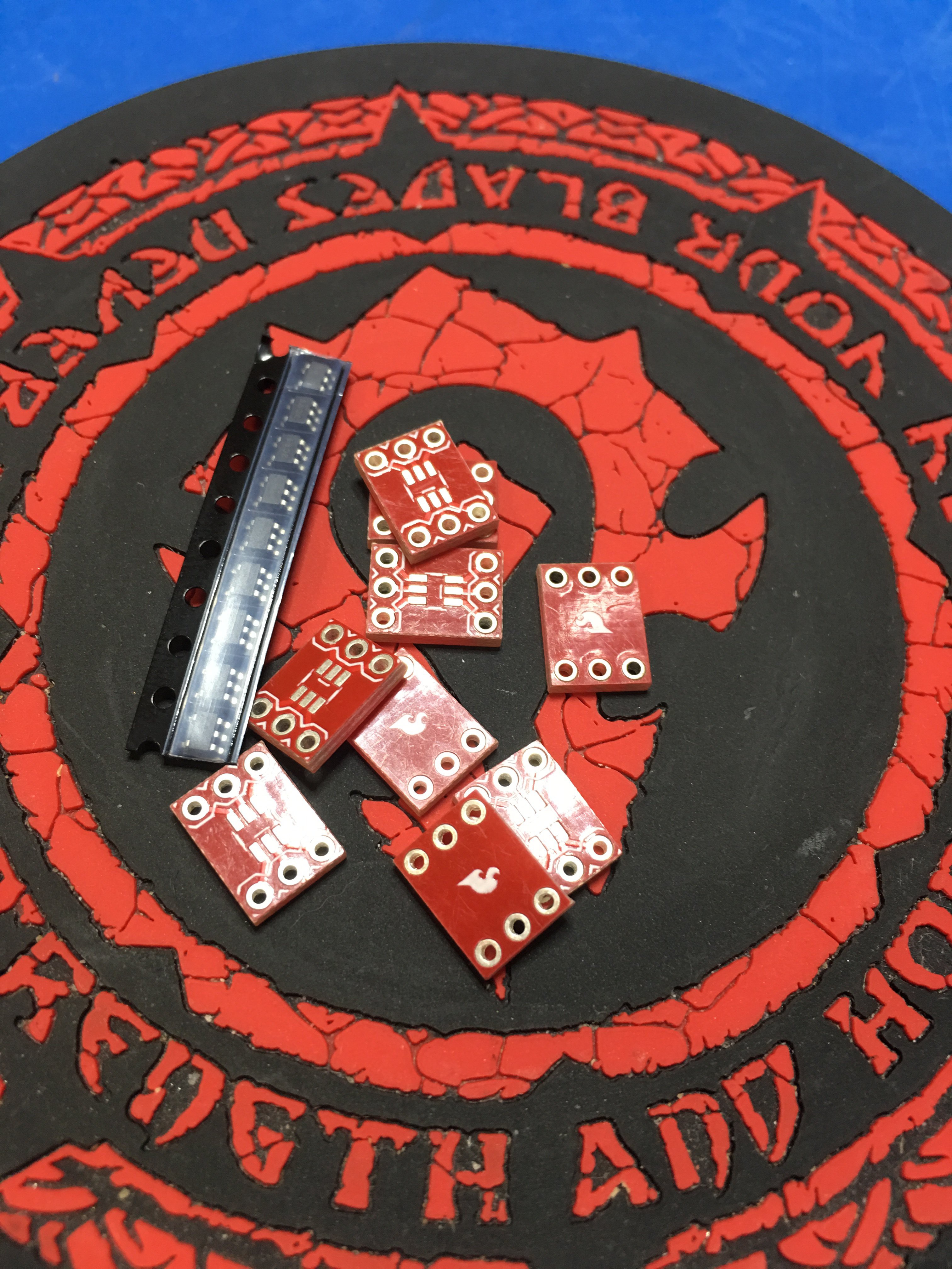
I received my order of MCP1755 voltage regulators Friday and soldered one of those tiny SOT23-5 devices on to an almost equally small breakout board.
I used it to power a breadboard version of the clock controller. Seems to work ok. I had some strange resets on the ESP8266, they are very sensitive to their power being stable, but they seem reduced after increasing the output capacitor.
Power fail testing shows using the power good output from the MCP1755 works much better that using the reset output from the DS3231. Additionally, the 510uf capacitor provides more than enough juice to manage a tick and save the clock position information with room to spare.
I realized that by using the power loss signal from the RTC the voltage may be too low at that time to properly tick the clock. I'm going to try a voltage regulator that includes a power-good output. I've ordered a few MCP1755's and will hopefully get to try them out this weekend. Another benefit is that it will be easier to test the power-fail worst case timing as the regulator has an enable pin as well. With that I can use an Arduino to watch the DS3231 1hz signal that I'm using to tick the clock. When it marks a new second I can disable power which will require the "backup" capacitor to supply power for the entire tick and then for the time to save the position information.
A second benefit is that the backup capacitor can be much smaller! I calculated that a 220uf capacitor would just have enough at the current tick timing I'm using. I plan on using 510uf so give me some wiggle room for various timing that may be required adapting to other quartz clock movements.
Finding the correct size for a power backup capacitor was a bit more involved than I expected. Worst case is that the power is removed just as a clock tick has started. In that case we need to be able to finish the tick and then write the state of the clock to EEPROM with a checksum so we know if its valid or not.
First we have to determine how much current we need. From testing I found that a clicking the clock draws approx. 3ma for the duration of the tick, typically about 32ms. Then it takes 3.4ms per byte written to the EEPROM. We have 8 bytes, 2 for the clock position, and 2 for the clock tick and enable state so thats about 28ms. With the ATtiny85 active running with a 1mhz clock it draws about 0.5ma. So we need to last for a minimum of 65ms drawing an average of 2ma, using slightly rounded values.
Next we need to know the starting and ending voltages required from the capacitor. The Starting voltage is the highest voltage that the DS3231 will use for signaling a power loss, the data sheet says thats 2.45 volts. But we are charging the capacitor thru a schottky diode with a maximum voltage drop of 0.3 volts making our starting voltage 2.15. On the low side we need to know the maximum voltage that the brown out detection on the ATtiny85 will kick in. I have the fuses set to 1.8 volts and the data sheet says that it could kick in as high as 2.0 volts.
Then we can use a handy calculator here, plug in the starting and ending voltages and the current draw, and play with the capacitor value until we get a duration we like. To be conservative I'd like a value that is at least 2 times my computed value.
I've chosen 2200uf as even with a 20% its 1780uf and that will last ~ 133ms.
My initial testing of the ATtiny85 running at 1mhz as an i2c slave with the ESP8266 as the master was a failure, just could not talk. So I tried running the ATtiny85 at 4mhz, this was better as it worked most of the time. So I did some investigation as to why 4mhz was not consistent and found that the root cause is the default limit for i2c clock stretch configured on the ESP8266 was too short for a slow ATtiny85. The default is 230us. So I increased it to 1500us and tried the ATtiny85 at 1mhz again. Success!!!!
I realized today that I'm not using the correct part for the ATtiny85. I have been using an ATtiny85-20PU. This is rated for up to 20mhz clock and a minimum VCC of 2.7v. I'm switching to ATtiny85V-10PU. It's rated to 10mhz, I'm currently running at 8mhz, and down to 1.8v VCC if I drop the frequency down to at least 4mhz. The lower voltage support is needed for the power fail circuit as in my testing it dropped to about 2v before the save was complete.
I guess that means I'll be running experiments as too how low I can take the clock frequency.
A side benefit is that the slower the clock is the less power the ATtiny85 will use while its not in power down mode!
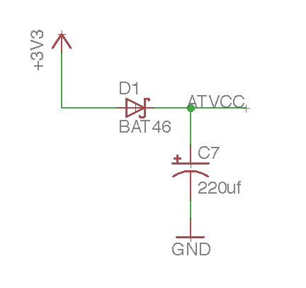
I want to be able to save the clock position in EEPROM if the power is failing, like when your changing the batteries. The DS3231 has its own battery backup and has a "/RST" signal that it can assert when it's detect a power failure so I just need to be able to provide power to the ATtiny85 long enough to write position status to the EEPROM. I'm thinking of something like this:
Where ATVCC is the VCC pin on the ATtiny85. The Diode should isolate the power to the ATtiny85 and the capacitor should supply power long enough for it to save the current clock position to EEPROM.
When I started this project I did not have the tools I really needed to analyze exactly how I was driving the clock so I went with the thought that the initial clock used a 1.5v battery so I should use close to 1.5v. This led me to use a low voltage motor controller. This worked well for me and allowed me to complete v1.
I've since obtained an oscilloscope and decided to see if I could eliminate the motor controller and use the ATtiny85 IO ports directly or use a bipolar H-Bridge. I found that the direct use of the IO ports, with 100ohm resistors, worked mostly ok and used less power than the H-bridges. This dropped average current draw from 0.75ma to about 0.45ma.
Then I tested using PWM for the clock pulses. This dropped the current draw down to just under 0.25ma with an added side effect that fast-adjusting the clock, as in a time change, is faster and smoother. (30 times normal speed)
All of the main components have some form of low power mode that I’m using to reduce power usage.
The ESP8266 has “Deep Sleep that allows it to use approximately 20 micro-amps. Deep sleep timer only lets you sleep for just over an hour at a time so I keep track of how much mode sleeping is needed and set deep sleep to wake without the radio turned on, saving power, if mode sleep is needed. During these intermediate wake-ups I apply drift compensation if its been computed.
The ATTiny85 has a “power down” mode where interrupts will wake it back up. Its woken on the falling edge of the 1Hz signal from the RTC and powers back down after the tick has been completed. An “idle” mode is also used during the “tick” processing while timers are used to wake from idle.
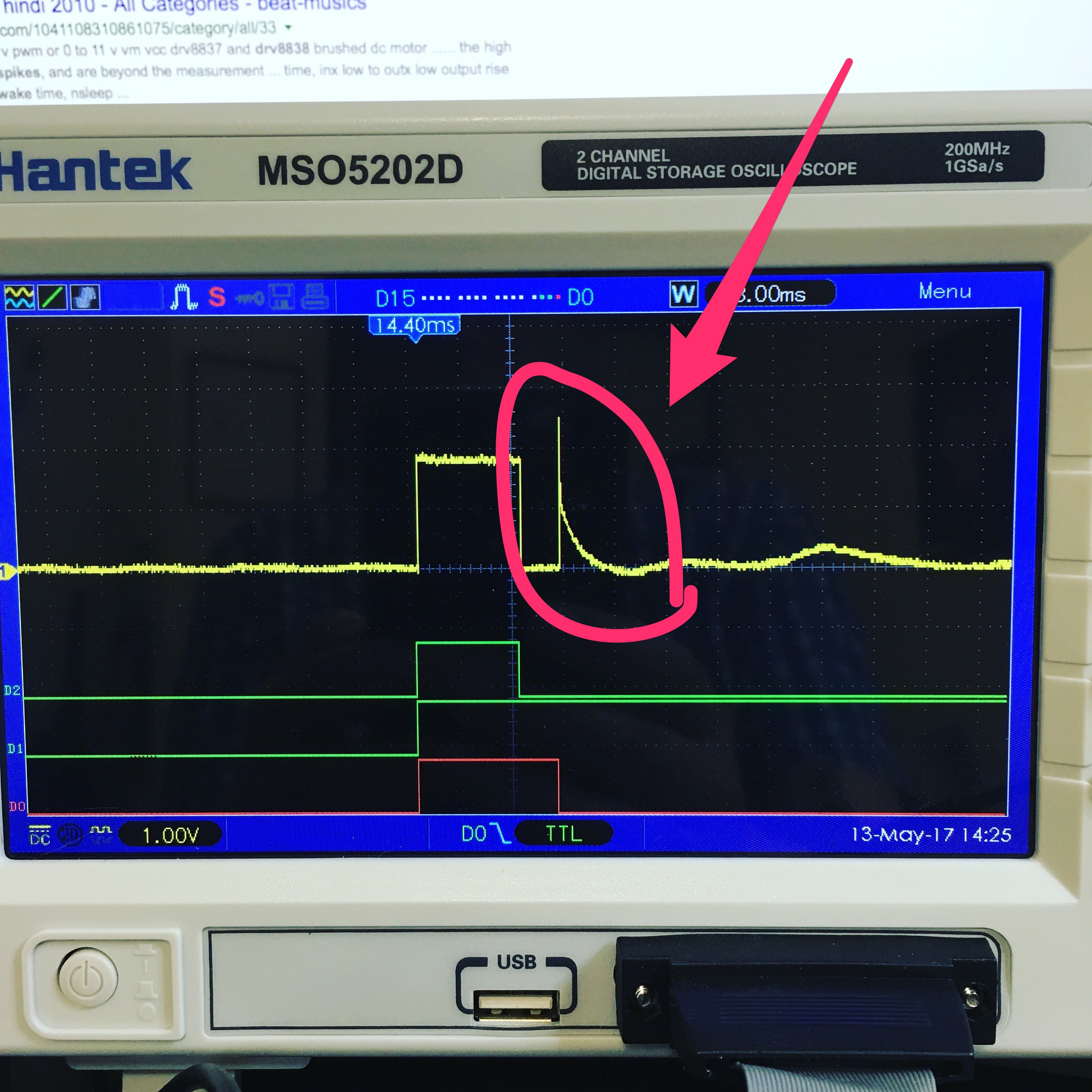
The DRV8838 has a sleep pin that the ATTiny85 activates after the tick has been completed. There is a delay after the tick is completed that is needed because while the DRV8838 is active it cancels any inductance caused spikes form the motor. If its put to sleep immediately after the tick finishes then there is a huge spike that causes the tick to mis-fire.
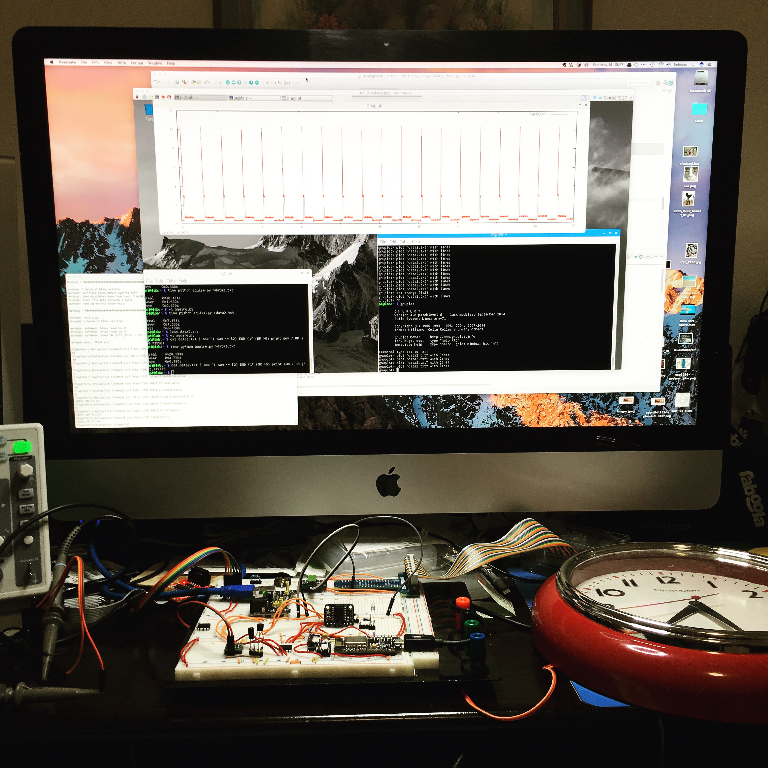
I measured the overall power usage and found the following: (these were measured before I added hourly drift compensation)
Measurements were taken with an INA219 current sensor module attached to a Raspberry PI and graphed using gluplot:

Sorry for the (really really long) delay! I used this core for attiny85 https://github.com/SpenceKonde/ATTinyCore and used the Wire library that came with it. Worked fantastically with the attiny85 using internal 1mhz clock. Also note that it wakes properly from power-down mode when receiving i2c communication.

Hi liebman,
Great project! I'm curious which library did you use on attiny85 side for i2c communication back to esp8266... I checked your github repo and it doesn't look like you published it. I'm working on another project where I need to pass the data attiny85->esp8266 (wemos d1 as of now) and trying to use TinyWireS library, but it seems that attiny85 drives SCL pin (D1 on wemos) low constantly and doesn't accept any incoming calls from esp... can't wrap my head around

 middelbeek
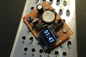
 Sven Gregori
 Est
Est
 Jan Waclawek
The 12S already has some pull-up resistors, specifically on the CH-PD, GPIO0 and GPIO15. It also lacks a 470 resistor in series on REST.
What modifications do I need to make?
I'm thinking of removing the R9, R12 and R13. Good idea?