 Maria Carlina Hernandez
A people counter is a device that used to measure the number of people traversing an entrance, hallway, street corner, etc. If you need to know how many people exist in a space - this is your simple solution. Mostly used in retail stores, shopping malls, and smart office buildings, this counting technology has provided insight to how shoppers/employers behave.
How is the people counter application applicable to you (other than just being really cool technology)? Imagine you're the owner of a shop; this counter would will alert you to daily visitors, the walking paths taken when inside, where they stop, and how long they linger at in a place. Wouldn't you like to know what materials gain the most attention; possibly being able to reposition products geographically to increase awareness to benefit your customers needs and your bottom line?


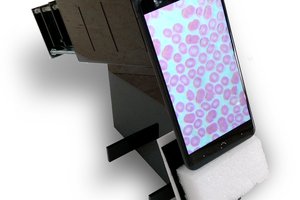
 aiscope
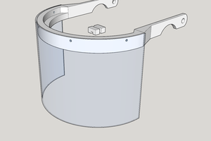
 T3rr0rByte13
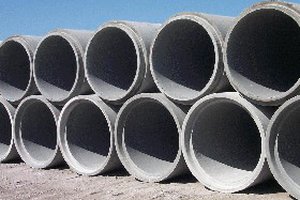
 Reilly Scott
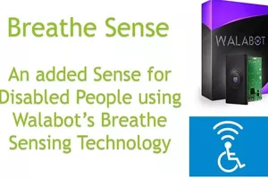
 Dhairya Parikh