 Carlos Garcia Saura
Signal amplification and conditioning has been implemented with the following circuit:
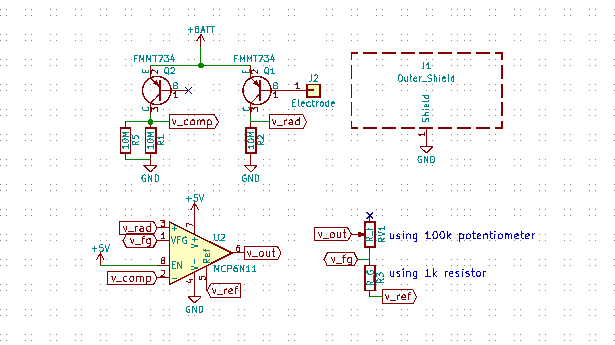 Amplification is achieved with a pair of Darlington transistors, one to amplify the radiation signal and the other to compensate the effect of temperature over transistor gain (see log entry 5).
Further amplification and signal conditioning is achieved with an instrumentation amplifier. As opposed to operational amplifiers, instrumentation amplifiers produce an output that is linearly proportional to the difference between the input voltages. This allows to compensate for temperature, amplify and drive the output signal, all in a single step.
An important detail to note is the need for R5 to tune the output voltages. In theory both signals should be equal when no radiation is present, but we have observed that this is not the case due to transistor manufacture tolerances. If the reference signal is greater than the output signal, it could inhibit radiation detections in some circumstances.
In our tests we have seen that Vref is usually higher than Vsignal, so it was necessary to place an R5 that drops Vref slightly.
There is also a potentiometer (RV1) to allow the rescaling/calibration of the output signal, the maximum can be mapped to any value in the 0-5V range. This allows direct interface with Arduino and other platforms.
Discussions
Become a Hackaday.io Member
Create an account to leave a comment. Already have an account? Log In.