 Craig Watson
Background
A brief overview of microfluidics
Microfluidics are often hailed as a revolution in biology, akin to how the transistor and ICs revolutionized electronics and computing. Chips can be designed to run many different kinds of lab experiments, with the advantage that they use much lower volumes of reagents, and are usually faster and more accurate than "conventional" assays.
Some common applications of microfluidics include diagnostics (e.g. detection of disease markers from a single drop of blood), drug screening, DNA sequencing and cell culture. This Wikipedia article gives a good introduction to the field.
Practically, fluids have to be pushed around the chips somehow. There are several ways to do this. One is to use passive flow, which relies on the affinity of the fluid and the substrate to pull the fluid along. This is used for example in glucose test strips, which are basically strips of paper that wick a drop of blood to an electrochemical sensor.
Another -- very cool -- way of moving fluids around a chip is electrowetting, which in a nutshell consists of applying a high voltage to electrodes on the surface of the chip to make a given electrode more hydrophilic, thus allowing you to pull a droplet of water along. A great example of this is OpenDrop.
Finally, fluids can be pushed around by air pressure. This is usually accomplished either with a syringe pump, which establishes a given flow rate, or with a source such as a pump and pressure regulator, which impose a given pressure.
There are of course other methods, but these are the most common. Without going into too many details, it is this last method -- pressure-driven flow -- which we need to operate our microfluidic chips. In our lab, we use these chips to culture cells in a way that simulates "real-life" tissue. This allows us to carry out experiments to better understand how cells interact in vivo, while keeping them in a highly controlled environment, and allowing us to run many experiments in parallel with relatively little manual labor.
If you are interested in learning more about microfluidics and how they can be applied to biology, here is a great introductory lecture on the subject. The type of chips that we use (and is mentioned in that lecture) are constructed of two layers of PDMS. These are great for our application since they make it easy to integrate valves into our designs, allowing us to route fluids to specific parts of a chip, and run many different experiments in parallel on a single chip.
Control systems for PDMS chips
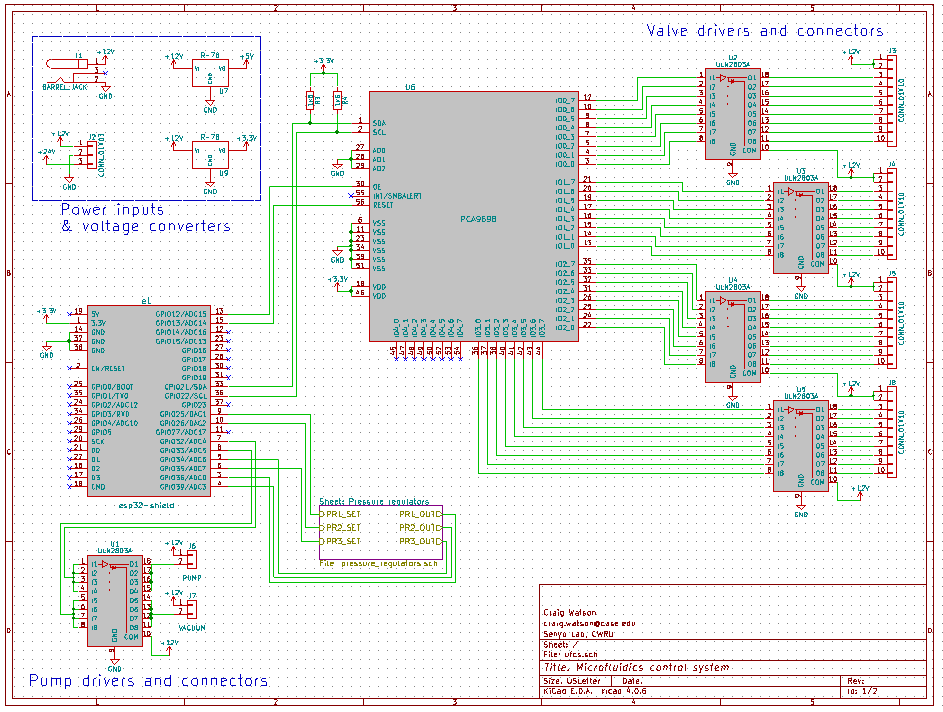
In short, to operate our chips, we need:
- A positive pressure source
- A vacuum source
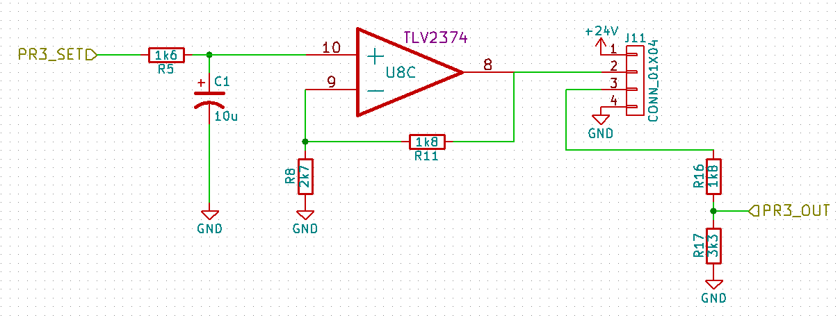
- A way to regulate pressure (at three different pressure levels, including vacuum)
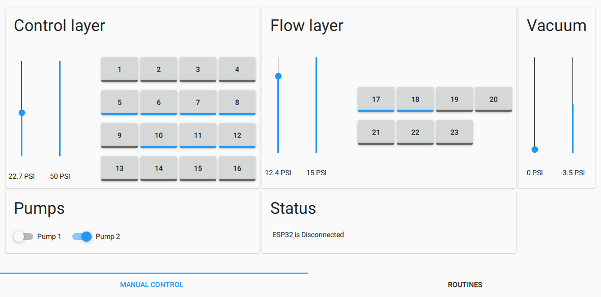
- Valves to switch pressure on & off on up to 32 lines independently
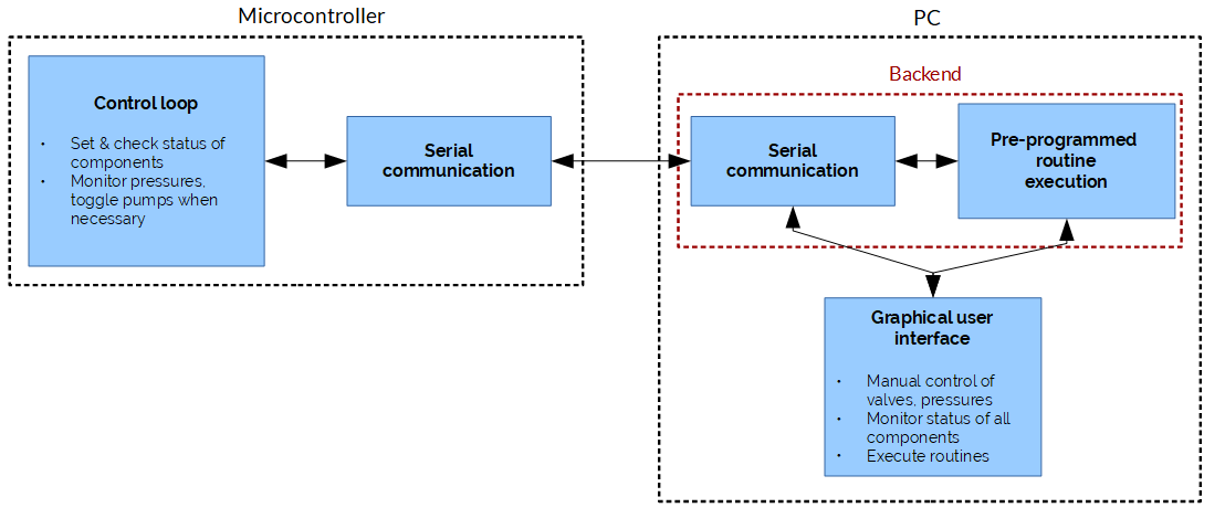
- A way to automate everything
While this is specific to our application, it should be noted that most of these requirements (especially numbers 1 and 3, and to some extent 5) are common to every lab using similar microfluidic chips, so this project could benefit many other labs and even DIY biologists.
Now, there are commercial solutions for controlling microfluidics. You get either a modular system with separate pressure sources, valves and so on, or a nice all-in-one unit. Unfortunately, all of these tend to be rather expensive (5-10k USD or more), and not always suited to one's exact application. For example, you might find commercial controllers with 16 valves; if you need just a few more, then you have to shell out an extra few thousand dollars for a second valve control module.
Therefore, many labs go for a more DIY approach.
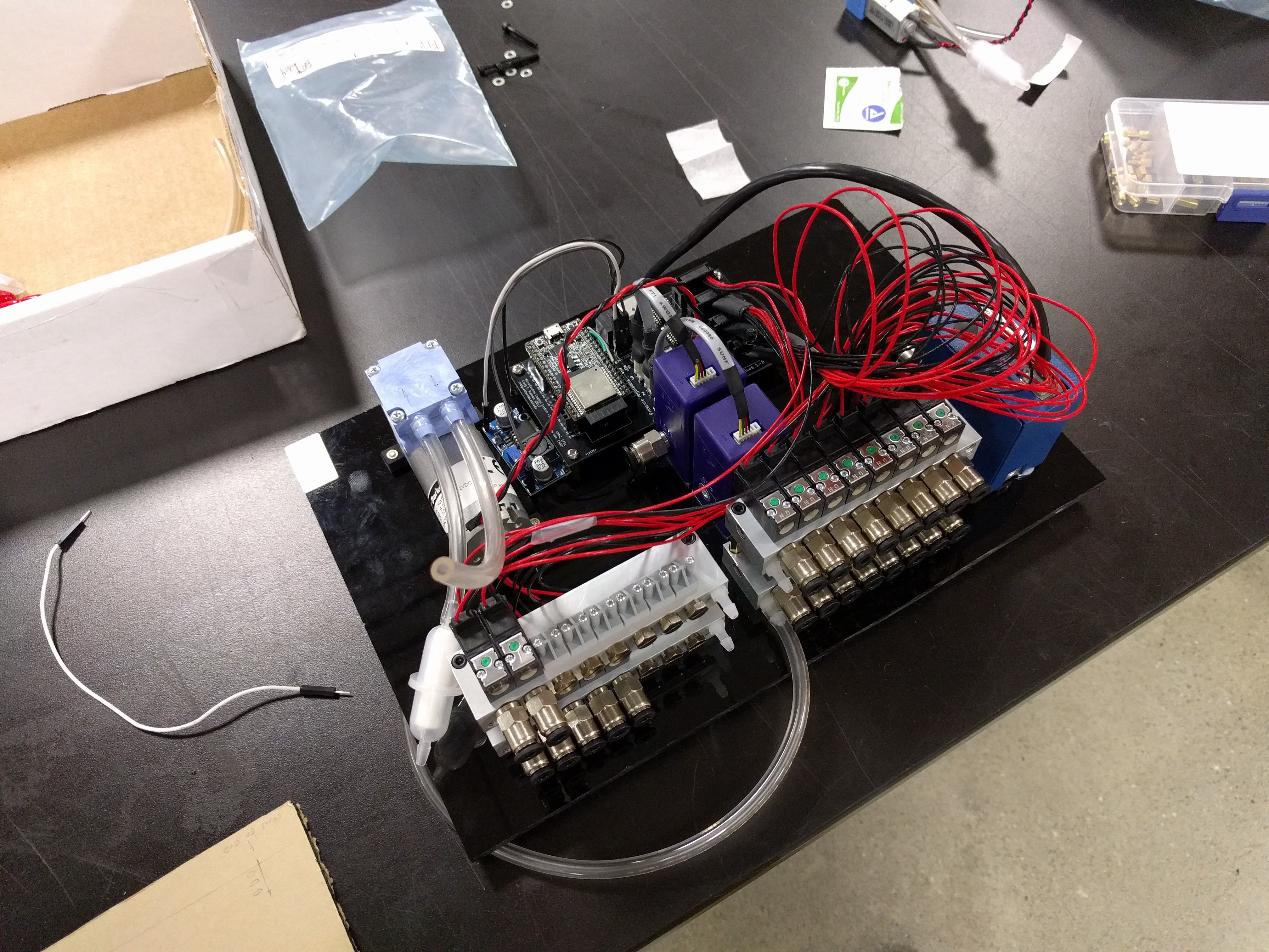
Typically, the pressure sources are either central compressed air for the fancy labs, or large pumps and tanks for the plumbing-impaired labs. The pressure is then adjusted using a manual regulator and the air is split by a manifold to the many different lines, each of which is controlled either with manual valves, or solenoid valves...
Read more »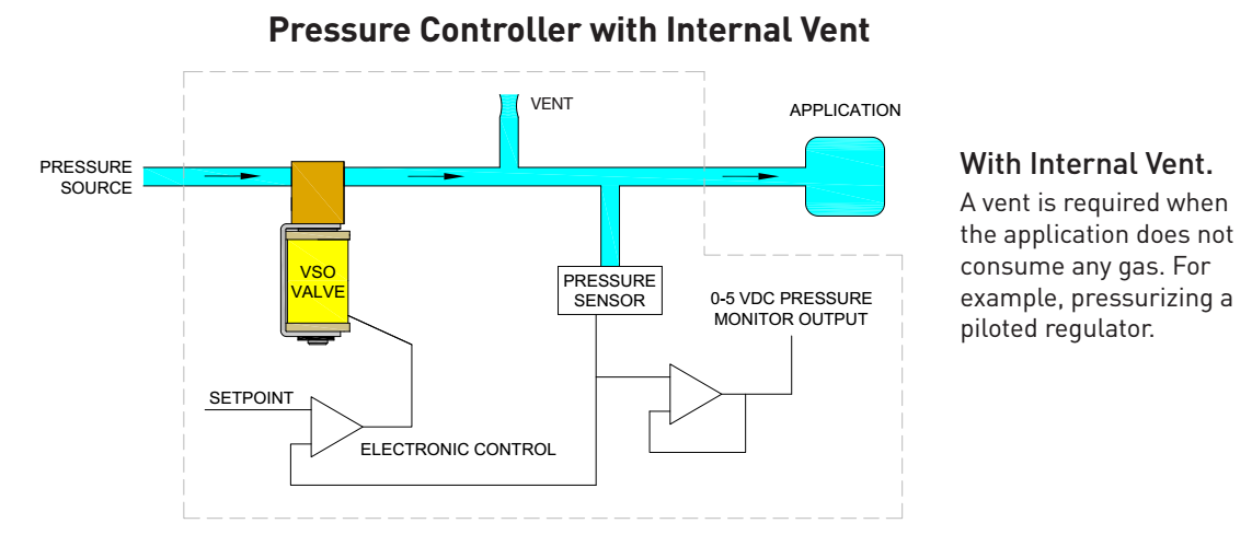


 OzQube
 Quinn
Quinn

 DigiGram
So I've been thinking of working on something similar for my research, do you want to collaborate and integrate this with my microfluidic design tools ?
Tool: https://3duf.org/
Publication: https://www.nature.com/articles/s41598-019-45623-z