 deʃhipu
I assembled the first prototype, and started programming it: connected my stlink, ran the Adalink program to wipe the chip and flash the bootloader, and the UF2 disk came up. I first tried with a custom firmware with the flash enabled, but for some reason that didn't work. Weird. Oh well, I decided to at least test the rest of the board, and leave flash for later, and flashed the original Trinket M0 firmware. That seemed to work.
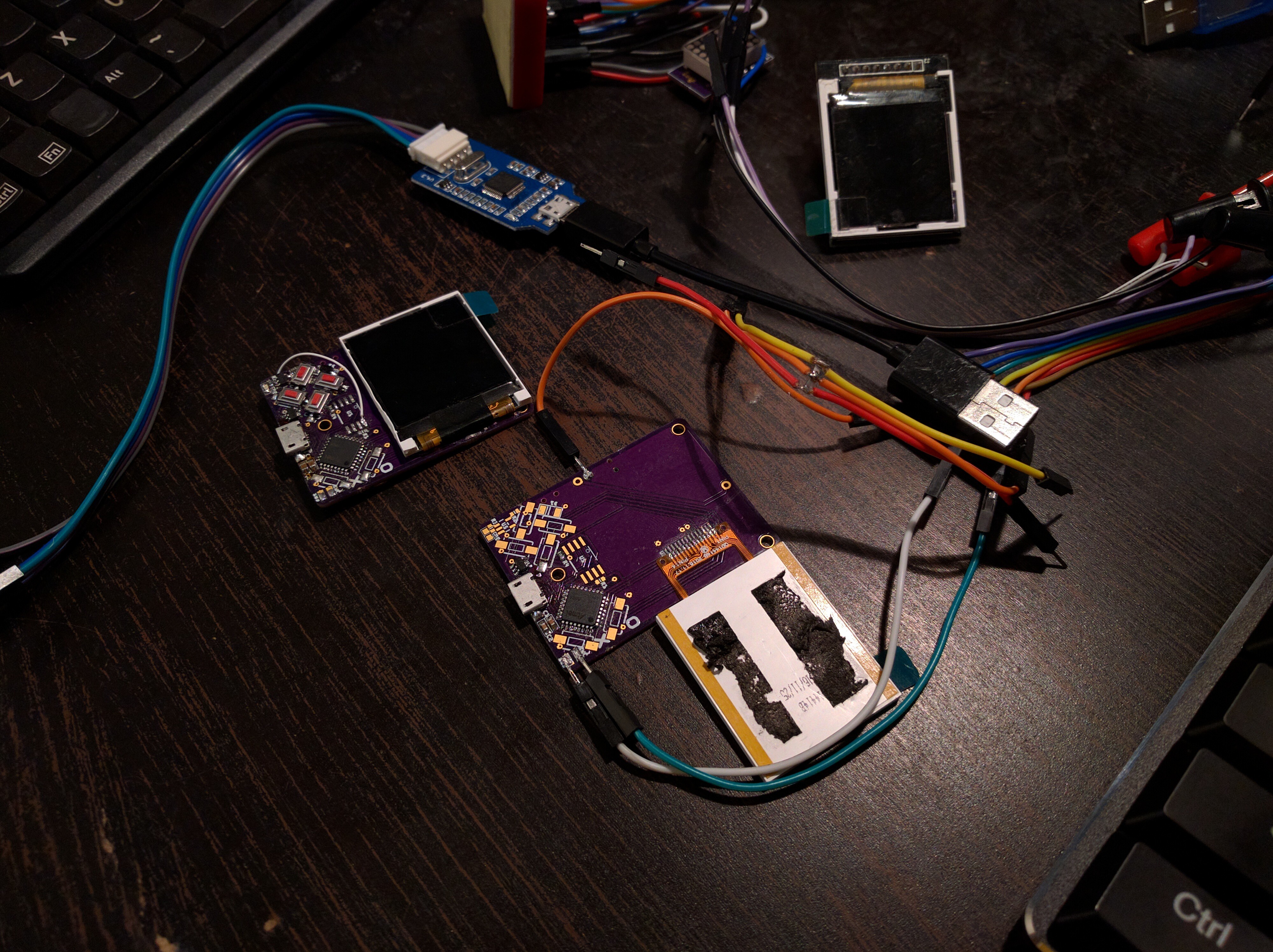
So I copied the libraries for the ST7735 display, and tried to fill the screen with a solid color. Nothing. Tried different SPI speeds. Nothing. Unglued the display to examine the connections — they seem fine. Added an external pull-up resistor on the reset line. Nothing. Connected wires to see the signal in the logic analyzer — the signals look fine. Connected those wires to a display module with the same type of display — nothing.
I put the same program on a Trinket M0 and connected that display module, with the same connections as I made (CS to GND, RST pulled up, etc.) and to the same pins as on my PCB, and it works. So the code and the wiring seem correct.
Then I decided to de-solder the flash chip, since it didn't work anyways, and afterwards when I connected the board to USB — it worked! So maybe the flash chip was connected wrong or somehow faulty? Happy that it works, I left it for a while, and when it came back to it, it didn't work again. What?
I looked at all the connections under a magnifying glass, I de-soldered the two fire buttons, to have better access, and touched all the mcu pins with the soldering iron, to make sure the connections are solid. Connected to USB, works. Stops after a moment.
So I tried many other things — replaced the chip, replaced the display — every time this thing works as long as it's hot, and stops working when it cools down. What could possibly be wrong? Maybe a trace on the PCB has a micro-fracture, which adds enough resistance for the signal to be too weak for the display, but enough for the logic analyzer, and when I heat it, the copper expands and the fracture disappears? No idea.
But I decided to make a second PCB, this time only with the essential parts: the chip, two caps, USB socket, voltage regulator, resistor for the back-light and the display. I assembled it, and connected it for programming — now my stlink can't seem to be able to wipe the chip in order to upload the boot-loader. I can send the erase command, but it doesn't seem to actually erase the flags. Sigh.
I'm calling this a day. Tomorrow I will swap the chip for an already programmed one, and see if the second board works.
Discussions
Become a Hackaday.io Member
Create an account to leave a comment. Already have an account? Log In.