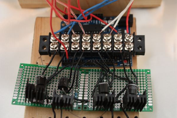
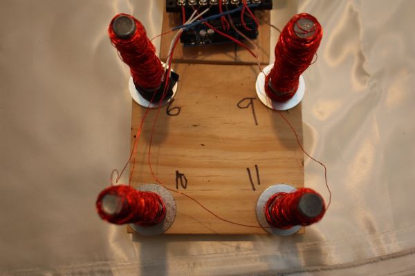
This project aims to make an electromagnetic levitation apparatus that automatically stabilizes to combat opposing forces. The system includes 4 electromagnets on the corners of the structure. A gyrometer is constantly taking measurements and will detect if the levitating platform starts to tilt. If this happens, the system will send 12 volts through specific electromagnets causing the statue to levitate a few inches off of the structure. Using Maxwell Tensile Strength calculations to find the magnetic flux, the apparatus can theoretically lift 11 kilograms 1 inch into the air. Depending on the tilt of the statue as measured by the gyrometer, the electromagnets will compensate by sending added voltage in the opposite direction. This is done by 4 transistors and pulse width modulation control using an Arduino. Pulse width modulation is a type of digital signal that helps to vary voltage to the electromagnets. Therefore, the statue will stay flat regardless of any movement. The experiment was conducted to see if there would be a statistically greater angle at which a block on a platform falls over with the apparatus compared to the angle without it. The research hypothesis states that the model statue with the apparatus would fall over at significantly greater angle than the model statue without the apparatus. The null hypothesis states that there will be no significant difference. The results show an increase in angle at which the model statue falls over. Therefore, there is an increase in stability with the electromagnetic device. Without the apparatus, the model statue fell over at a mean angle of 14.286°. With the apparatus, it fell over at an average angle of 24.741°, a 73% increase in stability. The p-value calculated with a one-tailed independent t-test is 1.371*10-23 which is less than the alpha value, 0.05. Thus, the null hypothesis is rejected and the research hypothesis is supported. Therefore, the data supports that the apparatus is successful in stabilization of the platform.
Introduction
Rationale:
Current stabilization techniques are similar to the ones used in buildings in San Francisco to prevent damage from earthquakes and cost upwards of $265,000 (Anderson). Electromagnetic stabilization would be a cost-effective solution that would involve the base detecting an earthquake with a gyroscope/accelerometer that reads the X, Y, and Z rotational values and the surface responding with movement in roll, pitch, and yaw (Invensense). The levitating square-shaped surface would consist of a magnet at each corner and the aforementioned gyroscope. These values would be transmitted to an Arduino microcontroller chip (Diodes Incorporated, ON Semiconductor). Pulse Width Modulation uses a digital signal to control the current supplied to the 4 electromagnets in the base. Also, with four electromagnets and a 12 volt power supply, the structure can theoretically lift an 11 kg surface (Schmipf, Vogel).
Objective: The apparatus will determine if an electromagnetic levitation apparatus can improve the stability of a statue as measured by the angle at which the model statue falls over and a possible explanation for why.
Expectations: The model statue that uses the apparatus will fall at a significantly greater angle than the model statue that doesn’t use the apparatus. Thus, the apparatus will increase stability.


 T0mte
T0mte
 Slavko Glamocanin
 Florian Wilhelm Dirnberger