 deʃhipu
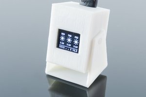
The Micro:bit is a pretty decent platform for teaching kids to program, but you can't really make arcade-style games for it. You only have two buttons and a 5x5 display. Perhaps enough for a very small snake game, but that's pretty much it. That's why I started working on #PewPew FeatherWing as an alternative platform, but at some point I started wondering if it's really impossible to do it on the micro:bit.
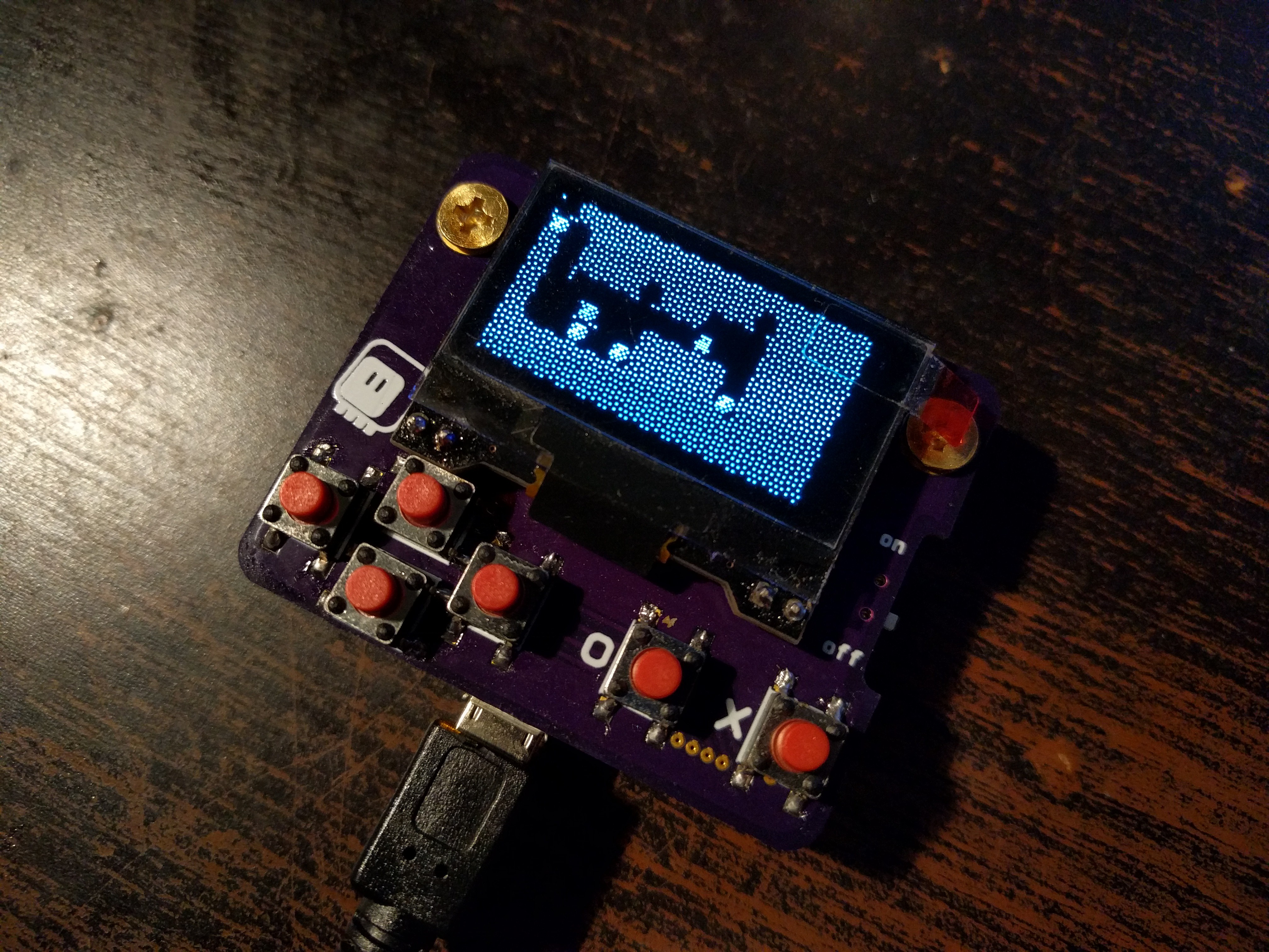
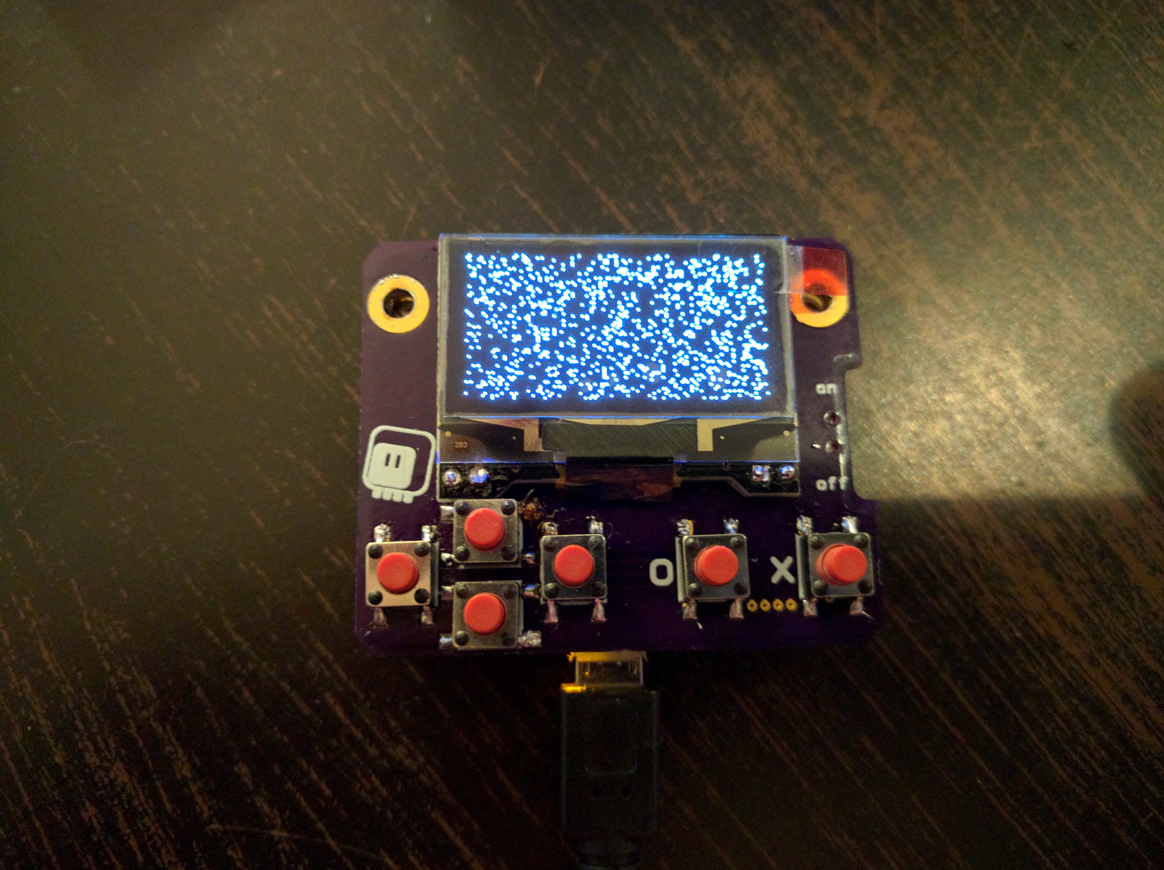
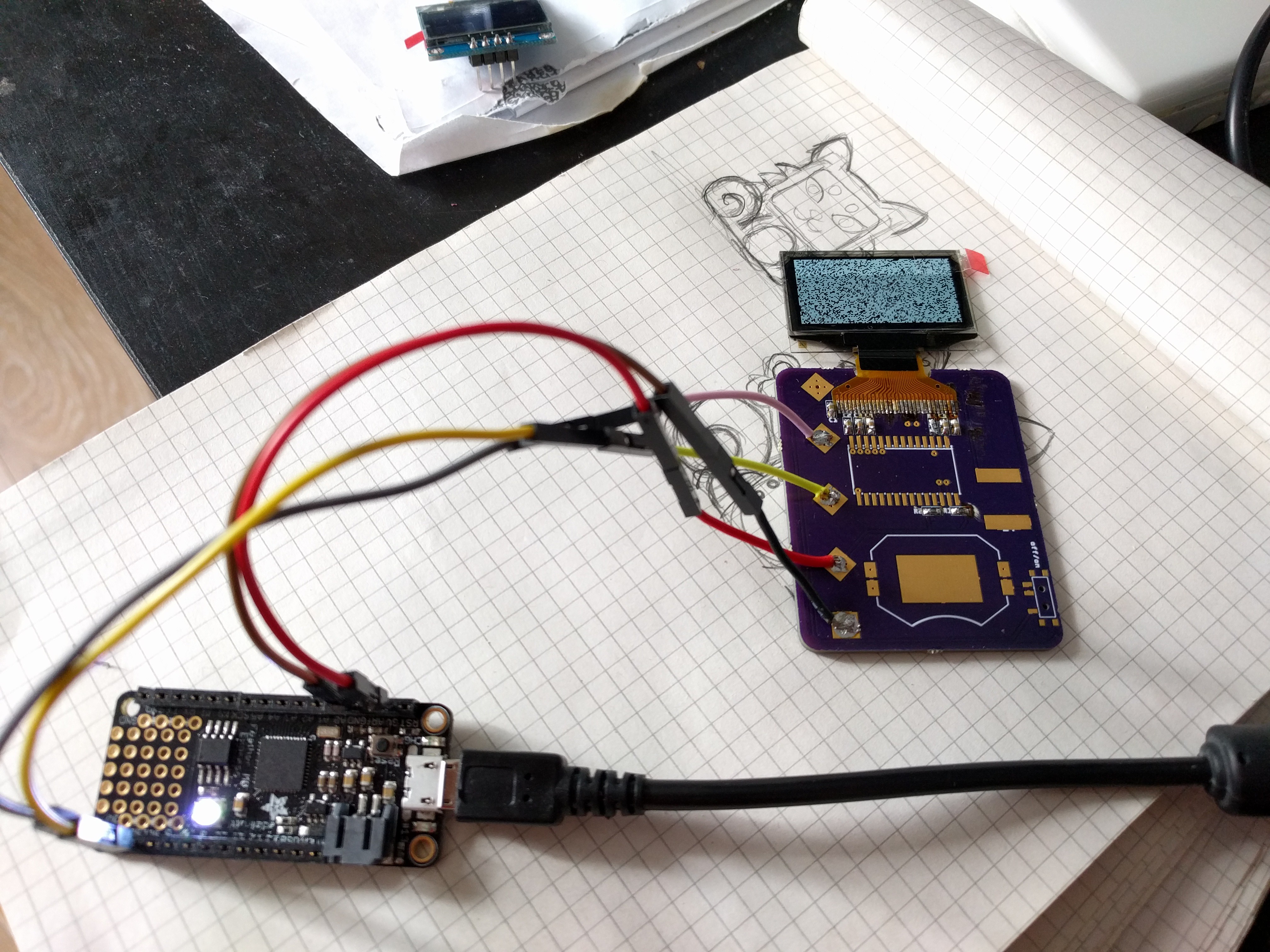
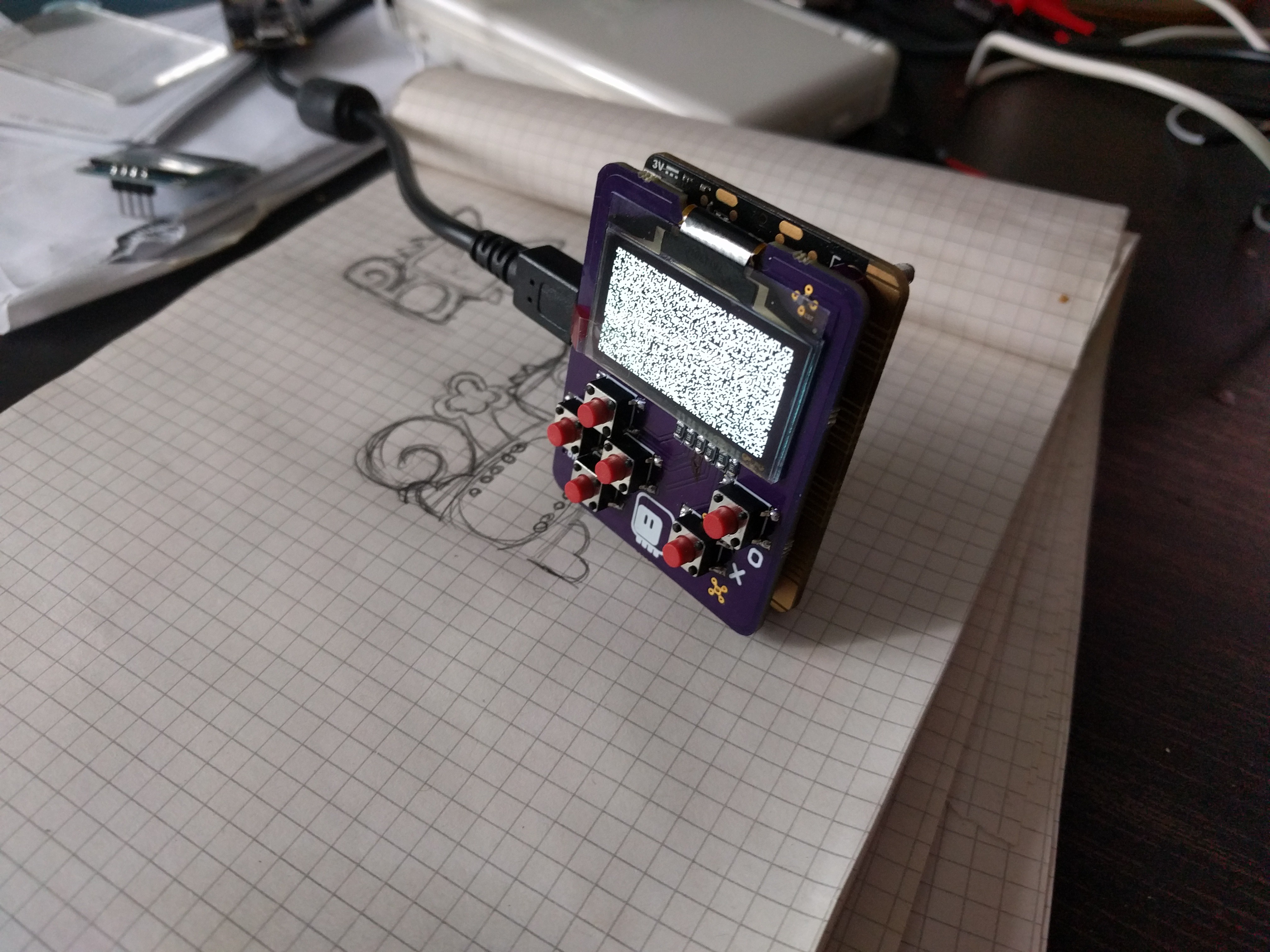
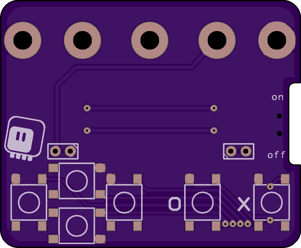
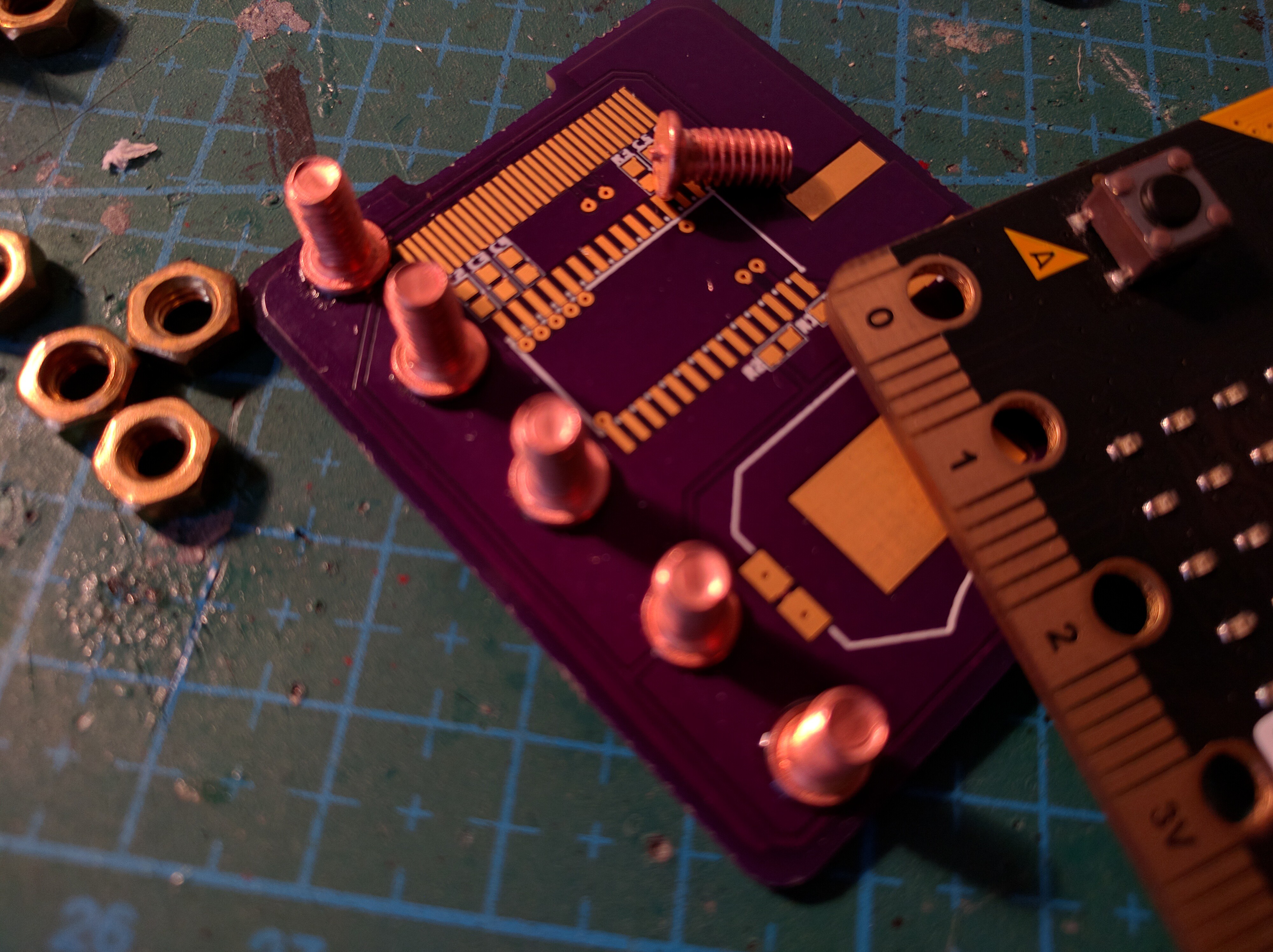
When the most recent version of micropython got the ability to use any pins for I2C, I realized that I can finally connect a display easily. I could use a HT16K33 and a 8x8 LED matrix like on the PewPew, but I decided to try something else — a monochrome OLED display, similar to the one used on many Arduino-based game consoles.


 ACROBOTIC Industries
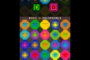
 Fluxly
 jlbrian7
 Jeremy g.
Hi. great stuff. Can this now be used for a car arcade game like https://carxdriftracing2apk.net/