0%
0%
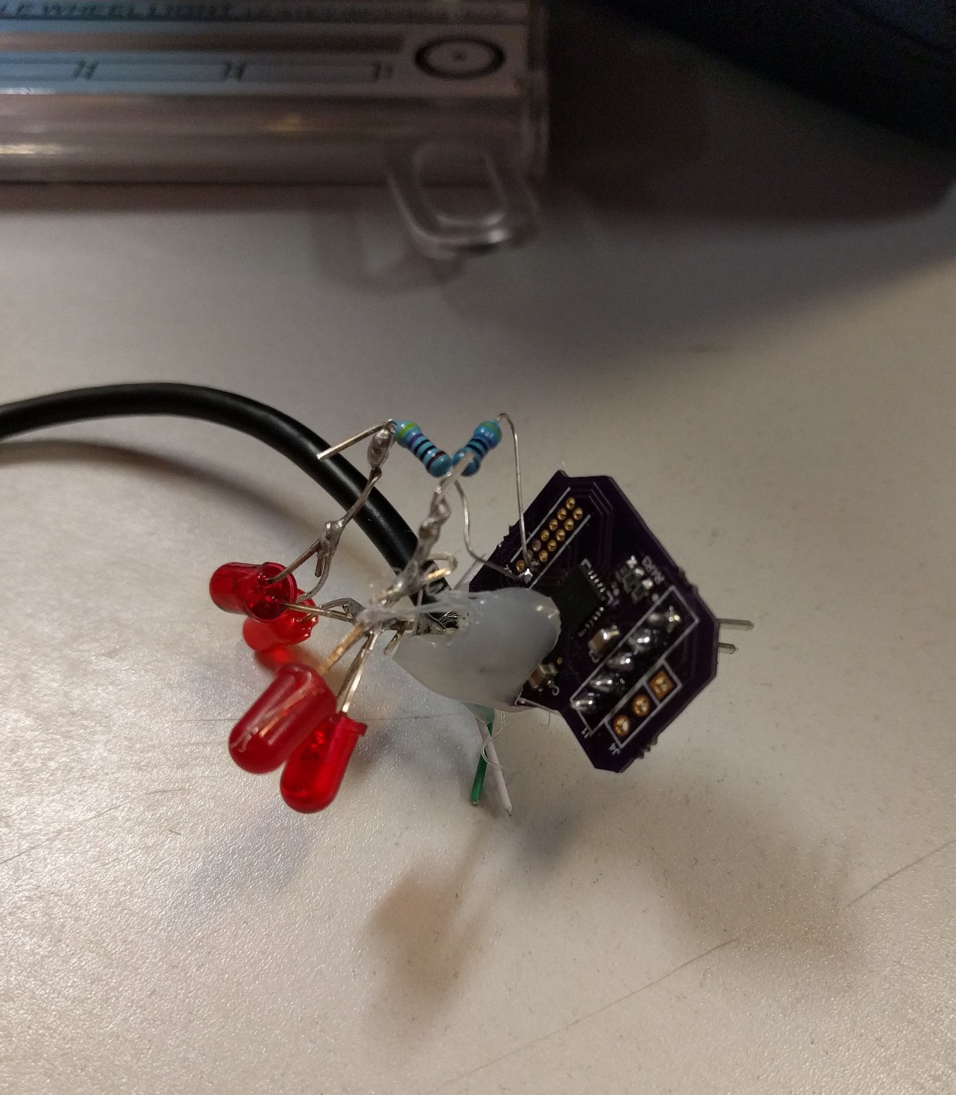
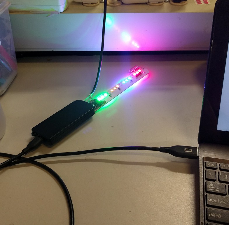
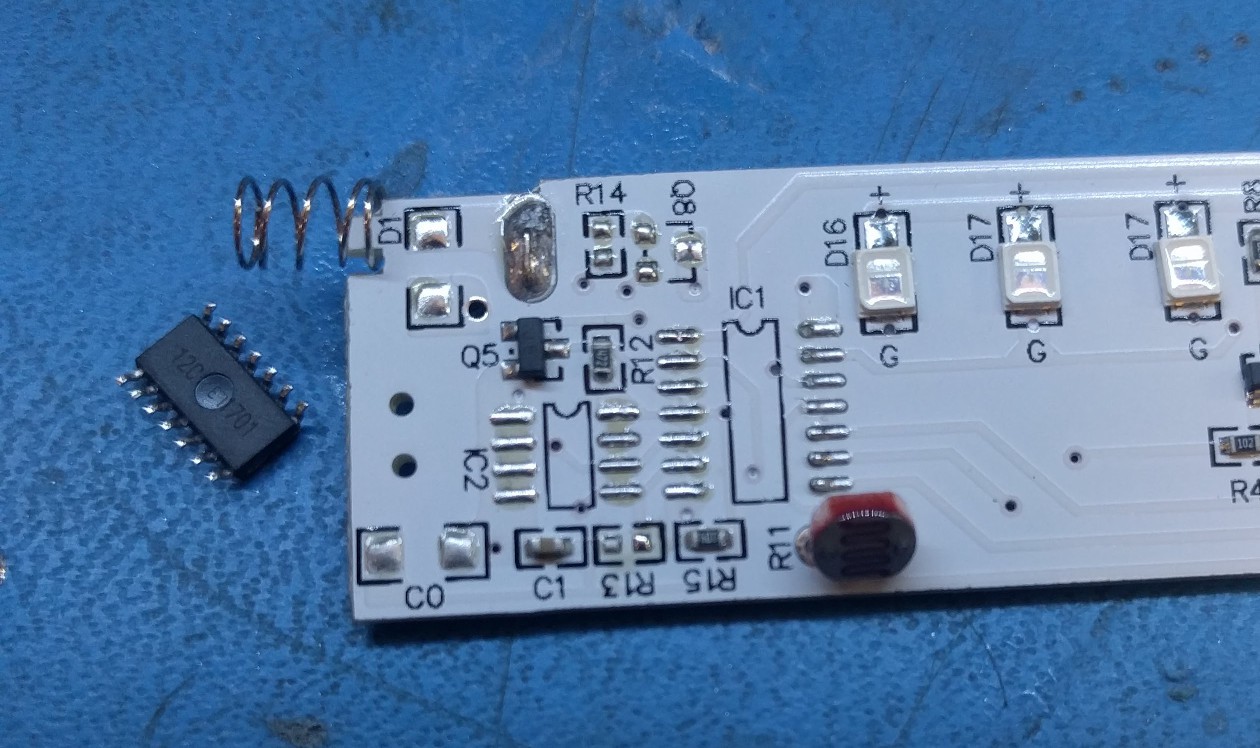
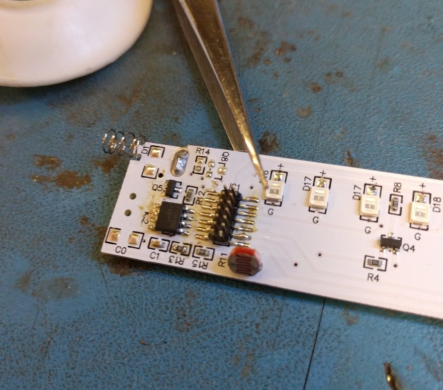
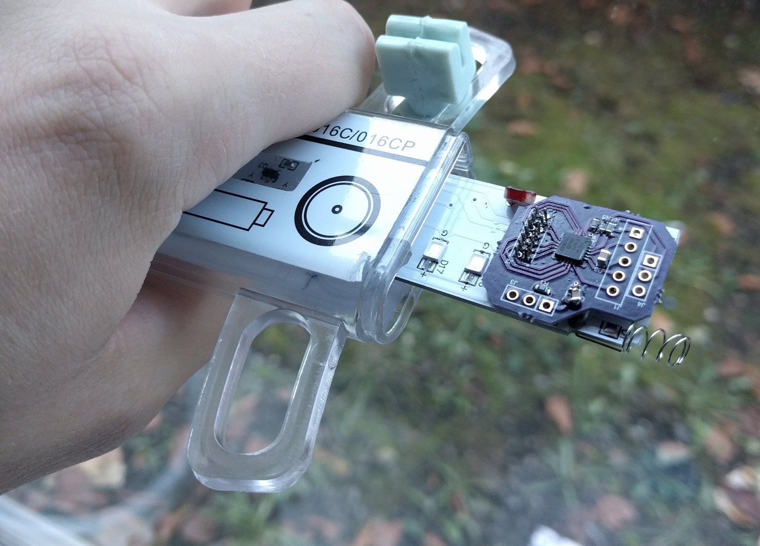
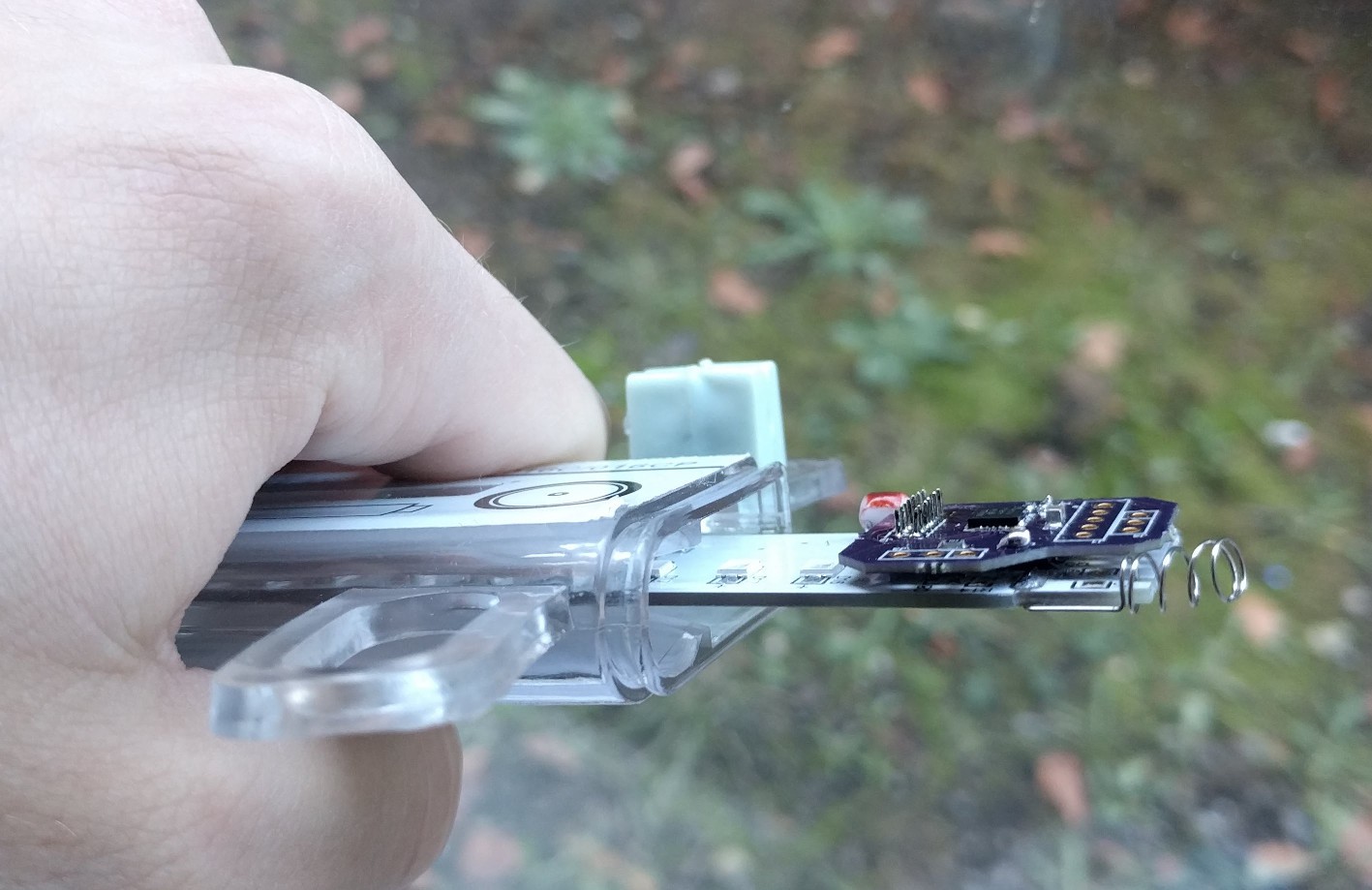
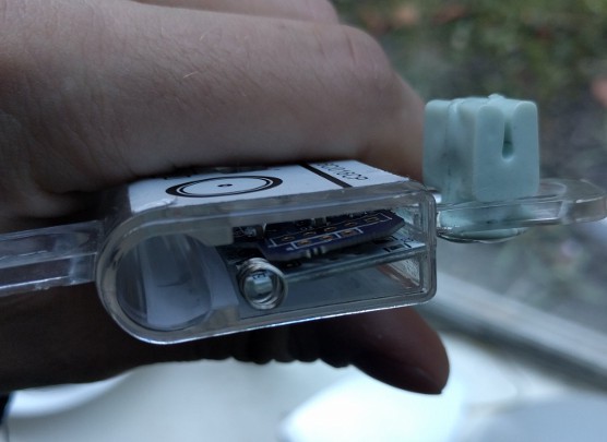
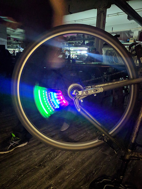
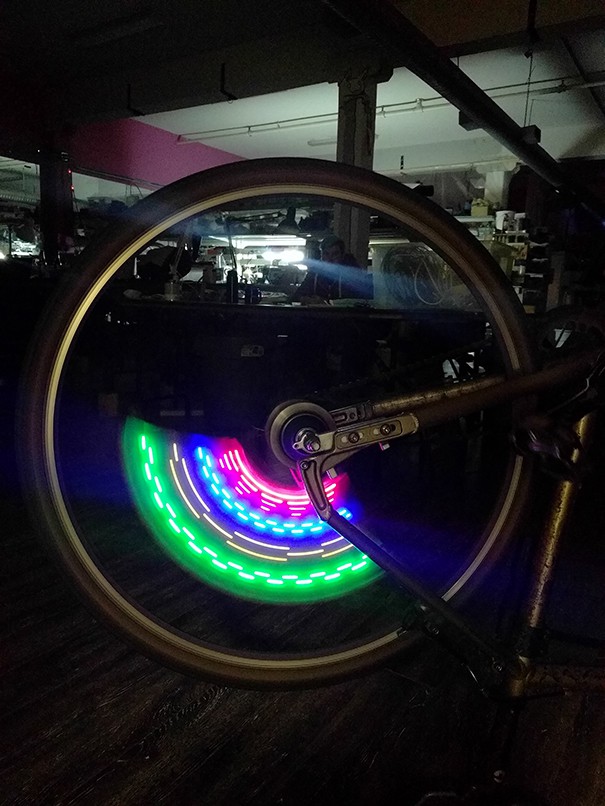
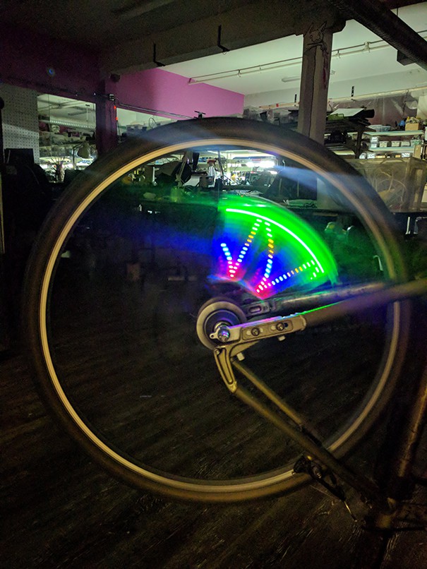
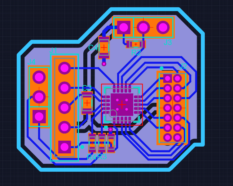
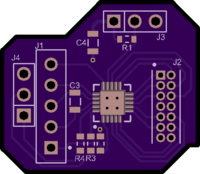
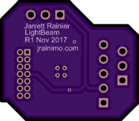
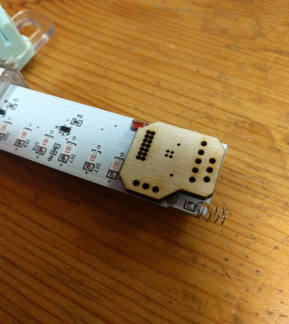
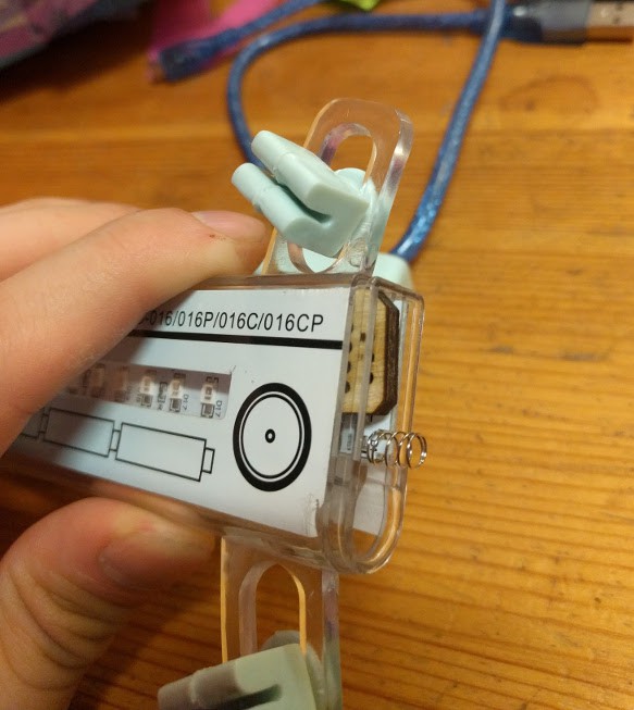
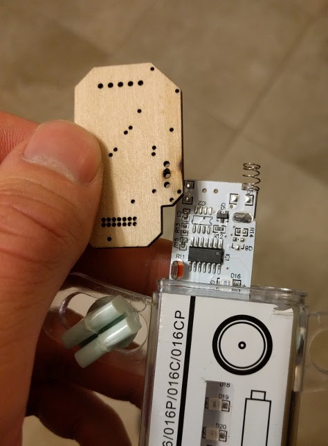
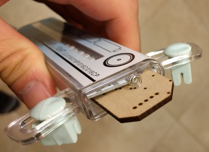
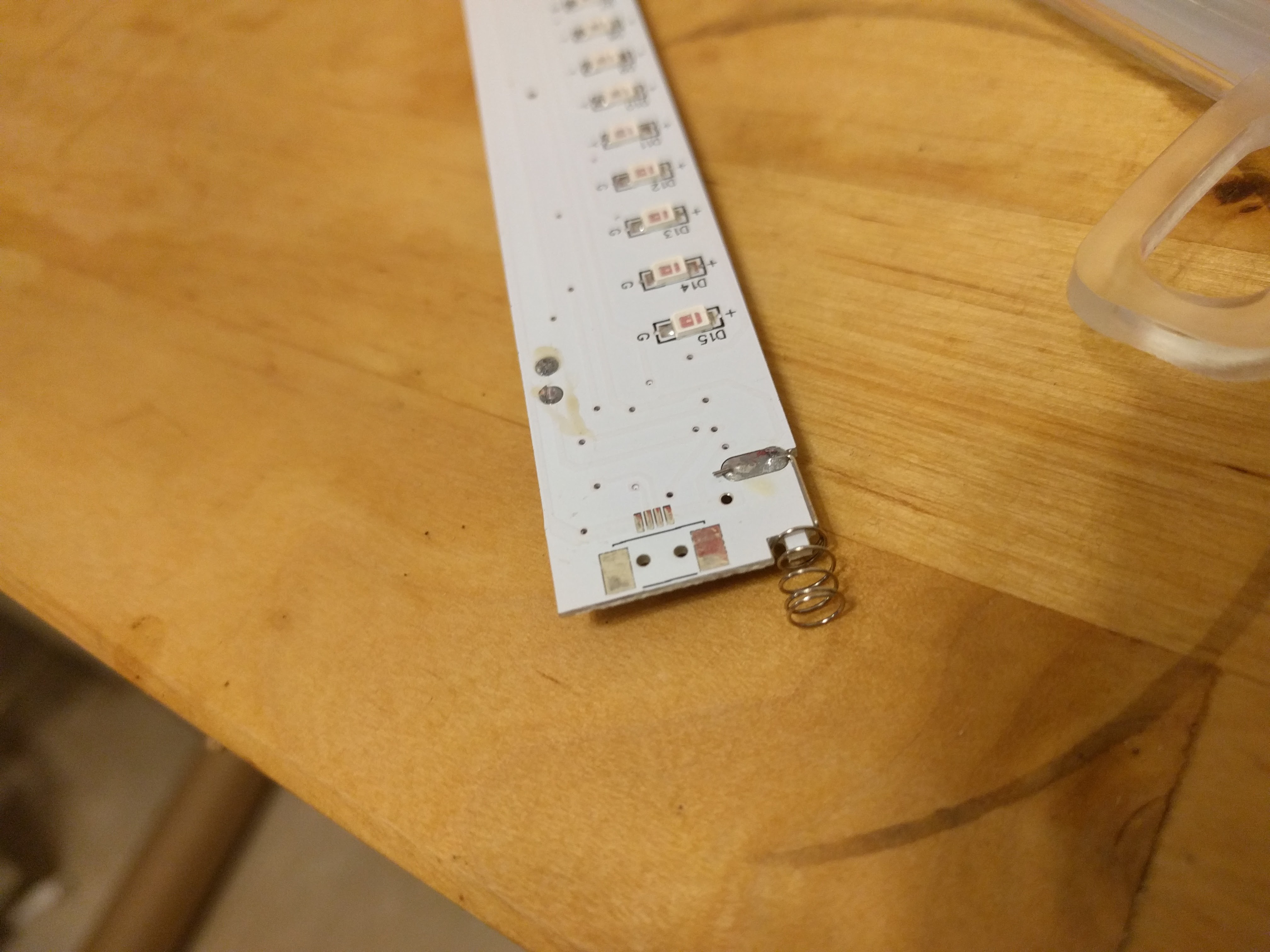
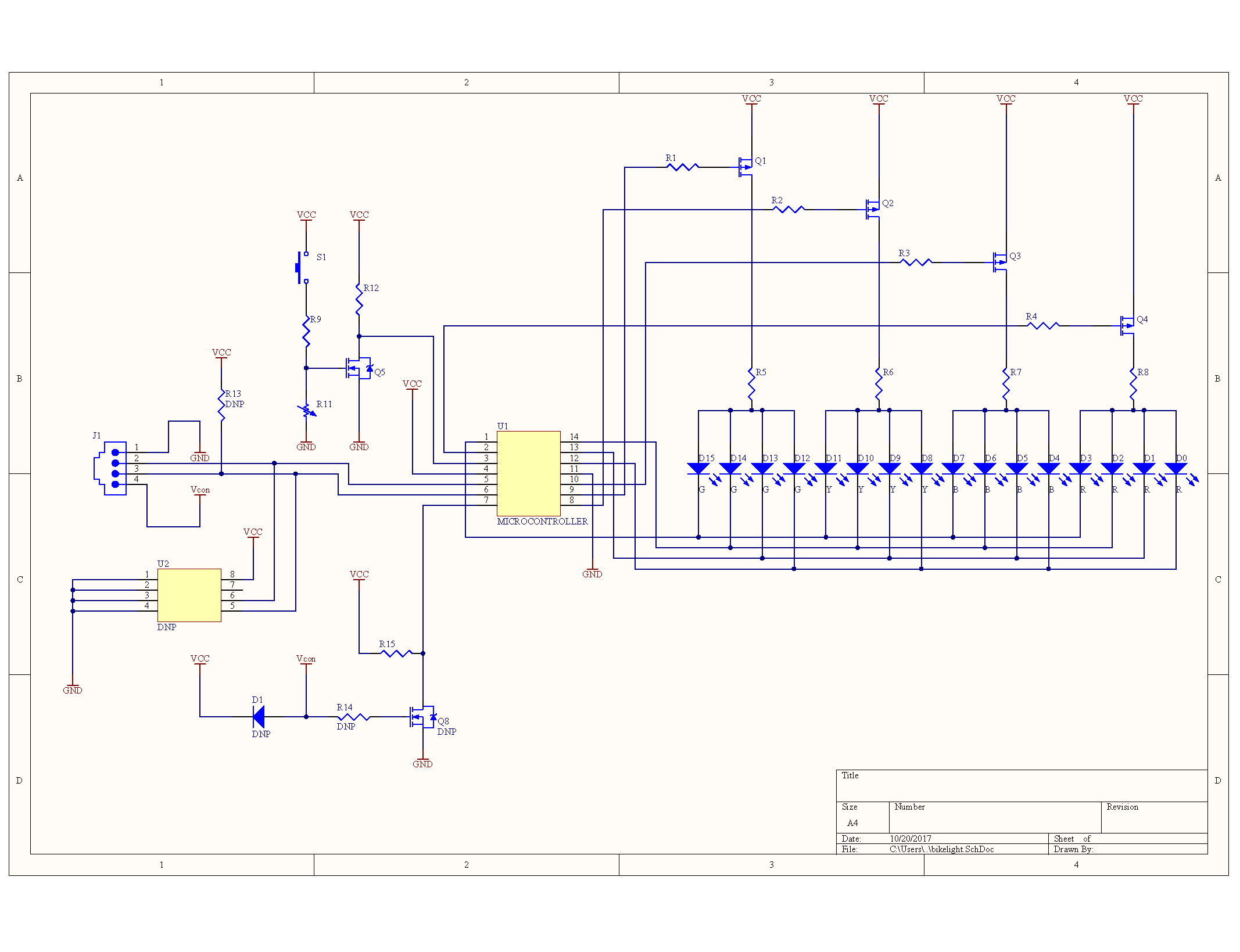
Hacking the Bike Light
Adding the necessary to the extremely economical illumination
 Jarrett
Become a Hackaday.io member
Already have an account? Log in.
Just one more thing
To make the experience fit your profile, pick a username and tell us what interests you.
Pick an awesome username
hackaday.io/
Your profile's URL: hackaday.io/username. Max 25 alphanumeric characters.
Pick a few interests
Projects that share your interests
People that share your interests


 mrpendent
 Kevin Arne
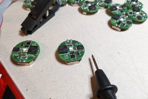
 schlion
@davedarko Lol.
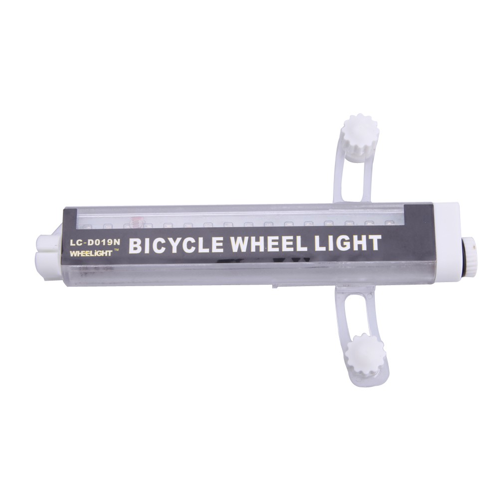
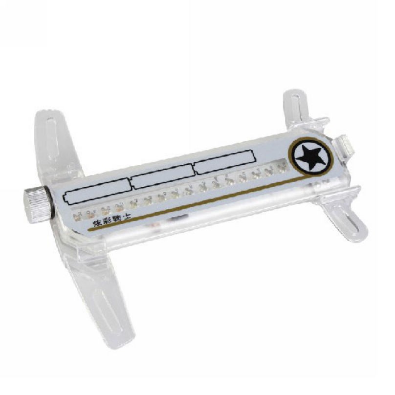
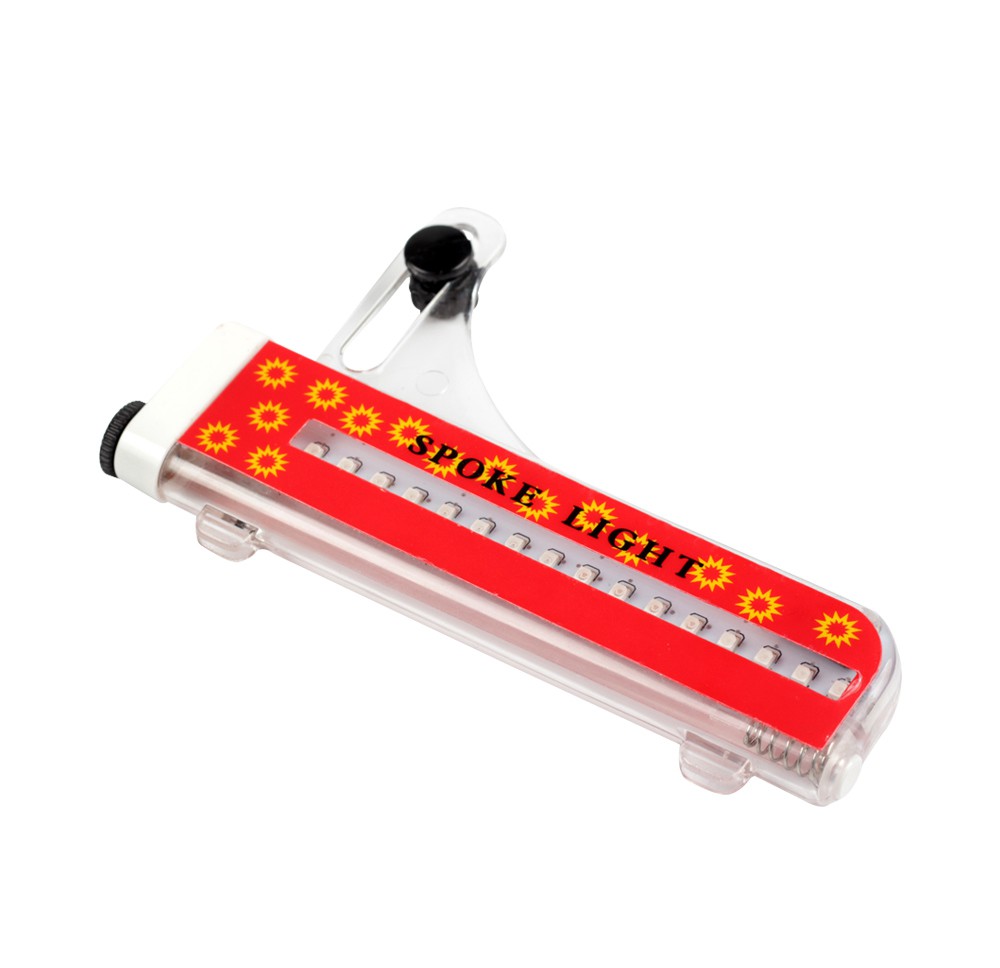
I've got the Leadbike A07 for my son: htoutp://en.leadbike.cn/index.php?id=2022
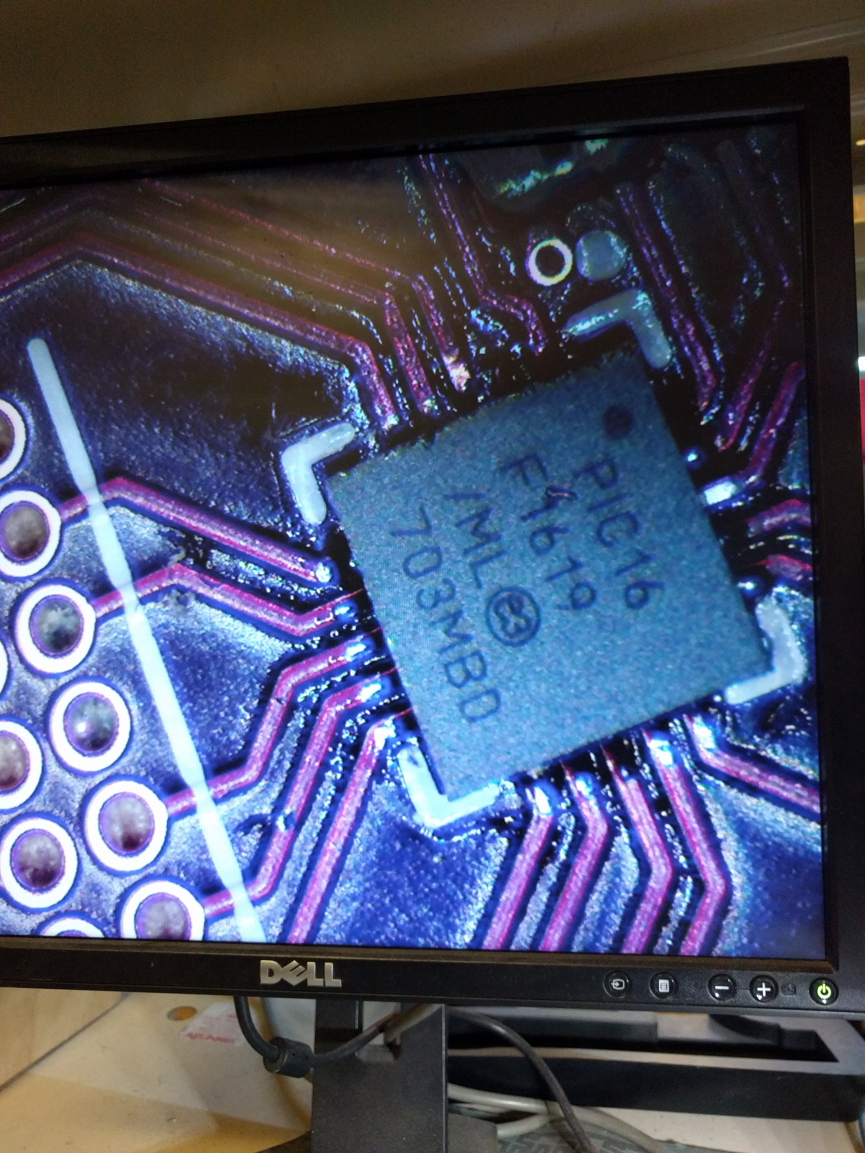
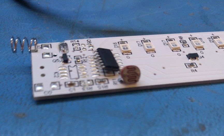
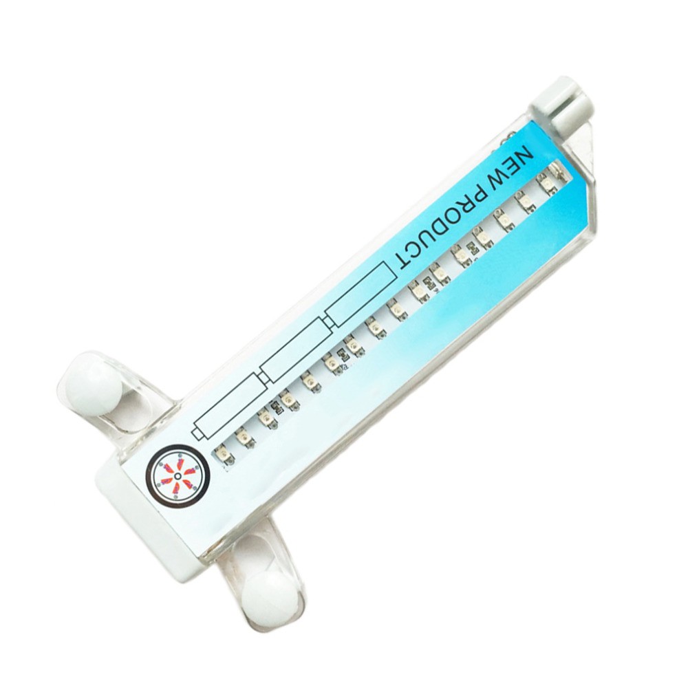
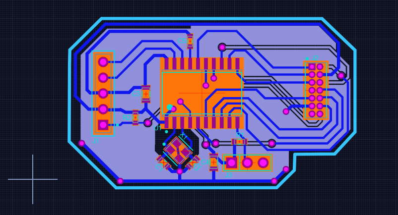
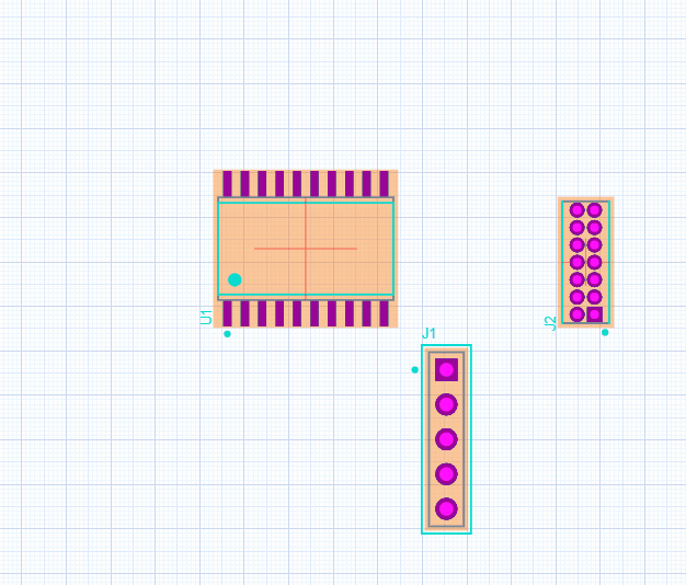
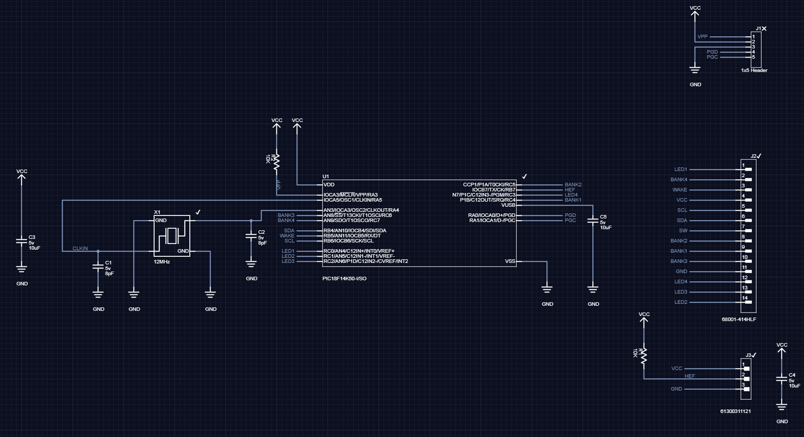
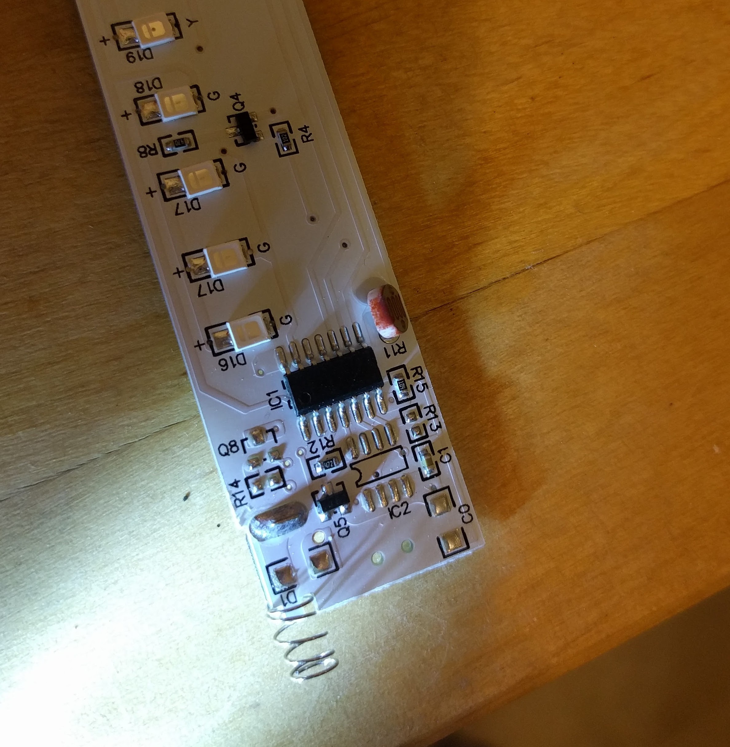
It's funny how these manufactures keep the source code closed, although the use a lot of "inspiration" from others. I would like to reverse engineer the USB protocol so I can write a software for Mac. Any idea what's inside (EPROM or MCU ?). Perhaps buying something with a programmable controller (eg. YQ8003) is a faster way forward? https://github.com/nomeata/bSpokeLight
PS. I'm late to the party, but hey things seem to live for ever.