 Jarrett
Let's take a closer look at the electronics.
It's extremely difficult to photograph the traces underneath white solder mask, but behold, my best attempt:
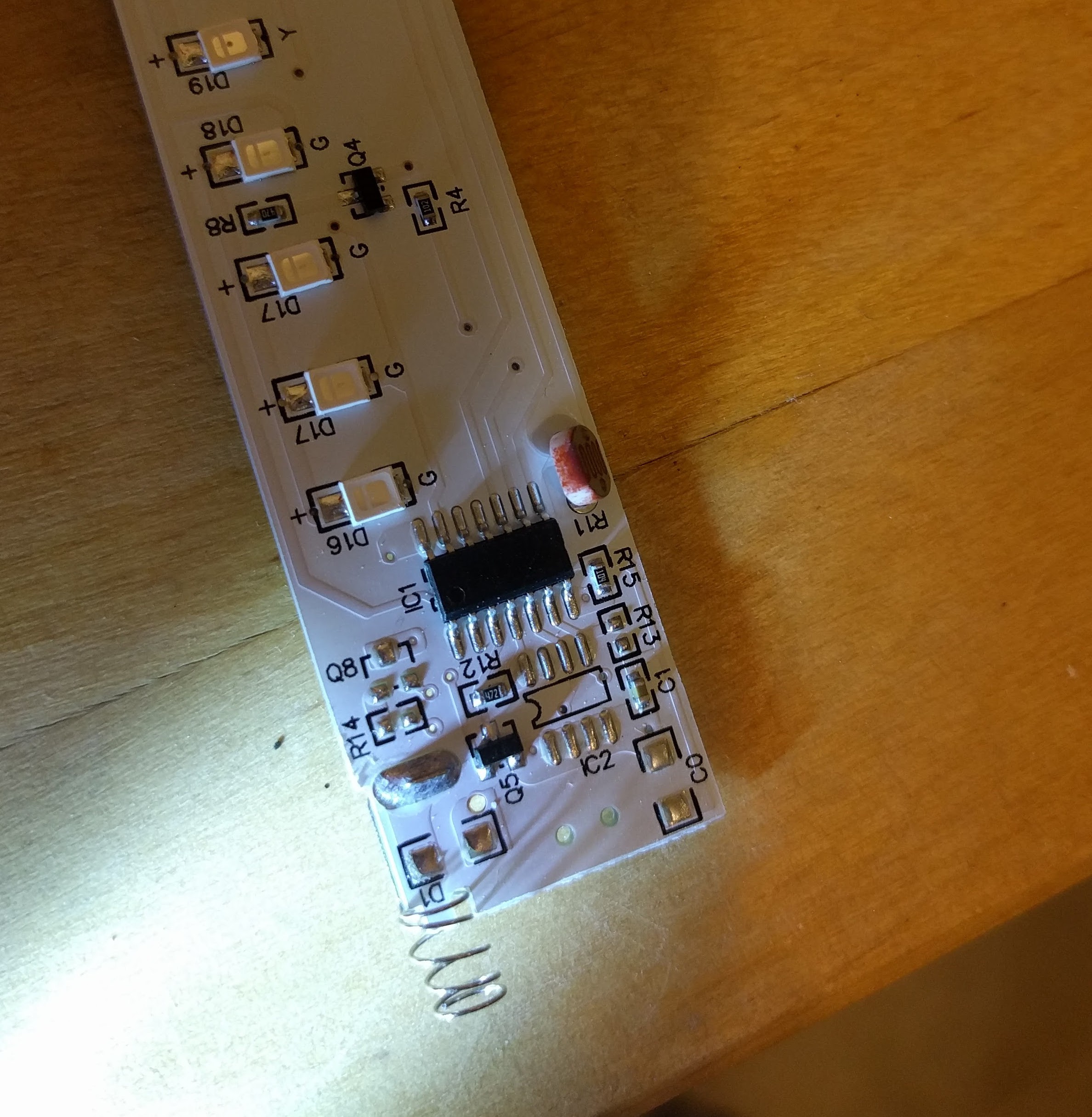
From here, and then with a quick assist from my handy multimeter, I have drawn a schematic!
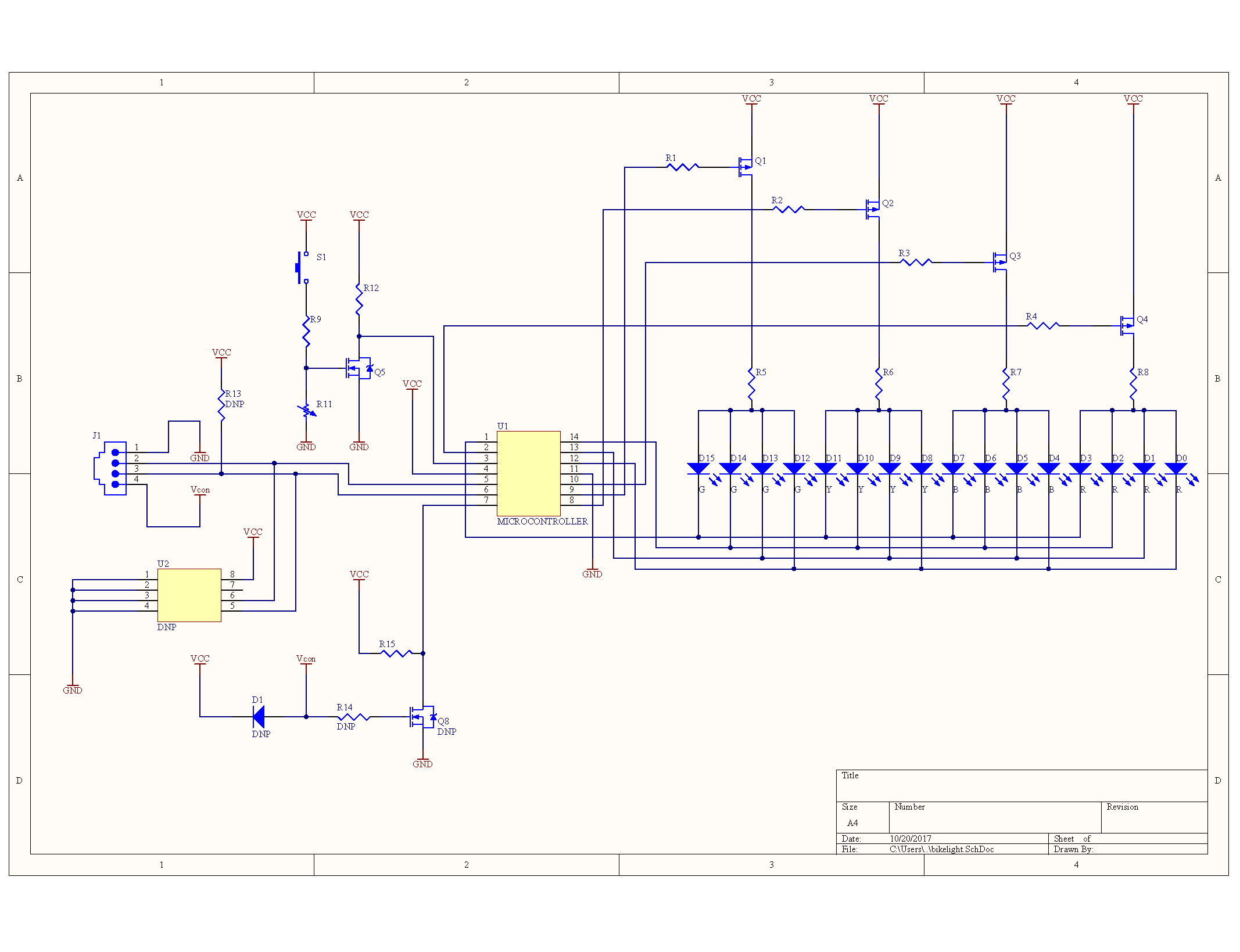
There were a few funny things with this circuit.
The whole bottom-left section, and the connector are unpopulated - Cost reductions on display. U2 is likely an I2C flash chip, all connected to a 4-pin connector and some power switchover circuitry. AT24C02 fits the pinout of the chip, but any flash chip is identical, pretty much.
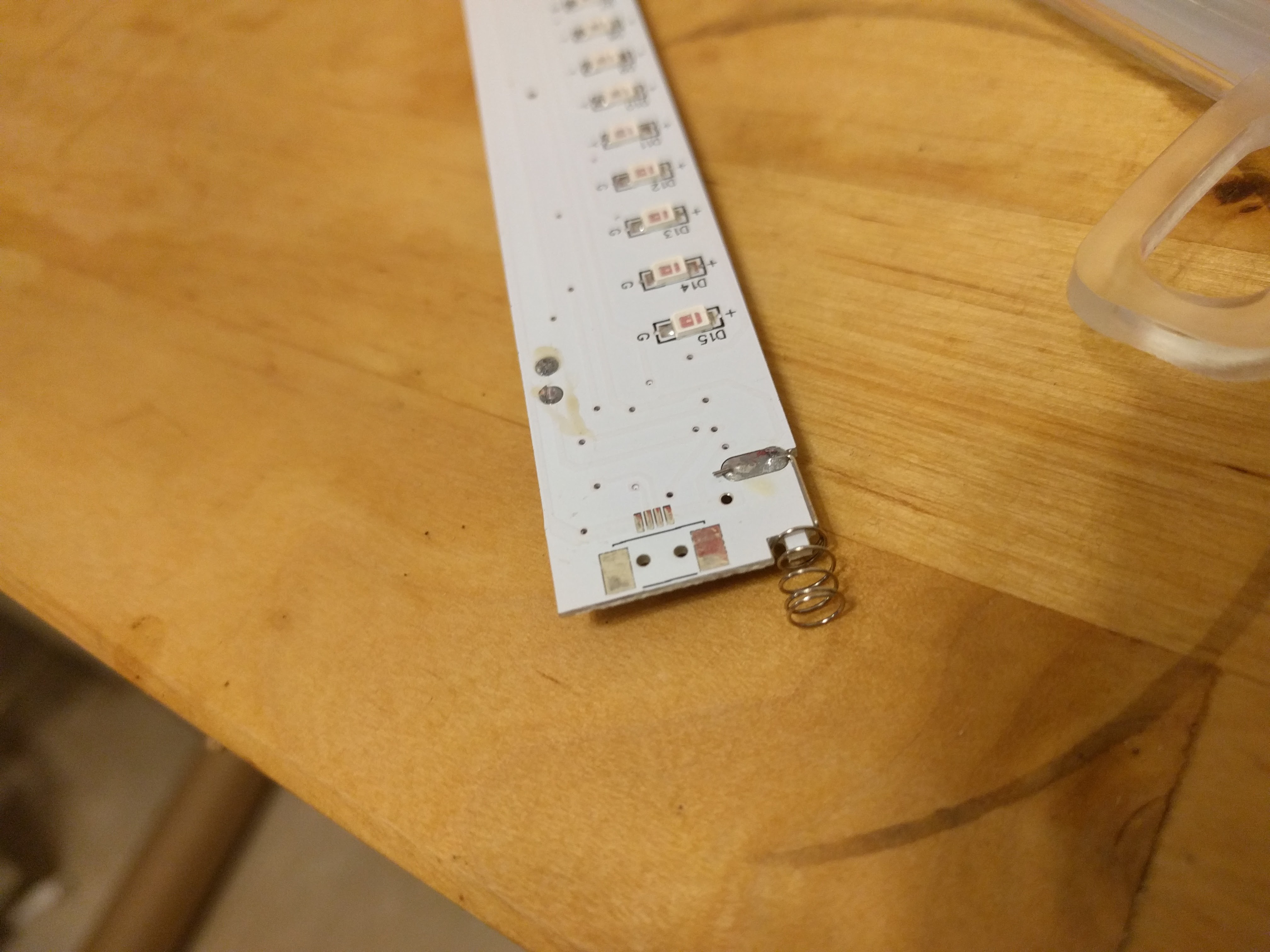
Not shown are the duplicate LEDs. Matching LEDs on each side are in parallel. On one side, they count from 0-15, and then on the other from 16-30 (there are two D17s, and no D31).
The LED is array is set up in an interesting configuration where each high-side control can select a bank of four LEDs, while the low-side controls which LED in the bank is on.
R11 is a light-dependent resistor, and along with S1 (the vibration switch), this the microcontroller is woken up only when it is dark out, and the device is moving.
Concentrating on the microcontroller, the unusual power and ground pin locations ruled out all of the listings on Digikey.
The first one I found that fits the bill is the EM78P153B. It's manufactured by Elan Microelectronics Corp, and looks like it's seldom seen outside China. Interesting. Most of their consumer line is one-time-programmable or masked memory, so it's unlikely I'll be able to rewrite it.
Side note: someone should start a database of microcontrollers and where special function pins are, to make identification of unmarked ICs easier.
Discussions
Become a Hackaday.io Member
Create an account to leave a comment. Already have an account? Log In.
That side note is something I miss, too!
Are you sure? yes | no